
ARCHITECTUAL DESIGN POSITION:
Optimising light in a north facing fragment.
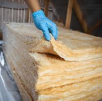
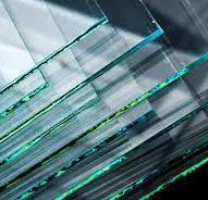
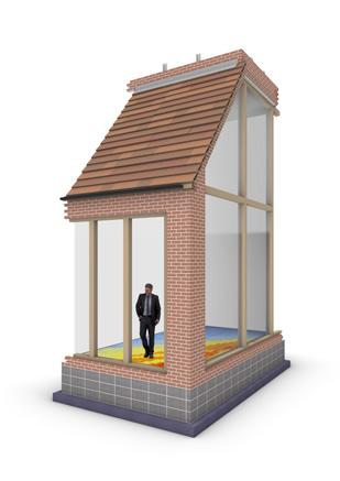
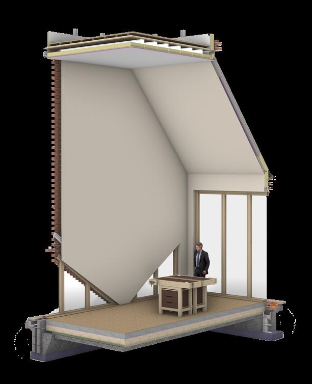
Adhering to the cradle-to-cradle principles, my intervention program involves transforming construction waste into sculptural and artistic materials, thereby offering a new lease of life to discarded resources. My design ambition is to optimize the sunlight in the studio of my fragment whilst considering the utilization of recycled materials as a building material. The aim is to curate a space that not only champions aesthetic appeal but also prioritizes comfort for the artists and sculptors who inhabit it. It's imperative to note that the curtain wall selection is deliberate, aiming to offer passersby a glimpse into the building while also flooding the space with natural light for its inhabitants.
TECHNOLOGIES RESPONSE:
CLIMATE PERFORMANCE

BUILIDNG & LIFE SAFETY
FRAGMENT:
OBJECTIVES:
Using the specified fragment I intend to research the following
- Define the technologies response &Technologies artifacts
- Discover the optimal lighting for the interior (studio & art space)
- Consider the constructability of the brick build-up
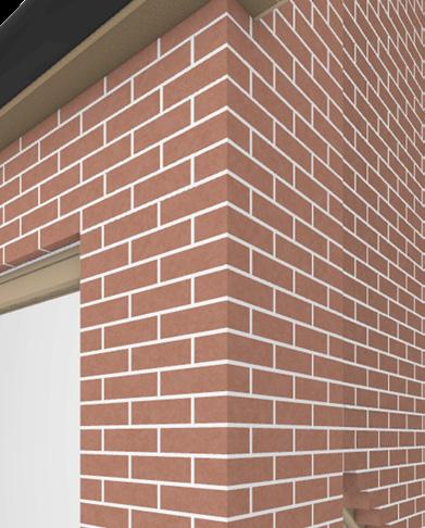
- Consider the brick bond and its opportunities and threats
- Produce a detailed model of my fragment with optimal lighting

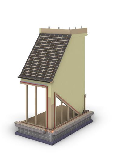
CONSTRUCTABILITY

to construct. CONSTRUCTION SEQUENCE:
DIMENTIONS:
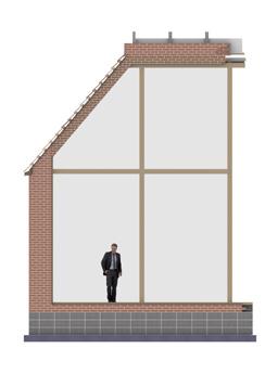
- 3.86m x 6.85m - 26.4m2
- 4.54m x 3.44m - 15.6m2
- 7.13m (enclosed)
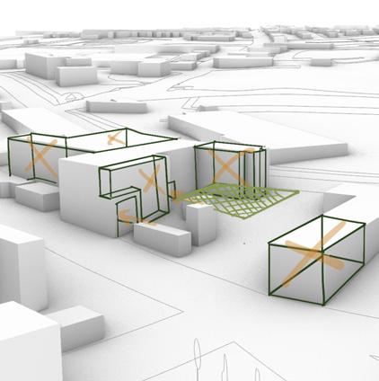
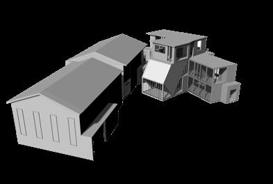
FRAGMENT LOCATION:
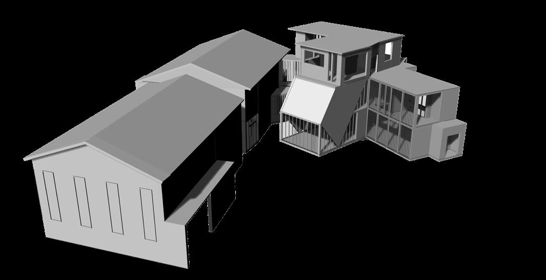
FRAGMENT SELECTION:
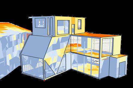
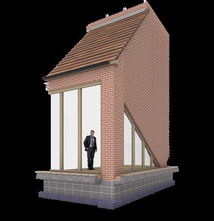
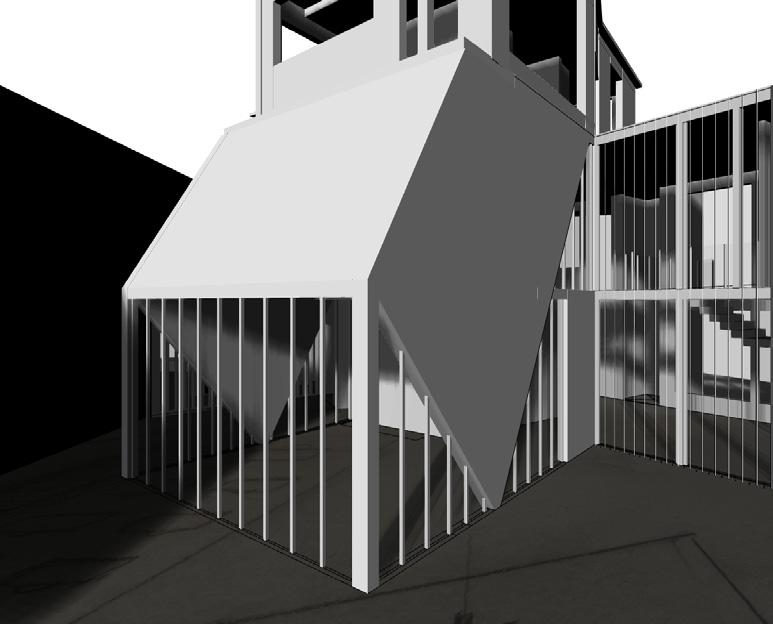
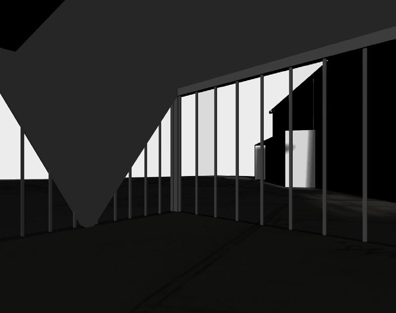
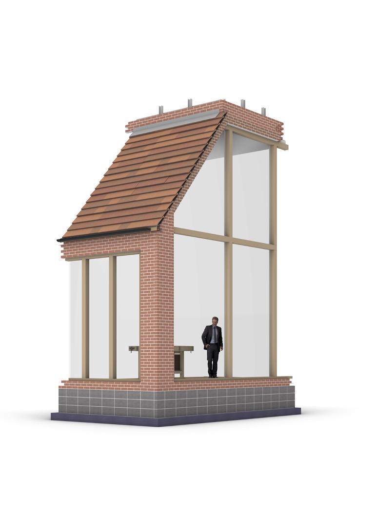
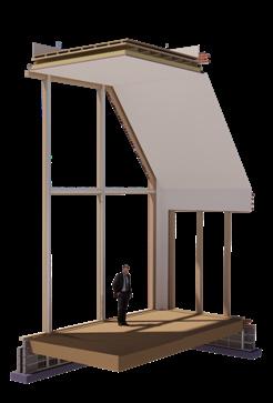
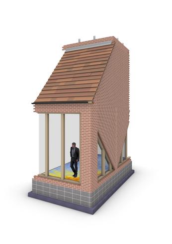
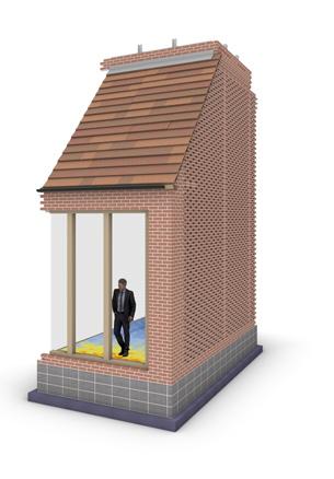
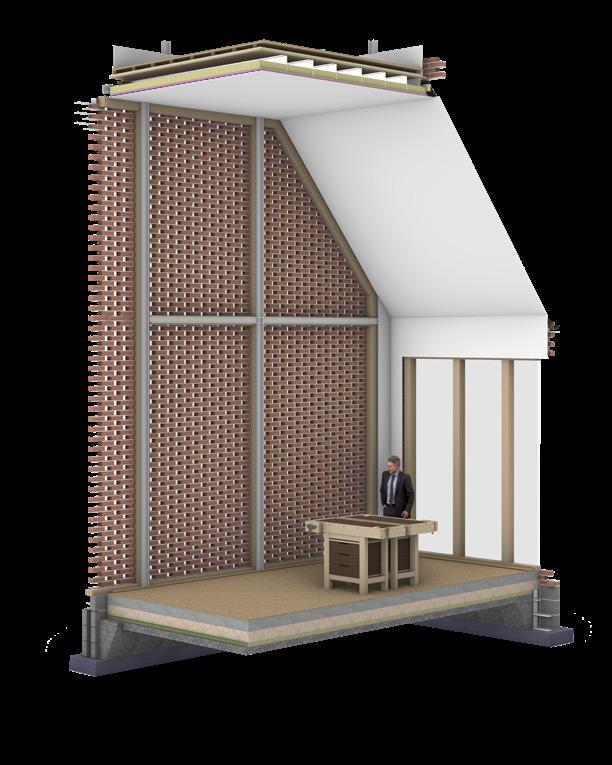
The selected fragment is a point of interest in my intervention as it can be seen from the entrance onto site meaning it must create a point of interest and engagement from far away. To do this have chosen to finish the north wall with a curtain wall of glass to create immediate engagement with the activities inside the building. The west wall receives the most light engagement for this fragment but
TECHNOLOGIES ARTIFACTS:
MATERIALS:
RECLAIMED MATERIAL (where
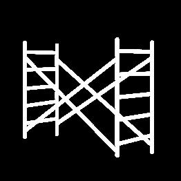
TOOLS:
The construction methods used in this fragment deal with common construction methods on a standard
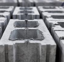
more circular economy. This would be able to teach the early stages of the lifespan of a brick whilst the intervention demonstrates the process after the end of life.


PROCESSES:
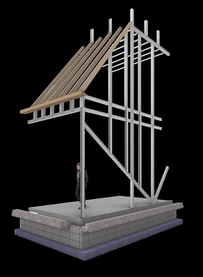
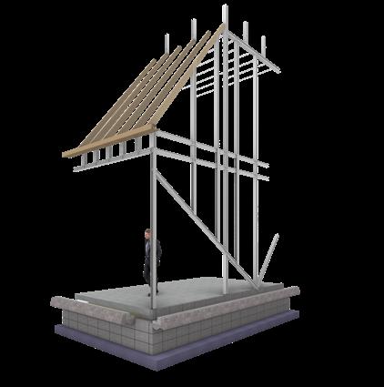
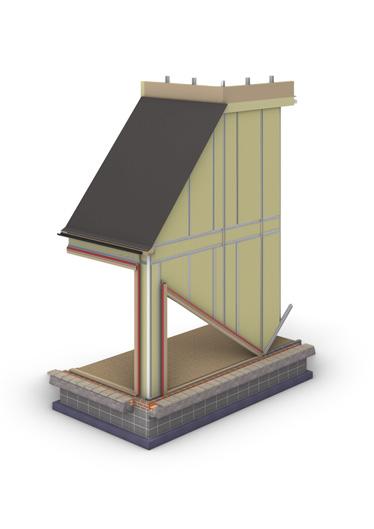
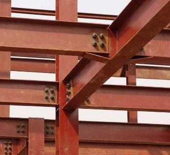
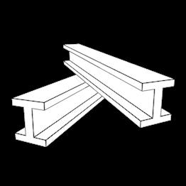
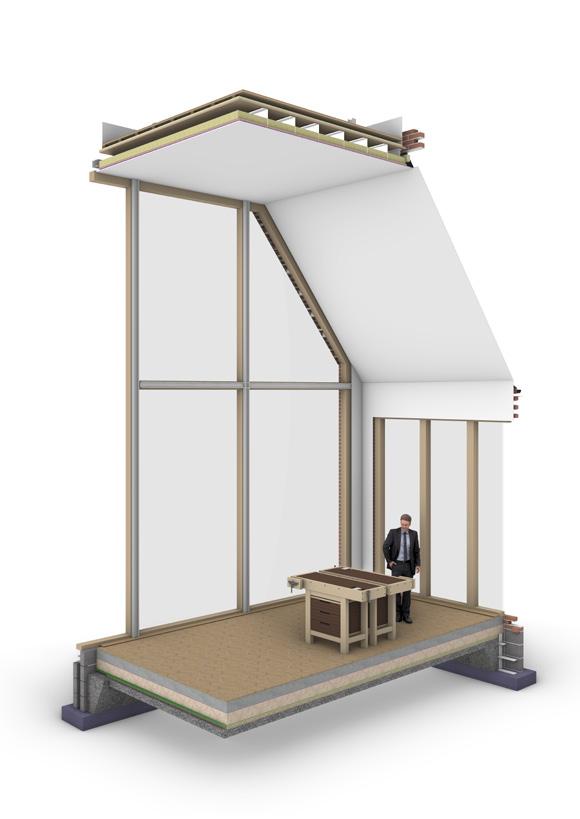
This construction sequence is the most efficient way to assemble this fragment, its standard construction sequence minimizes the need for specialist assembly. Due to the required height of the beams and the specific joints required elsewhere in the building, the frame is steel offering
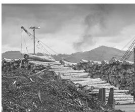


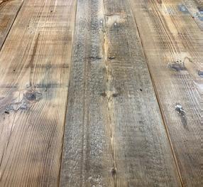
As diagrammed brick and timber, even with standard sizing, may need to be retreated, or cleaned before considered fit for construction. this does increase embodied energy but not significantly enough to justify the use of a virgin material.
PROTOTYPING:
ITTERATIVE TESTING | RECORD OF PROCESS
REASONS FOR PROYTOTYPING:
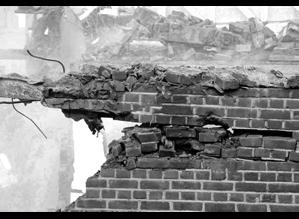
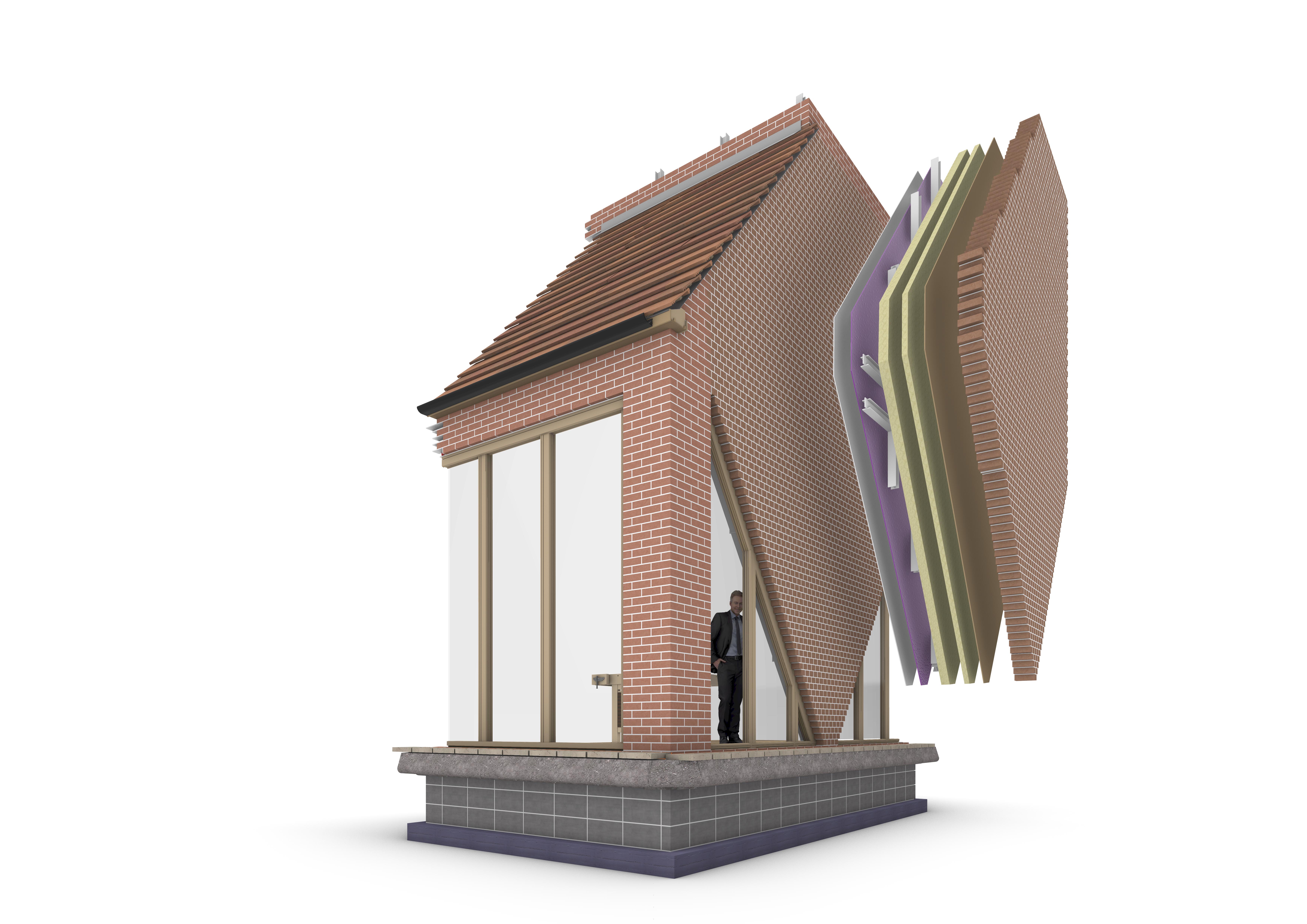
In line with the intervention's focus on repurposing construction waste into artistic elements, achieving solar shading using repurposed brick is essential. This approach not only aligns with the program's ethos but also elevates the building itself into a work of aRt. This fragment serves as a practical demonstration of how brick can be repurposed to provide solar shading, showcasing the innovative potential of sustainable design. If repurposed brick cladding proves effective in optimizing daylight intake within the studio, it can be applied elsewhere in the building.
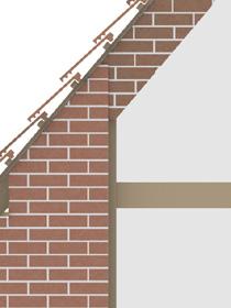
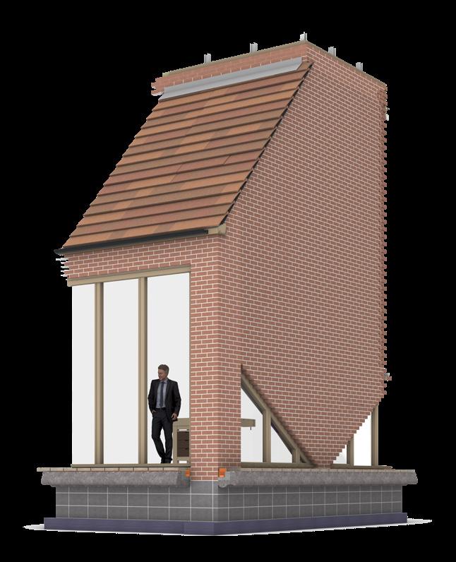
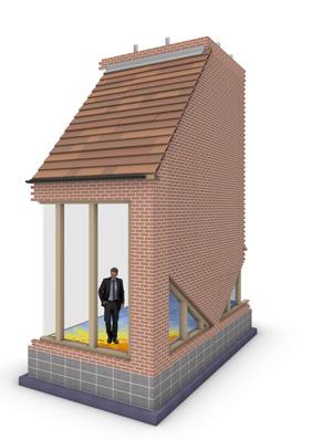
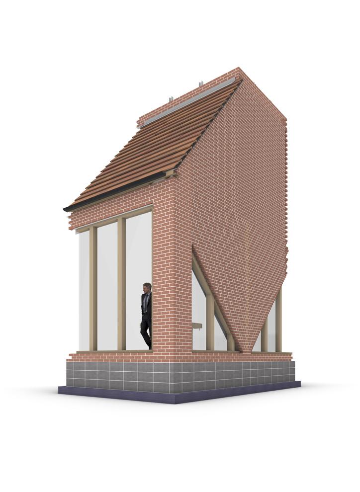
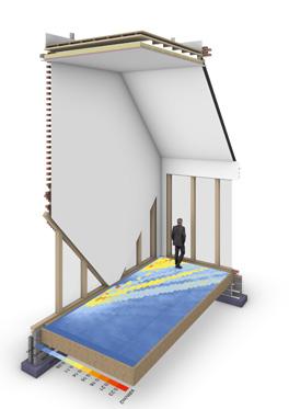
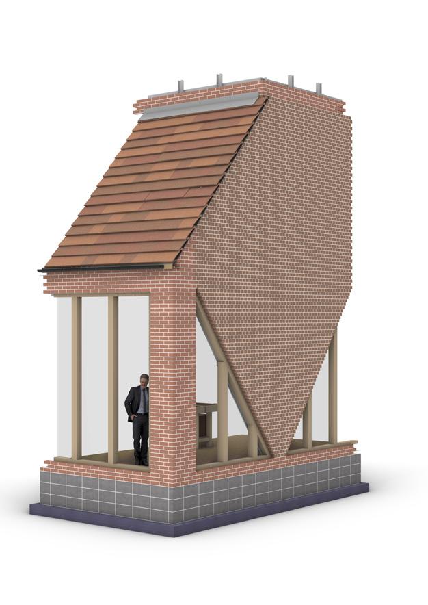
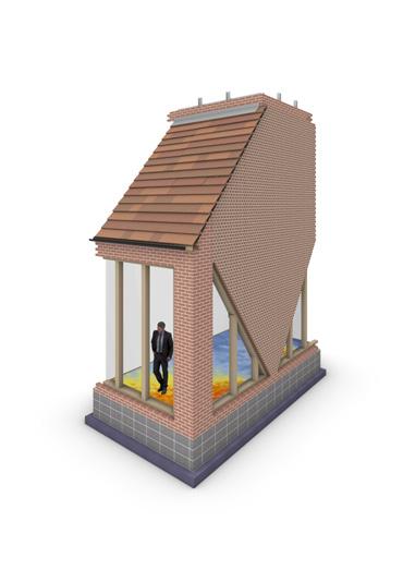
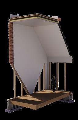
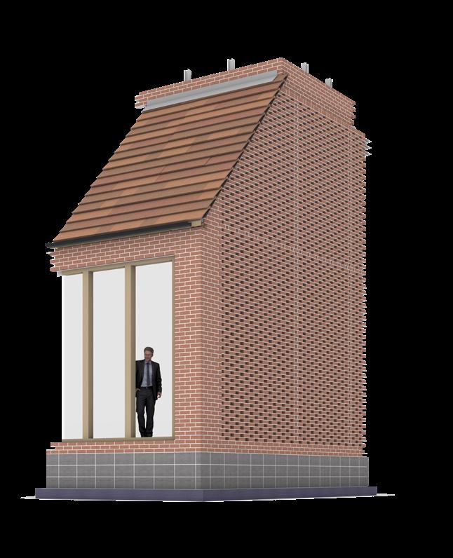
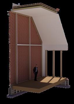
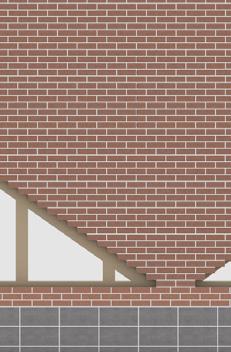
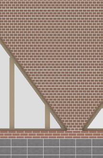
The initial design for this fragment was inspired by the image of a brick positioned on its corner leaning against others, resulting in a triangular-shaped window on the west façade meeting a curtain wall on the north facade. Starting with this design concept as a foundation, it's crucial to explore how iterating the repurposed brick cladding can influence the daylight factor within the studio and workshop space whilst optimizing the use of the repurposed brick for both its form and function.
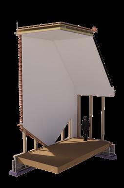
ITERATION 1: Maximum Daylight Factor | Control
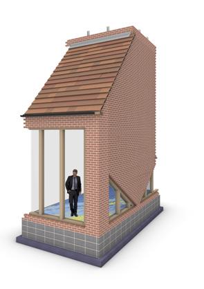
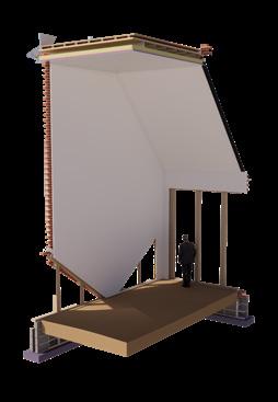
ITERATION 2: Initial deaign approach 33°
ITTERATIVE CRITERIA:
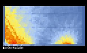
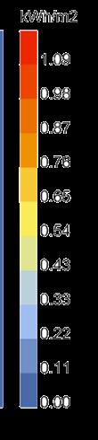
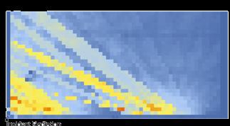
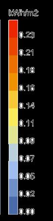
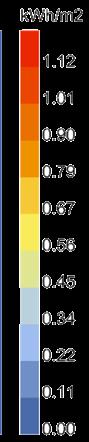
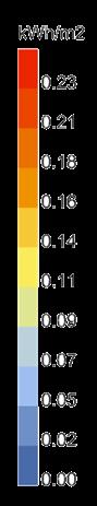
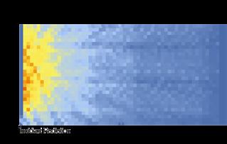
- This test provides quantitative and qualitative data on the radiation factor using the two solstices as comparable.
- The angle must be set from the same base connection, as it aligns with a critical load-bearing steel joint that is located there.
- All iterations must prioritize the use of recycled bricks as the primary material, considering standardized sizes, brick type, brick bond, and freeze/thaw resistance.
- Northan light is considered beneficial for studios achieving diffused light without harsh glare and excessive heat gain (critical to avoid for some paints and materials). This fragment is shaded by the rest of the intervention creating a need for glazing in the west wall bringing natural light in winter months, and trying to avoid overheating and too much direct light.
OBJECTIVE:
Maximize natural lighting in winter (A) and minimize overheating in summer (B) whilst considering materiality, energy performance & aesthetics. Out of the 5 iterations which achieves closest to both A&B?
HYPOTHOSIS:
Iteration 3 will be able to minimize overheating whilst achieving a good amount of natural light in winter but may be impractical to build. Iteration 5 will achieve the best results regarding radiation but doesn't achieve the required aesthetic.
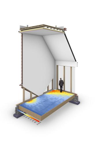
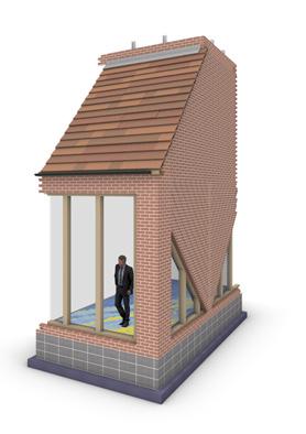
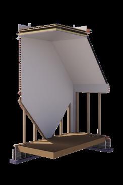
ITERATION 3: Angle increased | 46.38°
Maximizing daylight in the fragment consists of removing the brick cladding and continuing the curtain wall onto the west-facing
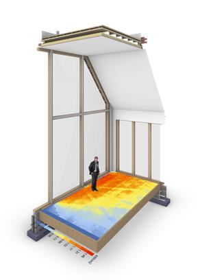
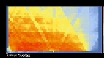
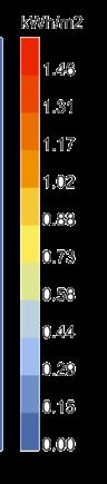
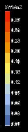
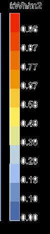
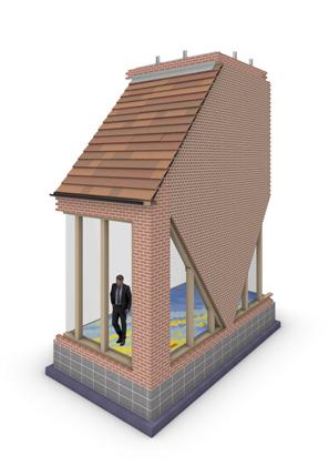
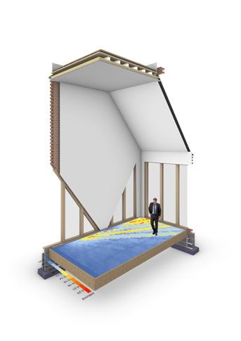
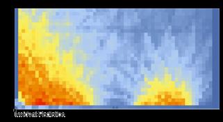
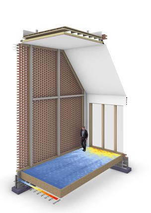
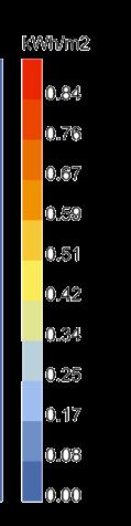
Used as a control, this iteration exposes the west wall which shows the maximum radiant heat distributed in the studio using the two solstices as comparables. This iteration shows high levels of heat gain in both seasons and reaching 1.46KWH/M2 in summer, the fragment would certainly overheat. Moreover, it would achieve too much direct natural light for an optimal studio potentially damaging materials, and would require ventilation strategies to cool the fragment in summer and heat in winter to attempt to
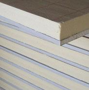
This iteration uses specialized panels of triple-glazed glass achieving a U value of 0.7 W/m2k which shows significantly worse thermal performance than a wall build leading to the need for mechanical heating systems and limiting the possibility of natural ventilation.

This iteration provides a control mechanism to demonstrate the maximum radiation gain possible, facilitating a more thorough analysis of shading devices. It is evident that during summer months, there would be excessive radiation exposure, with a high proportion of the area receiving 1.46 kWh/m². Direct sunlight would also impact the workspace, posing a risk of material and art damage while also hindering consistent lighting.
The wall composition primarily consists of glass, necessitating the production of custom glass panels for the project and extensive machinery for installation. The energy performance of this configuration is too high, mandating mechanical heating to maintain suitable conditions.
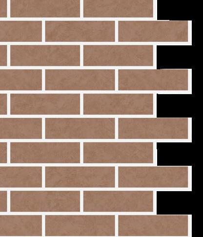
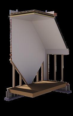
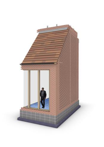
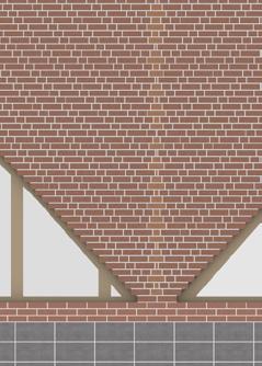
The initial design approach consists of the bricks being clad in a running bond which is considered one of the most simple bonds for construction. This bond creates a diagonal angle of 33.69°.
expected the radiation factor increases in this iteration as the percentage of glazing
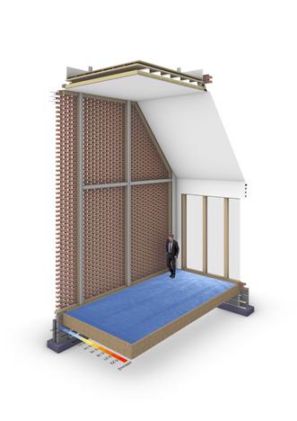
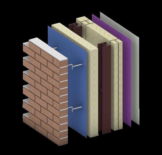
Unlike the control (iteration 1), the west wall build-up has a good thermal performance of 0.16W/m2k which increases energy efficiency in the fragment, in turn, limiting the use of operational energy required.

While the fragment isn't overexposed in summer months, it lacks sufficient light in winter for the artists, rendering this iteration suboptimal. The aesthetic also suffers as although the windows' primary purpose is for lighting in this instance, it doesn't allow an average adult to look through it making it have less purpose for the user.
The angle in question is determined by employing the widely used running bond pattern for bricks. In this particular case, there is an overhang of 107.5 mm from the brick, indicating the need for specialized water-resistant bricks that may alter the overall appearance. Supporting this overhang may necessitate consulting a structural engineer to ensure the bricks are securely placed.
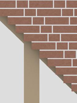

While simulation results favour this iteration due to optimal natural light in winter and controlled radiation in summer, its unique brick bond presents practical challenges for affordability and feasibility. It would require reinforcement in a lot of areas which doesn't achieve a material-first process as it is introducing new material where it may not be necessary.
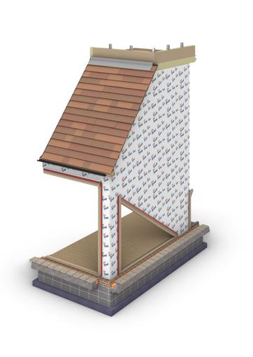
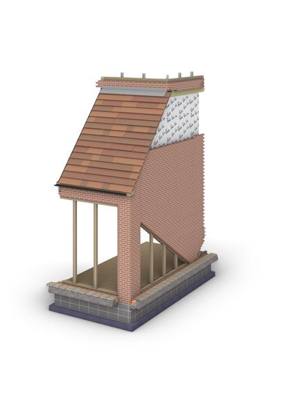
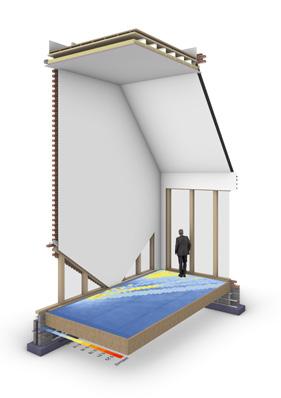
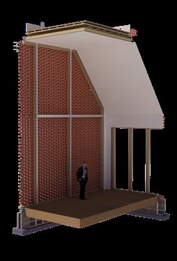
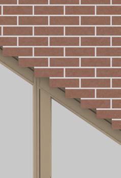
Only 71mm of brick would be exposed due to the overhang, a significant reduction compared to Iteration 2. This wall build-up ensures good thermal performance while closely aligning with the aesthetics of my initial design fragment (refer to page 1).
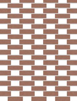
MATERIALITY & BOND: MATERIALITY & BOND:
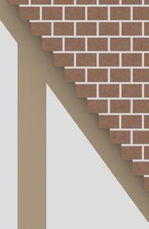
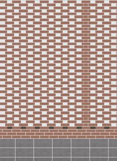

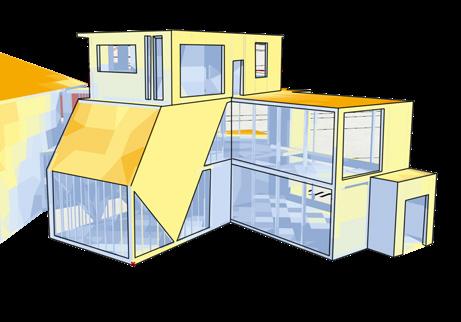
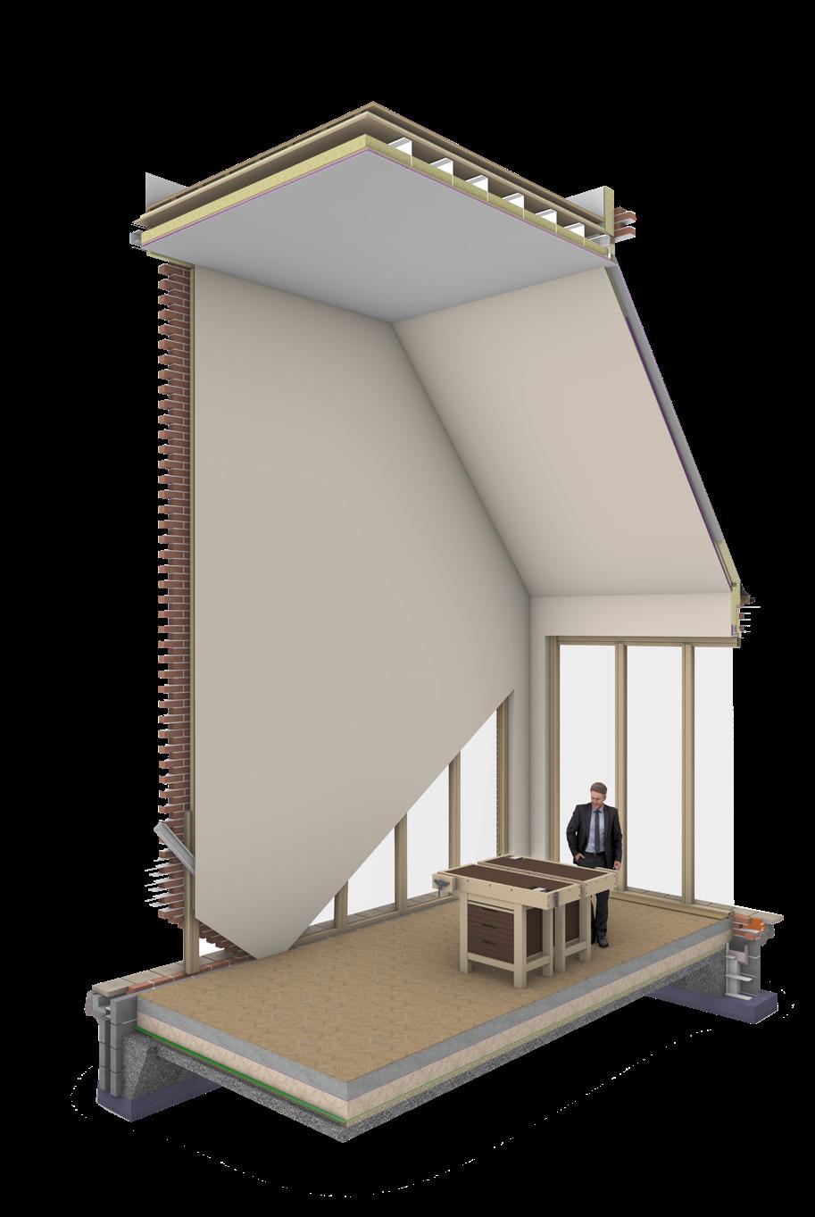
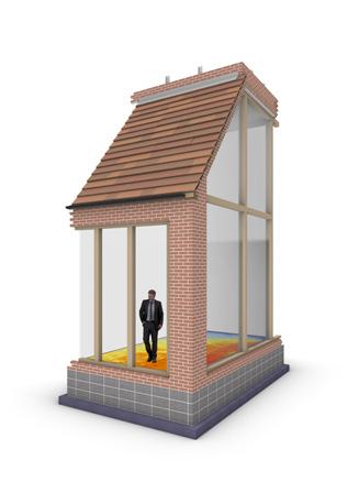
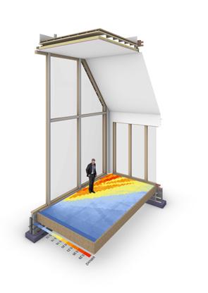
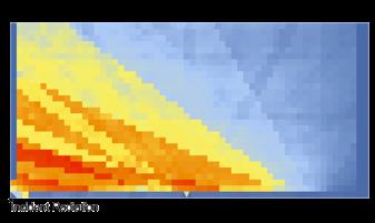
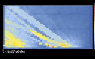
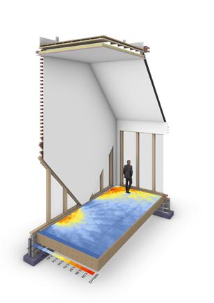
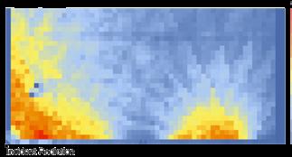
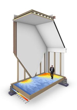
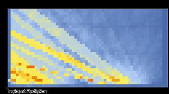
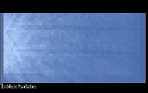
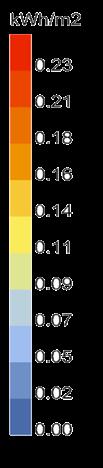
This iteration is highlighted in orange as it is optimal for my goals of maximizing natural light in winter and minimizing radiation in summer months. While summer radiation levels are high, the red and orange areas facilitate circulation around main working areas with low radiation levels. As a result, there is limited direct light on art and sculpture but optimized reflected light throughout the room. Additionally, an interior shading device can effectively mitigate overheating in summer.
The wall build-up with reclaimed brick not only gives the bricks a new life but also reduces embodied carbon. This approach achieves excellent thermal performance, reducing the need for excessive mechanical heating during winter months.
to specified high water-resistant brick due to the reclaimed brick's faster weathering.
The glass wall's low U-value compromises thermal performance, necessitating mechanical heating and resulting in increased carbon emissions from operational energy use.
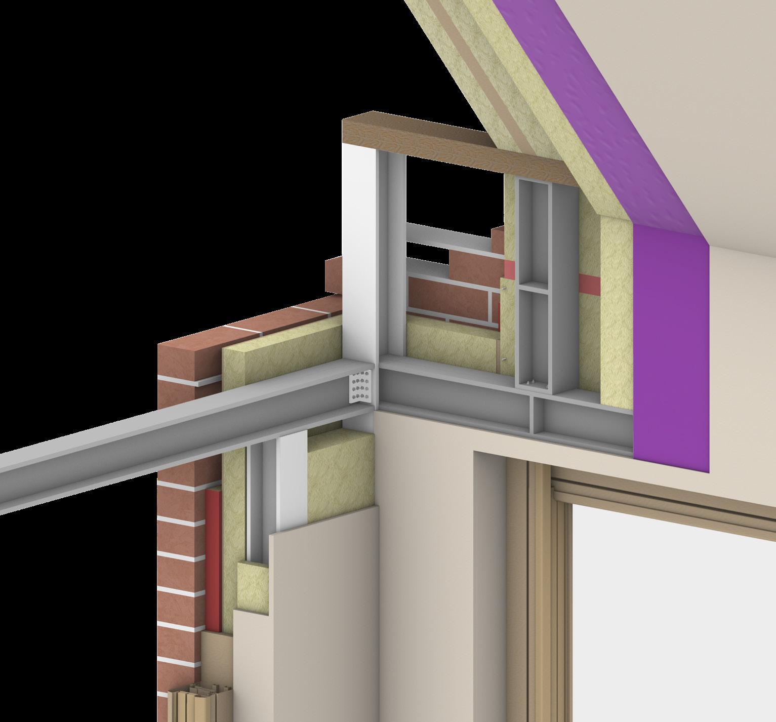
TECHNICAL DETAIL:
REFLECTIONS ON INITIAL POSITION & DESIGN INSIGHTS
CLIMATE:
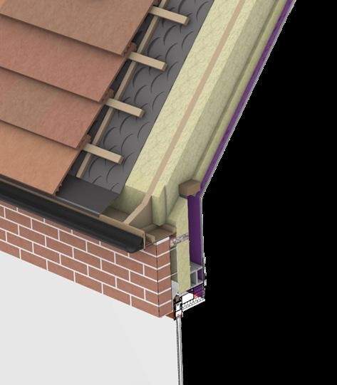
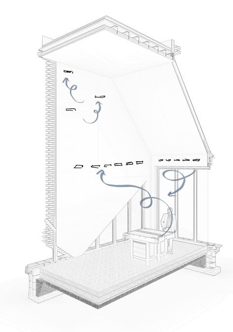
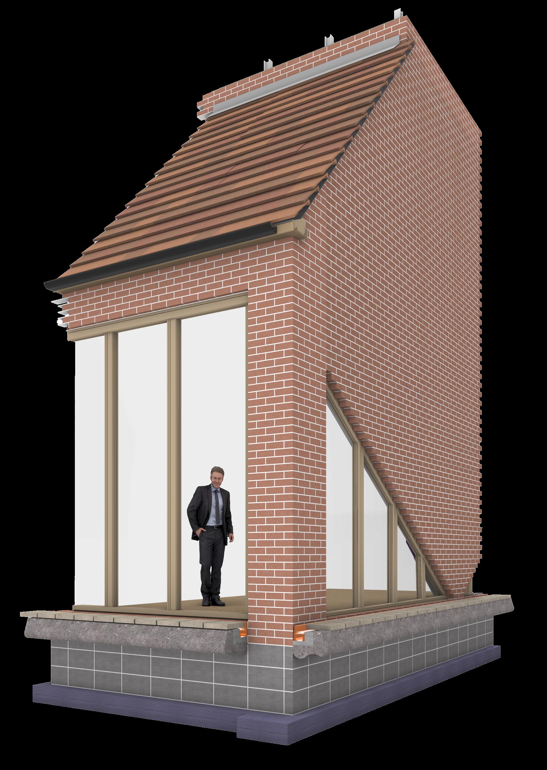
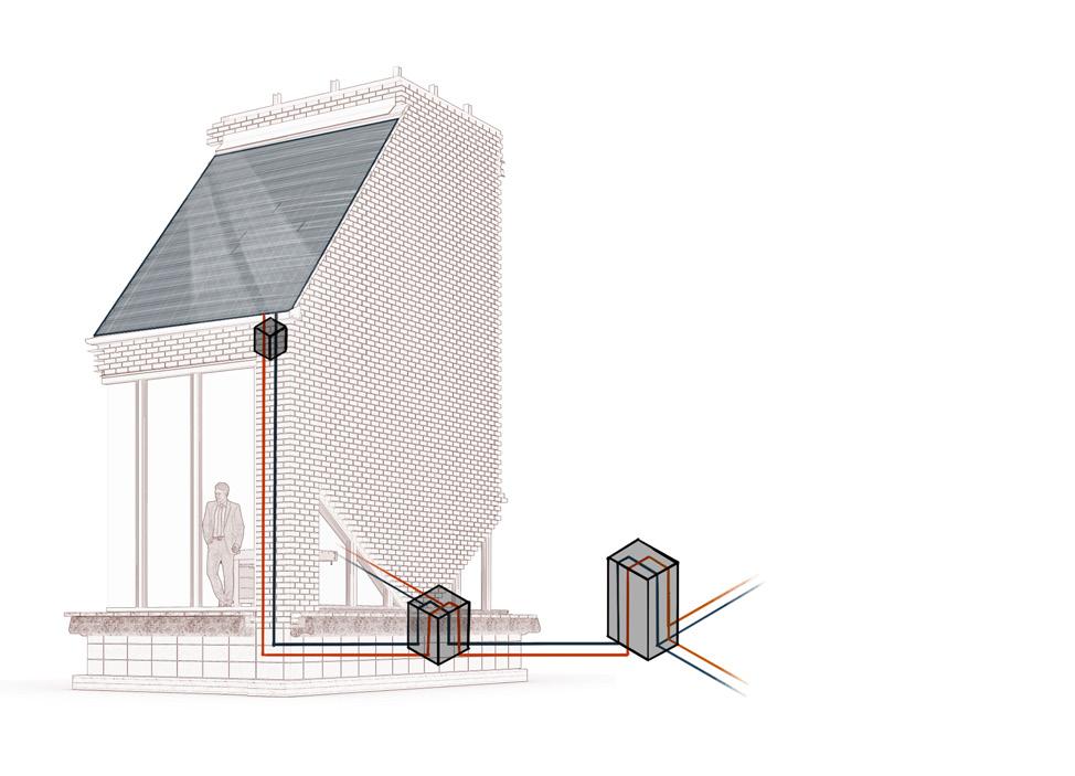
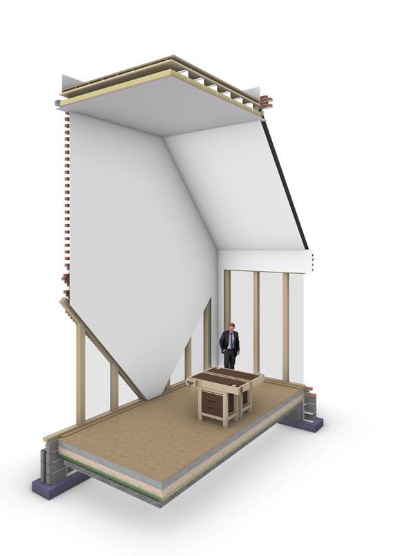
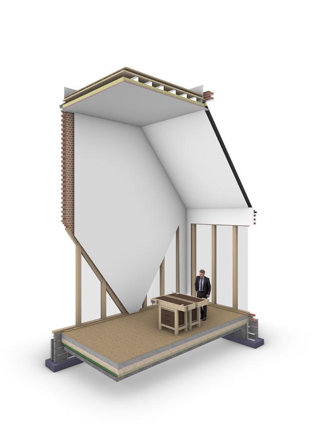
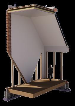
Iterative testing using solar radiance analysis has determined that iteration 4 represents the optimal solar shading device. This iteration maximizes natural light penetration during winter while effectively reducing overheating and excessive direct sunlight exposure during summer months. The design achieved in iteration 4 facilitates a wall build-up that attains an impressive U-value of 0.15 W/m²K, showcasing superior thermal performance. The steep roof design and guttering systems are strategically engineered to ensure efficient water drainage, thereby maintaining structural integrity over time. Additionally, where feasible, brick vents positioned on the west-facing wall capitalize on prevailing southwest winds to facilitate natural ventilation, contributing to a comfortable indoor environment while promoting sustainable building practices.
BUILDING AND LIFE SAFETY:
In this iteration, the main load-bearing steel frame is concealed behind the angled brick facade, creating a seamless and aesthetic appearance. The steel frame is carefully designed to match the angles of the brickwork, ensuring a cohesive and structurally sound integration. A metal lintel would attach to this frame, providing additional support for the weight of the angled brick and ensuring structural stability over time.
Given that some of the brickwork is exposed to the elements, it's crucial to use high-quality, water-resistant bricks in these areas. This choice helps prevent weathering, water damage, and potential structural issues, ensuring the longevity and durability of the building facade.
CONSTRUCTABILITY:
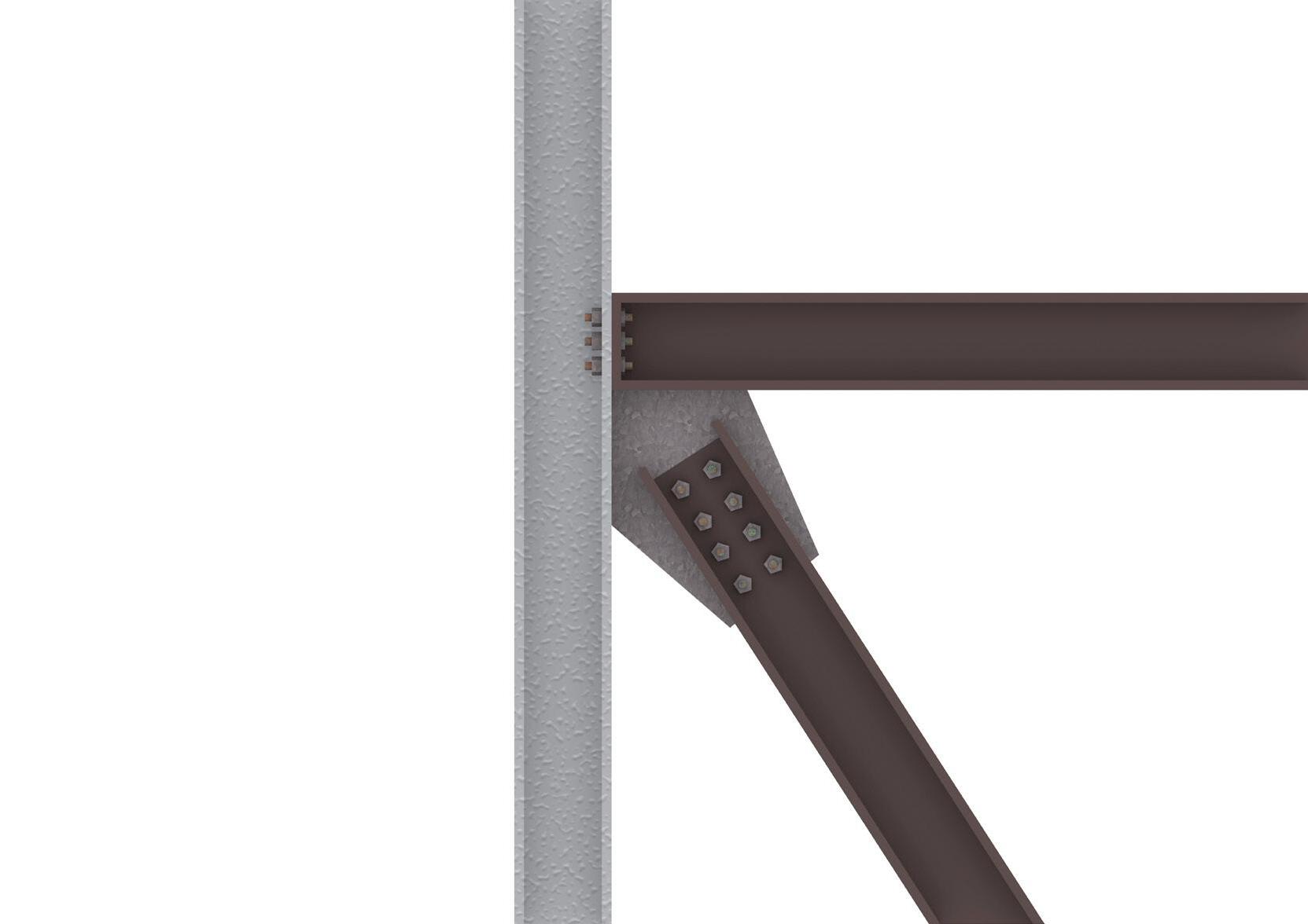
EXAMPLE JOINT SYSTEM
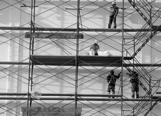
The construction process hasn't changed drastically from the initial fragment, aside from the brick bond, which is still relatively simple to construct and doesn't require specialized contractors. As mentioned, bricklaying could be used as a course to educate and pass on trades, using the construction as an element of the commons. This approach not only promotes skill development within the community but also fosters a sense of ownership and pride in the built environment. It aligns with sustainable practices by empowering local resources and knowledge while creating spaces that serve both functional and educational purposes.
MATERIALITY:
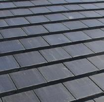
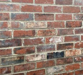
The materiality hasn't changed significantly either; the bricks are repurposed from demolition sites, giving them a new lease of life and limiting embodied carbon in the building. Reclaimed tiles and wood are also utilized, along with recycled steel frames, to further reduce embodied carbon. This approach not only reduces environmental impact by minimizing new material extraction but also adds a unique character to the building through the use of aged and weathered materials.
REFLECTION & FURTHER DEVELOPMENTS:
Solar analysis on page 2 has provided insights into understanding the best natural lighting strategy. The radiation analysis not only sheds light on visual lighting but also on solar heat gain. Iteration 4 has emerged as the most effective option in optimizing both lighting quality and mitigating solar heat gain, showcasing efficient thermal transfer properties and reduced operational energy usage.
While Iteration 4 excels in optimal lighting conditions, additional consideration could be given to exploring lighting dynamics from above and how they interact with the sloped ceiling to create indirect light. This approach leverages natural light entering from above, which can then be diffused and reflected off the sloped ceiling, creating a softer and more evenly distributed illumination throughout the space. More testing would be needed to understand this in better depth.
This 3D model illustrates the intricate connection details within a steel frame, showcasing a versatile joint system applicable across various structural frameworks, including those external to this specific fragment. Bolting serves as the predominant method for joints where feasible. However, in angled joints necessitating enhanced strength and rigidity, welding techniques are strategically employed to forge seamless and durable connections. This standardized approach not only ensures structural integrity but also contributes to overall project savings and timeliness design.
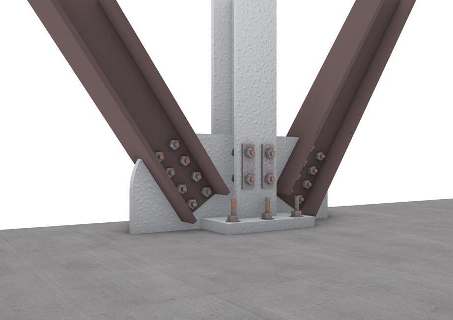
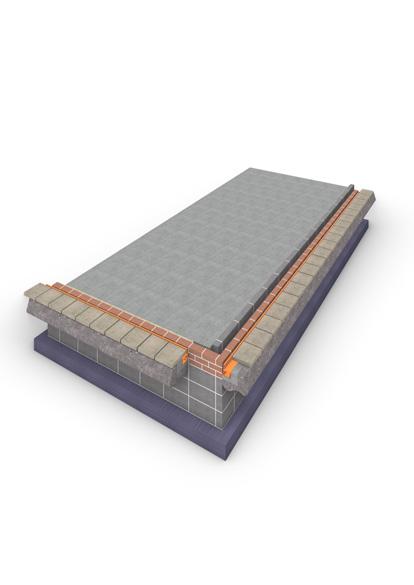
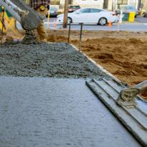
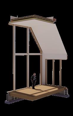
FLOOR / STEEL FRAME JOINT
This 3D model illustrates the crucial role of the central steel bar in bearing the primary structural loads within the building system. The integration of both bolted and welded systems enhances the connection's resilience, ensuring a durable and robust linkage between the steel frame and the concrete slab. The strategic placement and design of these connection elements contribute to the overall structural integrity and load-bearing capacity of the construction, emphasizing the importance of precise engineering in modern building design.