FROM DEBRIS TO DESIGN
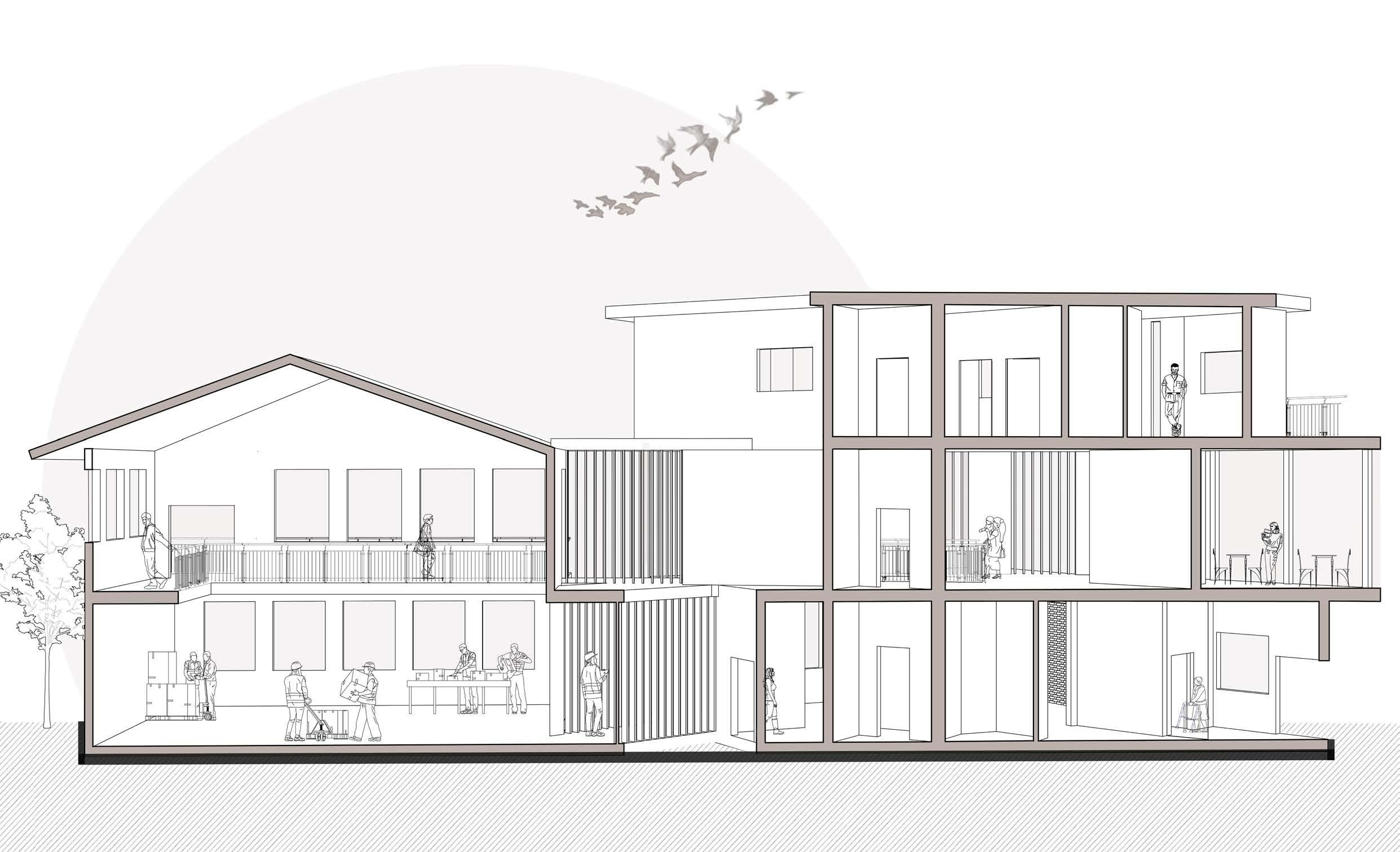
A demonstration of material potential after ‘‘End of Life’’ CONTENTS: Unpacking the breif .....................2 Atilier position.................................4 3.1 Recap..........................................5 Design development...................7 Enviromental analysis.................17 Detailing...........................................18 Programme.....................................20 User analysis..................................21 Masterplan......................................23 Genral arangement plans.........24 External views...............................27 Response to regulations...........28 Structure.........................................29 Construction sequence............30 Reflections.....................................31 Bibliography..................................32 LUCY LEES 21439197
&RCHITCECTURE
Mapping document
I have used this mapping document to outline the contents of the 3.2 submission comprehensively and clearly.
This table can be used as a reference to determine which page corresponds to specific outputs, common principles, and stages in the RIBA Plan of Works.
RIBA SUSTANABLE OUTCOMES:
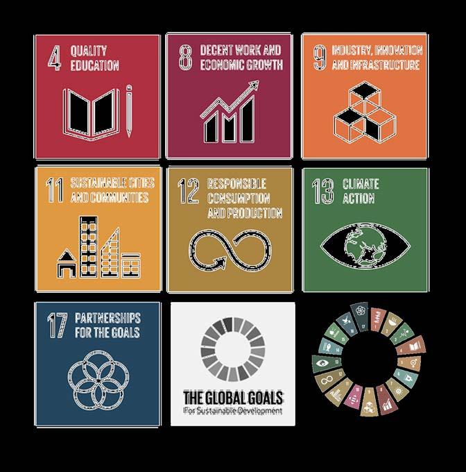
My intervention aligns with the following seven RIBA sustainable goals:
Quality education, economic growth, innovation & infrastructure, sustainable cities and communities, responsible consumption & production, climate action and partnership & goals
While these goals are not explicitly detailed in the mapping document, they have been central to this design project.
DESIGN ANALYSIS
DESIGN DEVELOPMENT
• A clearly developed construction sequence
• A structural proposal and material selection.
• A detailed section
• An experiential detail
• A recap on 3. 1
• A reflective and critical approach to design
• An understanding of the ateliers position.
• D emonstrate user engagement
• A final master-plan
• A complete set of GAs
• A consideration of user experience
• Response to building regulations
• Response to climate emergency
DESIGN RESOLUTION
DESIGN COMMUNICATION & REFLECTION
• The demonstration of your studio scheme through exhibition quality outputs throughout the portfolio
• Craft a convincing argument that narrates the development of your work
• Continuous reflection analysing how you have synthesised and applied the atelier position, technologies and humanities learning into your building design
2
OUTPUTS & CPs RIBA (p.o.w) PAGE no.
30 29 19 18 5/6 all pages 4 12/21/22
all pages all pages all pages CP4 CP5 CP1 CP2 all CPs all CPS CP5 CP2 CP3 CP3 CP2 CP5 CP5 all CPs all CPs all CPs 6 6 5 7 1 - 4 5 N/A 7 1 5 7 - 8 5 6 7 - 8 7 - 8 8
23 24/25/26 12/21/22 8/28 15/16/17
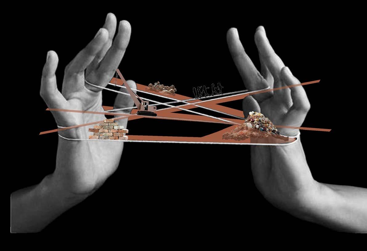
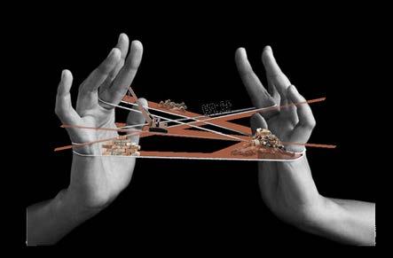
While the typical 'cradle to cradle' imagery suggests a continuous cycle, I prefer using a 'cat's cradle' analogy to describe built environments. It embodies a continuous cycle where different materials are best suited to "restart" their life-cycle at various points. AN
&RCHITCECTURE
Brief & Cradle to cradle
Develop and resolve 3.1 (Design a creative commons):
Begin with the 3.1 Outputs as a foundation, prioritize the atelier aim of "MATERIAL FIRST, DESIGN SECOND" to craft a grounded design showcasing a deep understanding of Sheffield including its stakeholders, community economics, and existing tensions. Thoughtfully select materials, challenging traditional architectural aesthetics to foster a 'common aesthetic.' Address the climate emergency by acknowledging the challenges and limitations of utilizing waste materials.
To create a Creative Commons space, integrate common principles with the RIBA plan of work, strategically prioritizing between them as needed. A successful intervention will result in an efficient Creative Commons that not only serves its purpose but also contributes positively to the community and the environment.

6. PUTTING ECO-EFFECTIVENESS INTO PRACTICE
- Implementing all the previous chapters.
- Critically examine material labelling and gain a depth of knowledge of how it may be ‘better’.
- Intention/ restore / innovate / prepare / intergenerational responsibility
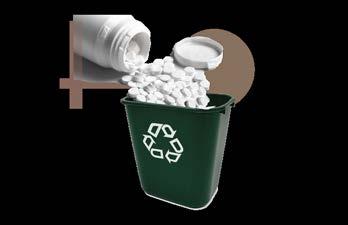
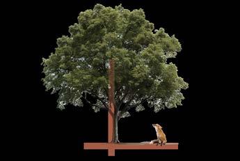
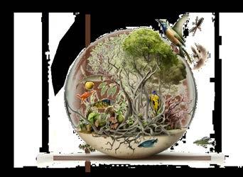
MY INTERPRETATION OF THE 6 CHAPTERS OF: CRADLE TO CRADLE REMAKING THE WAY WE MAKE THINGS
3
Braungart, Michael, 1958-; McDonough, William. (2009)
1. A QUESTION OF DESIGN 2. ‘‘‘LESS BAD’’ IS NO GOOD
3.
ECO-EFFECTIVENESS
4. WASTE = FOOD
ARCHITECTS CRADLE
5. RESPECT DIVERSITY
&RCHITCECTURE
Plan of works x Common Principles
STRIP: GENERATIVE POSSIBILITIES OF ARCHITECTURAL TERMS
5 points in my concept which need further exploration
REVIEW THE COMMON PRINCIPLES:
Reflecting on 3.1 output
CP1: Creative Cultures: use ethical practices & welcome differences.
-The intervention includes ethical practices for workers and users
- Consider ethical practice of construction and processes in 3.2
CP2: Creative Users: include different actors and communities
- The intervention is open to all people but does provide a platform for young artists
- Consider technologies adapted for wheelchair users.
CP3: Creative Places: protect and produce a commons
- The intervention acts as a commons from the point of construction onwards
CP4: Creative Programmes: promote cultural, social, political & economic conditions.
- The intervention helps young professionals start their career
- The residential area needs updating for this to work effectively.
CP5: Creative Resources: use social & ecologically just methods, materials & labour.
- My intervention uses locally sourced and, where possible, recycled materials. Local contractors make certain the intervention feeds back into the economy.
8 - CERTIFYING PRACTICAL COMPLETION:
To be defined
Monitoring building use and carbon emissions to be able to define areas of improvement that can be implemented in building maintenance and/or used as insight for future interventions.
7 - CERTIFYING PRACTICAL COMPLETION:
To be defined
Handing over to the user explaining how to effectively utilize the space and maintain carbon offsets, including the handover of deconstruction and ruse methodology.
RIBA Plan of Works 1 - 4
The outputs of 3.1 included a thorough user and site analysis, a comprehensive project brief and concept, and a meticulously coordinated spatial design. These aspects encompassed the initial four steps outlined in the RIBA plan of work. However, adopting the atelier’s approach of “material first, design second” for the final phases may pose challenges during the development and manufacturing stages. To mitigate potential difficulties, careful consideration and thorough justification of each material choice are imperative.
6 - MANUFACTURING & CONSTRUCTION COMMENCES: To be defined
Using locally sourced materials (such as demolition waste) and involving local people in construction limits transport carbon costs and circulating money within the Sheffield community.
5 - DEVELOPING INFORMATION:
To be defined
Using basic knowledge of the details at this stage, they need to be developed to create defined information for manufacturing and construction using cradle-to-cradle principles to ensure a low-carbon intervention.


3.1:
INTRODUCTION
& OVERVIEW
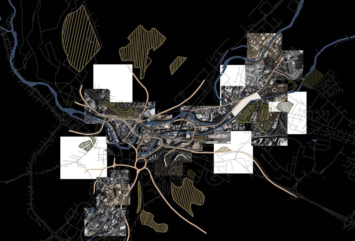
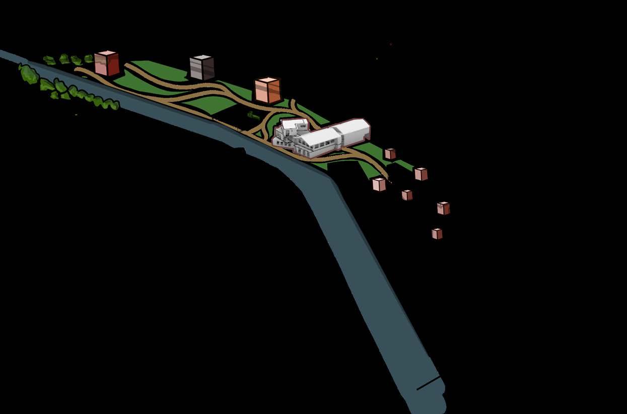
Site context
DESIGN A CREATIVE COMMONS
A commons is a collectively shared resource or asset utilized and managed by a community or society for their mutual benefit.
FINISHING POINTS:
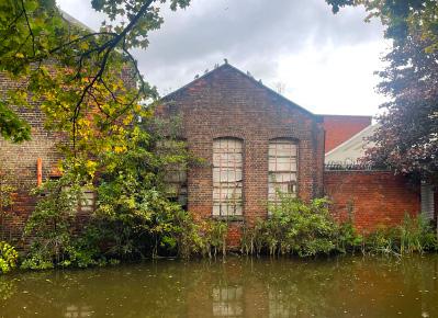
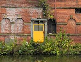
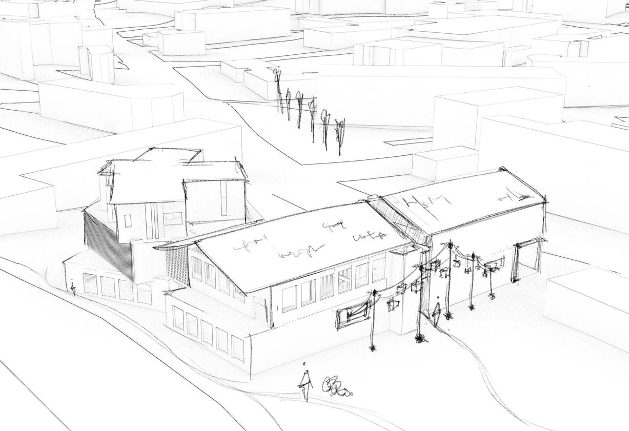
3.1 was concluded with a program consisting of a production line revitalizing waste into art, a viewing walkway, and a residential apartment that sleeps up to 8 people, housing the workers from the intervention. This intervention is situated adjacent to the Tinsley Canal, Attercliffe, Sheffield.
Upon review elements to resolve further include:
- The need to revisit and rework the residential apartment to create a better user experience.
- Consider the range of users and how to make as many elements accessible as possible (consider material transport)
- Aligning with the atelier’s principles of ‘material first’ consider technologies that will mediate embodied and operational carbon.
- Rework GAs to adhere to regulations
- Add materiality to elevations
- Develop and resolve building structure and construction sequence.
WHY SPARTON WORKS:
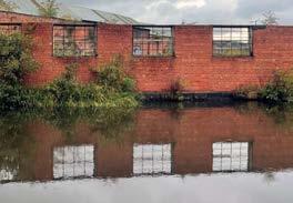
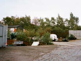
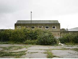
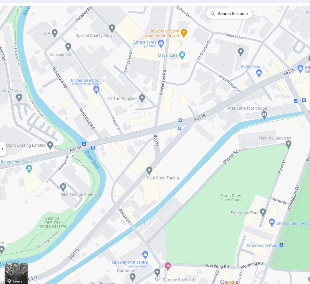
The site, situated adjacent to the Tinsley canal and a main road leading to Sheffield City centre, is currently underutilized, presenting a prime opportunity for establishing a hub focused on imparting skills and knowledge. This hub will not only promote personal growth for individuals but also contribute significantly to the advancement of the community as a whole.

5
3.1: PROGRAMME
User & Usage
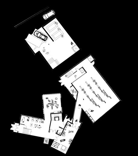
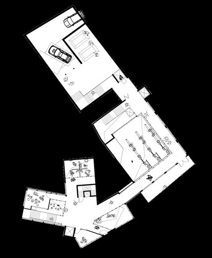
Considering the outputs from 3.1 to determine the next steps in development.
The two most notable initiatives in my 3.1 intervention are 1. Distinction between space and use, separating the floors into a discussion of private/ public/private users. 2. The material choice determined by the P.P.S.
Continuing into 3.2 it is essential to promote and expand on both these initiatives to solidify the program and Material first approach.
RESPONSE TO CPS:
The proposed design intervention of 3.1 deals with all 5 common principles but there is cause for further development in each of them.
Using the material selection and programme layout as a basis I intent to develop the intervention further to meet all the CPs at a better standard.
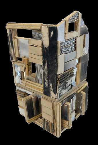
Using a prototype performance space to determine the material pallet & initial program of my intervention. This model demonstrates the intent to promote the use of recycled cladding in the intervention with an emphasis on using recycled material from in and around the site to limit embodied carbon and transport carbon costs.
Material Pallet:
- Corrugated steel
- Reclaimed timber cladding
- Reclaimed brick
Structural initiatives:
- Re purposing existing buildings (limit carbon cost)
- Timber / Steel frame structure
6
WORKER: RESIDENTIAL: PUBLIC USER:
Material drop off Store Organise Transport CRUSHING MATERIAL Public entrance Offices & Ancillary Viewing walkway Workshop Organise Organise Store Store Ancillary Art Class Art Studio Store Crush Brick Sculpture Assembly Viewing Platform Communal kitchen Balcony Bedroom Bedroom Bedroom Bedroom WORKER: PUBLIC USER: RESIDENTIAL: Spacial adjacency diagram: Material selection (P.P.S.)
:
CP4 CP1 CP5 CP3 CP2
STAGE 4
CONCEPT REWORK
The S.T.R.I.P.
STRIP: GENERATIVE POSSIBILITIES OF ARCHITECTURAL TERMS
5 points in my concept which need further exploration
SCALE
Manipulating the scale and reconfiguring my plans from 3.1 to emphasize areas of strength and weakness by becoming unfamiliar with the established plans and looking at them in a new light.
THRESHOLD
Emphasis is placed on the areas of transition from one area to another. There are fundamentally 3 processes within the intervention and the viewer must be able to distinguish these processes through thresholds. Developing lighting and texture strategies to emphasize this.
REVEAL
Similar to ‘threshold’, ‘reveal’ links to how the area is perceived whether it be the transition from one area to another or the way the individual views a space. Further consideration is needed in each space as to how they are revealed in the promenade.
ITERATE
Iterations of the current plan are essential to guarantee the optimal spatial arrangement. Using iteration as a principle, different outcomes are provided which can become comparable to guarantee successful design.
PURPOSE
The purpose of this intervention is to simultaneously educate and take action. To do this there must be an understanding of what is the constant people or material. Material left alone is constant making it imperative to minimize disruption of natural material.
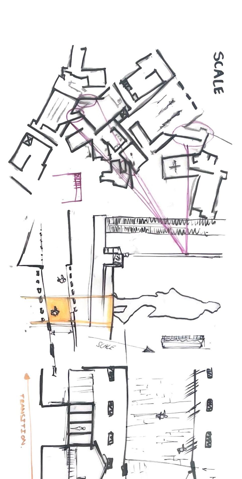
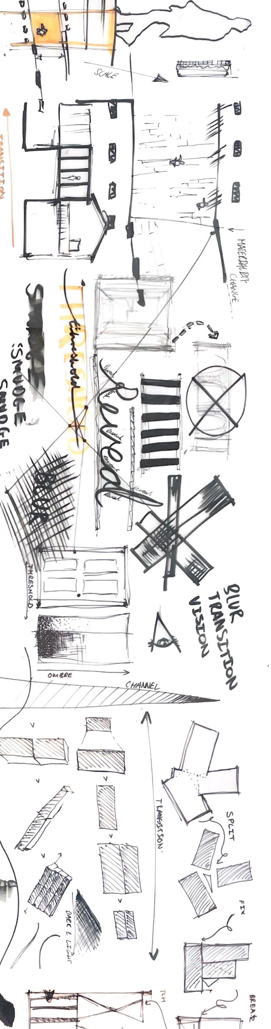
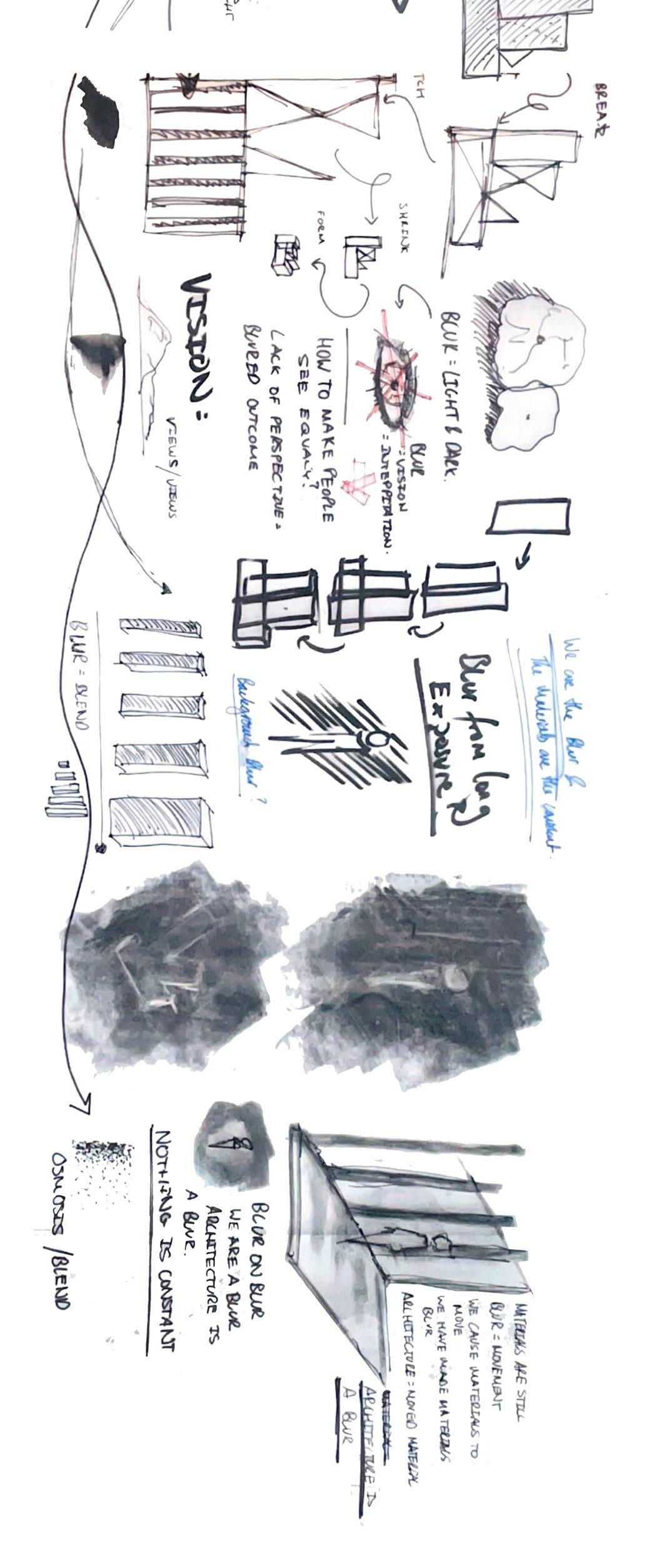
THINKING THROUGH DRAWING: USING THE STRIP TO GENERATE POSSIBILITIES
7
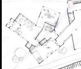
DEVELOPING THE SCHEME
Designing to meet regulations
To ensure the building meets regulatory specifications it is essential to consider this stage ( RIBA Plan of Works stage 5) in the development stages of design.
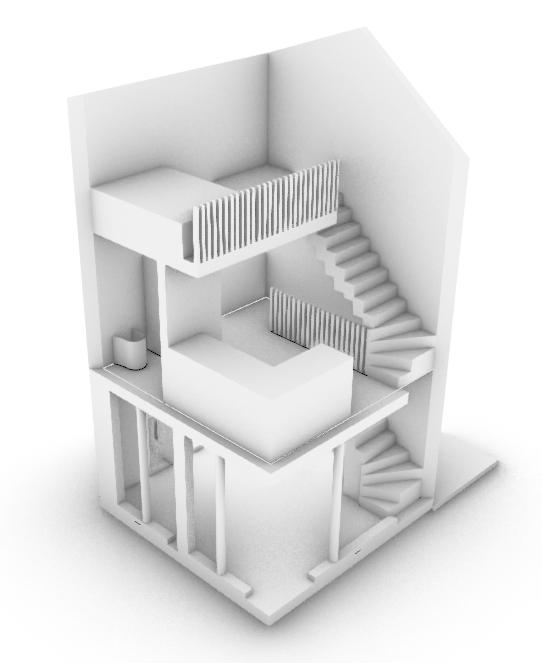
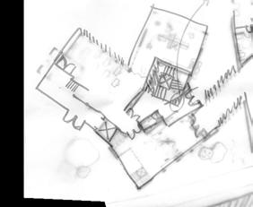
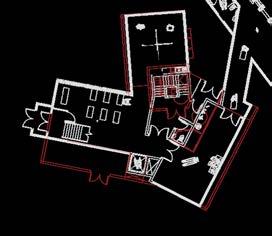
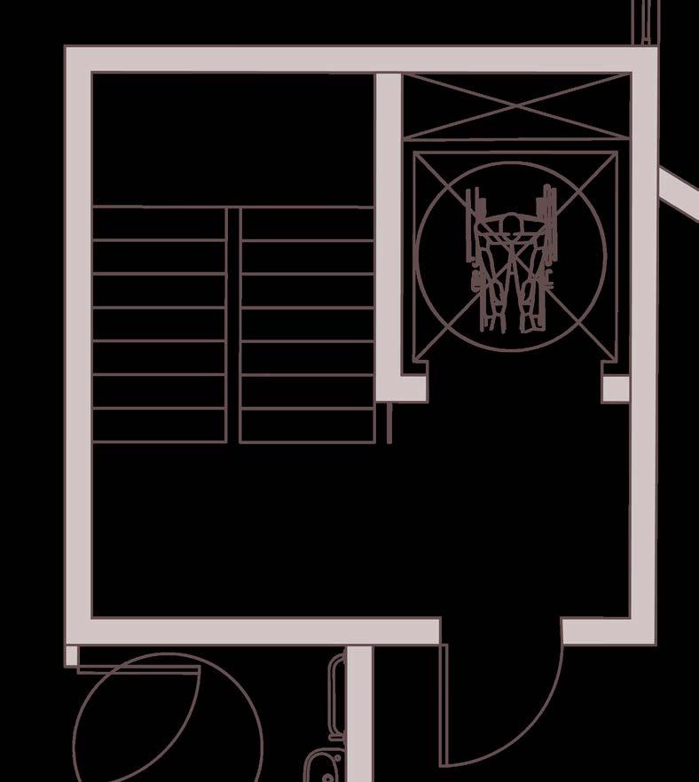
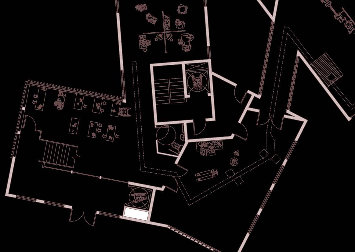
Iterating my intervention to adhere to regulations. To do this I have expanded the central fire core to ensure there is a fire-safe landing and all elements adhere to part B regulations. This design change has affected all 3 floors of the intervention
This adjustment can be seen in the left images where the addition of the fire core has led to the ground floor program changing. The residential entrance has been scaled down as it is used predominantly by the 8 residents and would only need a one-way flow in the case of a fire. This has created more floor area for the workshop & has improved the location of the disabled W.C. as it is no longer facing the entrance & has more direct access to the studio space.
RESPONSE TO CPS:
Predominantly exploring the CPs shown above this development considers accessible use, awareness of regulations and has developed the space to make for more efficient working in all areas of the ground floor.
8
Residential User Worker Public User 1550 mm 1500 mm 1000 mm 1000 mm 1200 mm 1500 mm 4000 mm STAGE 5 CP1 CP2 CP4
Regulations define design
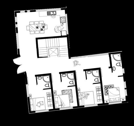
Due to the adaptation of the fire-safe core, the residential strategy has significantly changed.
Although the residential apartment proposed in 3.1 does meet both functional and regulatory specifications (besides the fire stairs) It doesn’t provide a comfortable and liveable environment. This in turn doesn’t meet the common principles CP2 ( creative actors) and CP4 ( Creative programs) and needs significant adjustment to accommodate these principles.
STAGE 4 CP2 CP4
RESPONSE TO CPS:
This development prioritizes the user experience, particularly given the capacity for 8 residents. The design takes into account how the space will function, noting that HMO residents may not know each other before moving in. Consequently, the rooms and en-suites have been expanded to provide ample private space for each individual.
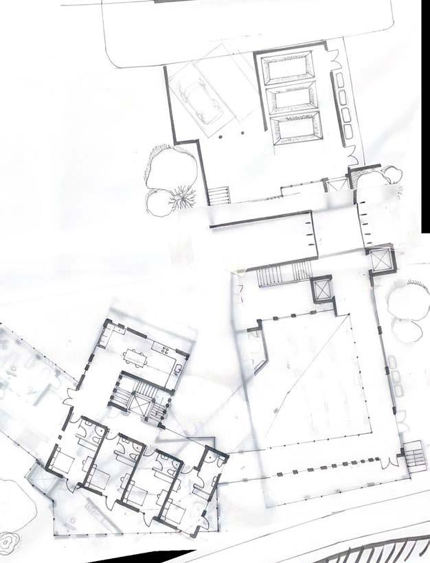
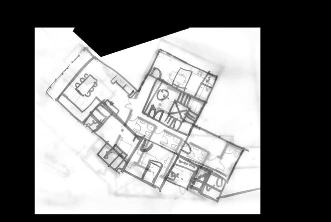
RESIDENTIAL ITTERATION FINDING SPACES
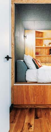
Co-living as an initiative
We-Live - creating a ‘physical social network’
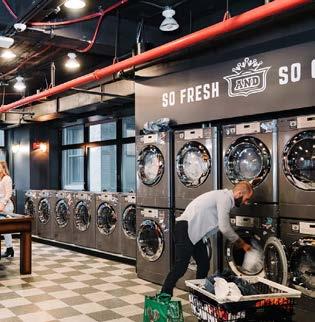
WeLive, serves as a model for fostering community and addressing urban anonymity. This concept informs the design of the second floor of my intervention. By integrating private ensuite bedrooms alongside spacious communal areas such as shared kitchens, lounges, and balconies, residents can clearly distinguish between private and communal spaces. This
FINAL RESIDENTIAL ITTERA TION
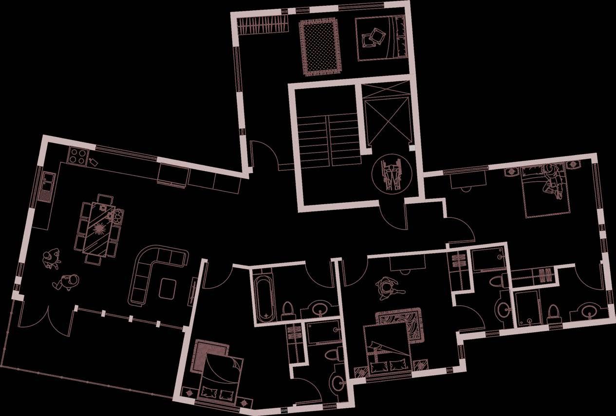
REWORK
RESIDENTIAL
3.1 HAND DRAWN PLAN RESIDENTIAL ITTERATION SKETCH
RESIDENTIAL REWORK
Developing the HMO
The second floor of the intervention accommodates young workers who are taking their first steps into the working world through the intervention program. The floor has been expanded significantly to create a more comfortable environment, capable of housing up to 8 people.
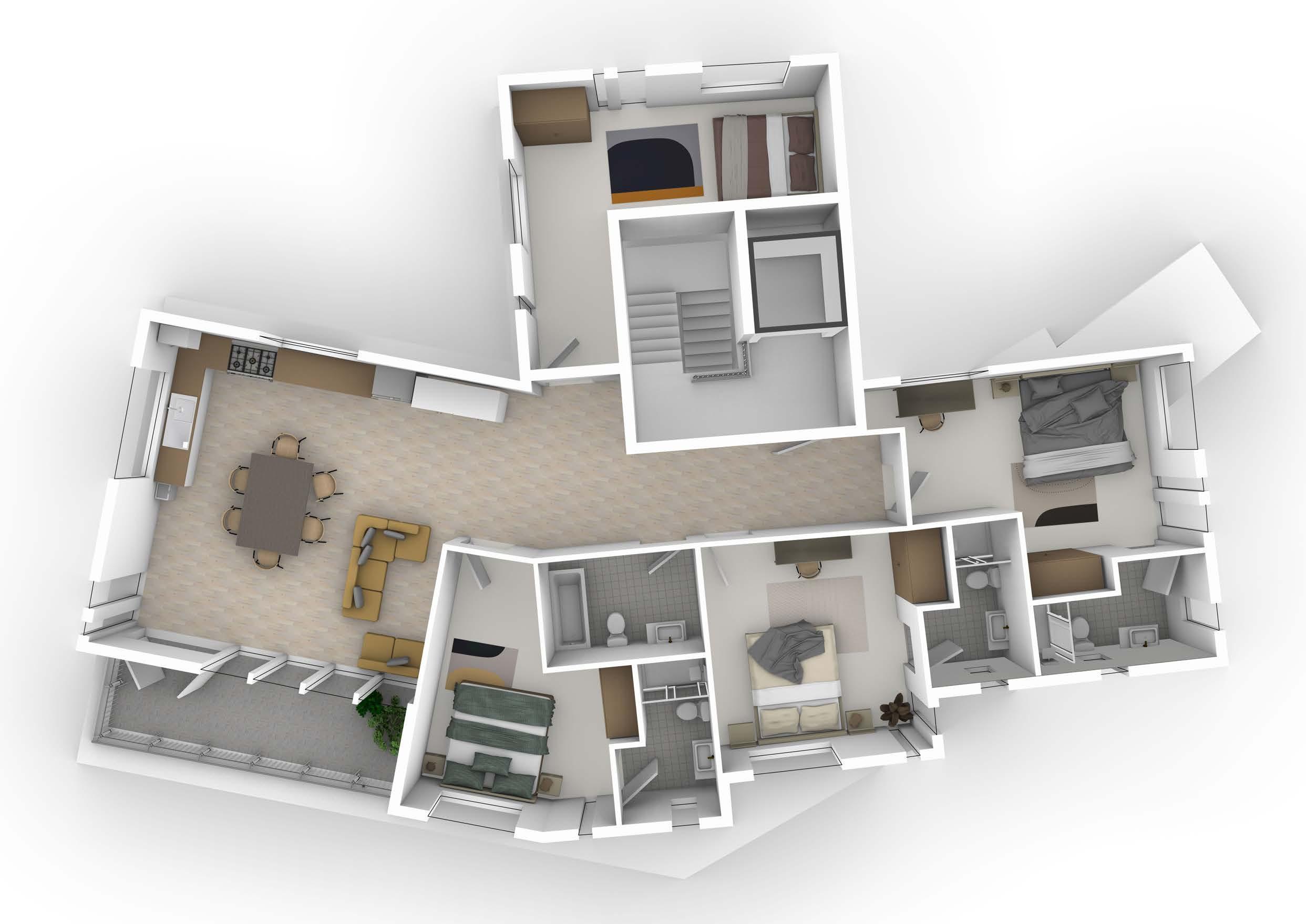
Key drivers for the rework:
- Previous plans lacked sufficient space
- The adapted fire safe core affected circulation in the HMO
- The addition of a south-facing balcony makes the space more enjoyable


3.1 Second floor plans 9
MATERIAL TRANSPORT
Making art accessible
Mechanical strategy that makes the transport of material through the intervention accessible to all.
Incorporating a mechanical transport system not only enhances intervention efficiency but also eliminates restrictions for individual users. This system, akin to a chair lift, employs Bull wheels at both ends to rotate the cable and Riblet Sheaves, ensuring seamless cable movement up and down without disrupting the site walkway.
This element of my intervention responds to CP2 (creative users) as it successfully allows a range of actors to engage. The technologies would require more investigation from an engineer at stage 5 in the RIBA Plan of Works.
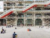
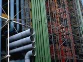
Making mechanics visible: precedent
The Pompidou Centre - 1977 - Paris Richard Rodgers / Renzo Piano
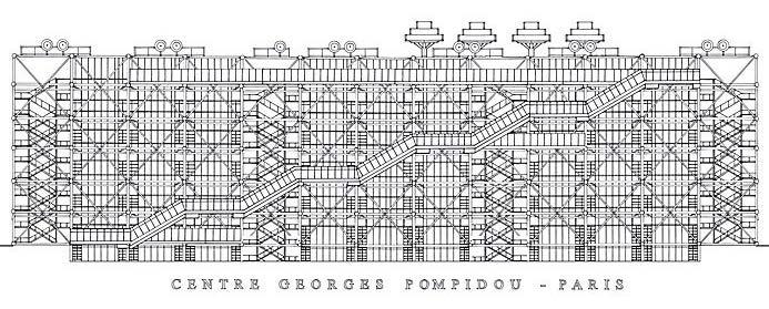
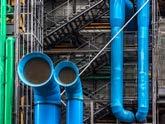
The Pompidou Centre celebrates mechanisms on its exterior maximizing interior space whilst educating and informing users of how the building functions. This is parallel to my intervention where the process is the gallery,
Its celebration of the process has inspired the unorthodox method in my intervention of exposing transport systems to the public on both the interior and the exterior of the building.
DETAILS (not to scale)
All details would need to be confirmed with a mechanical engineer.


11
Depression sheaves
Lift cable
Cable Catcher
breakover sheave
Nut and cotter pin
Evener
Roll back dog
Drive shaft
Lift cable
Leather Break strap
Material Lift: 1000
RIBLET SHEAVE ASSEMBLY
BULLWEEL DETAIL
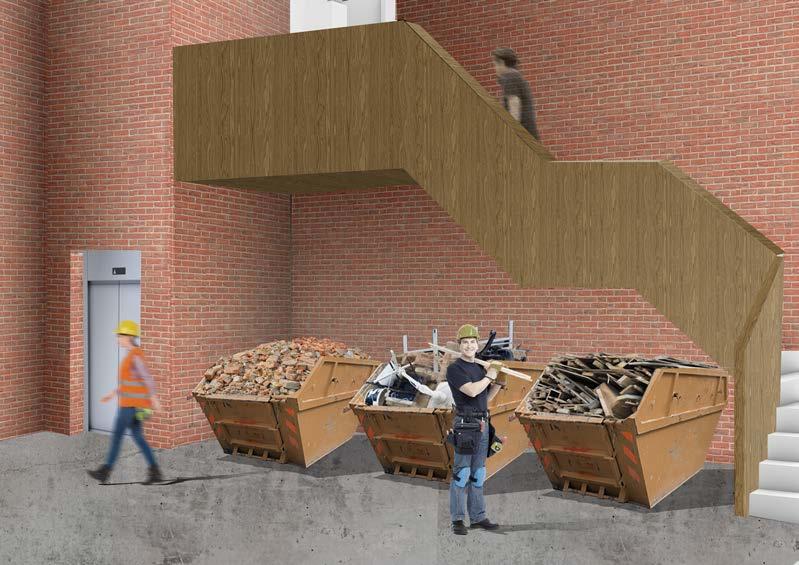
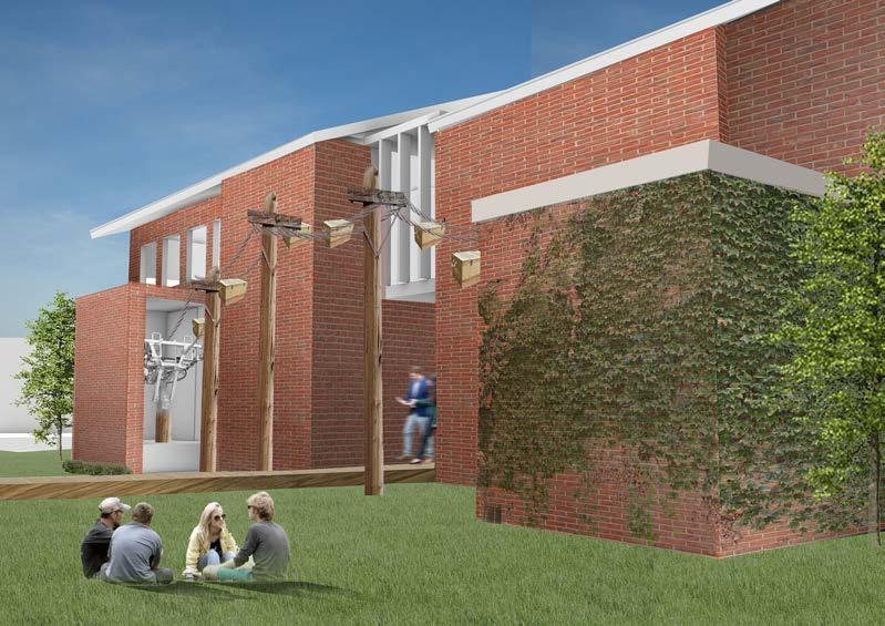
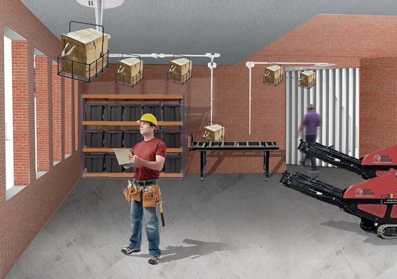
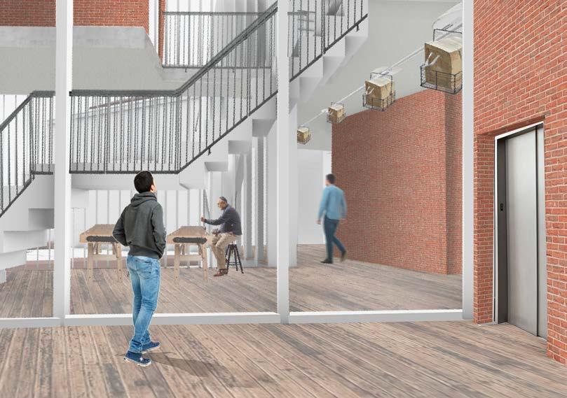
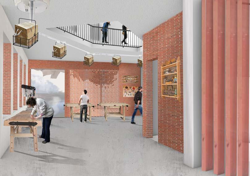
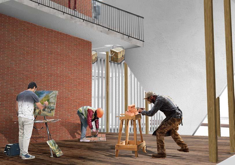
FOLLOW THE MATERIAL A material journey
Using photo-collage to map user engagement following the journey of the material transport mechanism.
These images depict the track enabling boxes/ crates to hang from the ceiling, moving forward/ backward under user control via a remote. The hook mechanism also allows the box to be lowered when the track is stationary.
Integrating this system fosters a more inclusive studio environment, catering to a broader range of disabilities compared to typical studios (as detailed in section 3.1).
CP2 CP3 CP5 CP1 1 3 2 3 4 5 6 2 1 3 4 5 6 12
STAGE 6
DECONSTRUCTION = CONSTRUCTION Design Development
Using the materials from a deconstructed model to develop and improve my design. The new model is now embracing a material-first approach, where the design is shaped by the characteristics and properties of the materials used.
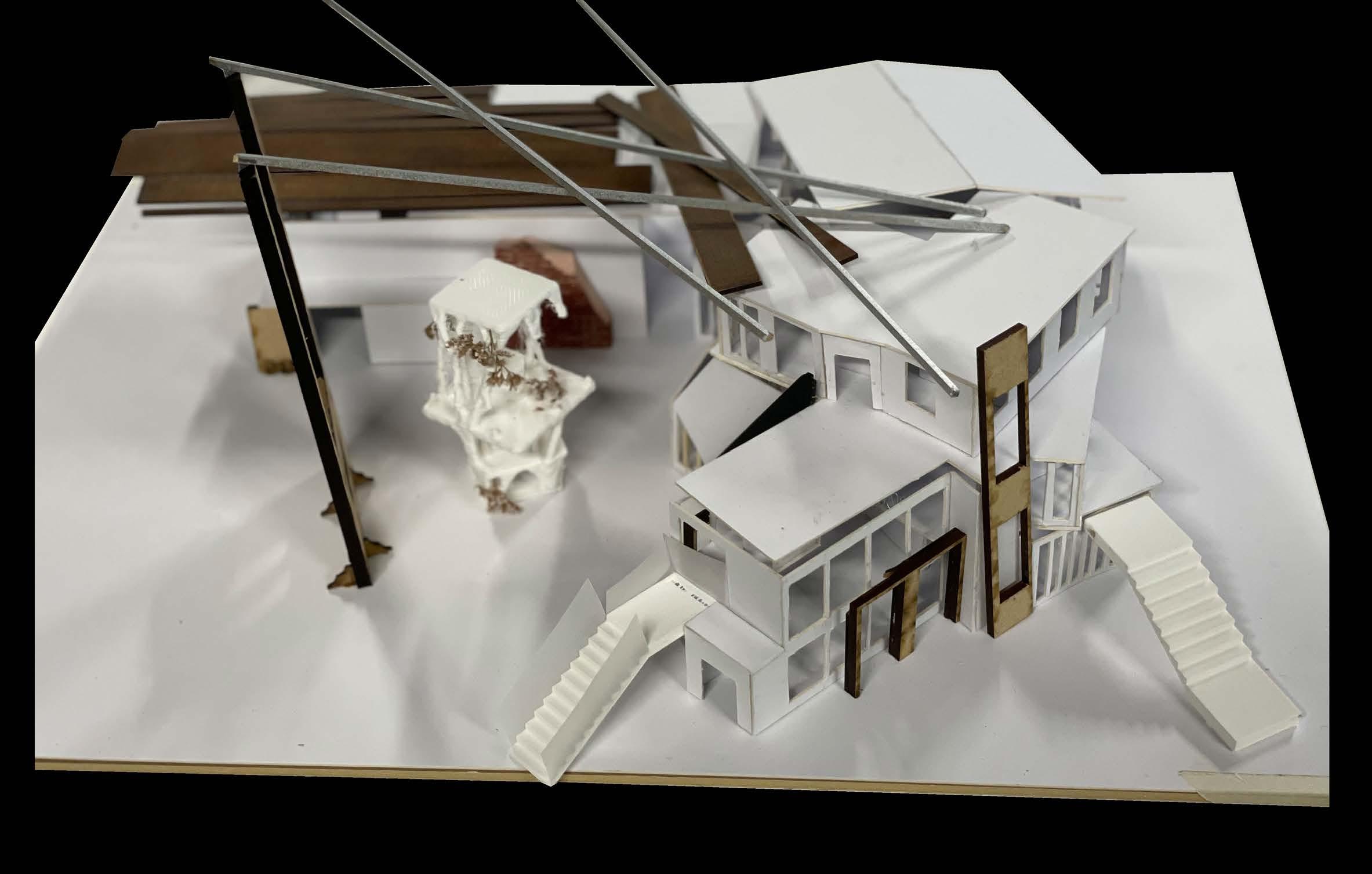
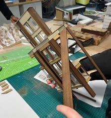
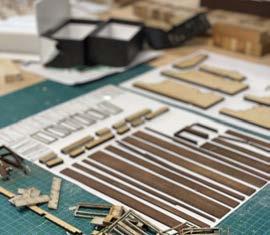
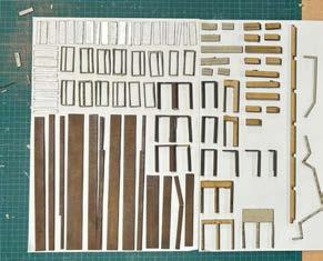
DECONSTRUCTION
Careful deconstruction of a discarded model involves strategically categorizing its parts for re-purposing in new constructions. This process grants a new lease of life to materials that would otherwise go to waste.
13
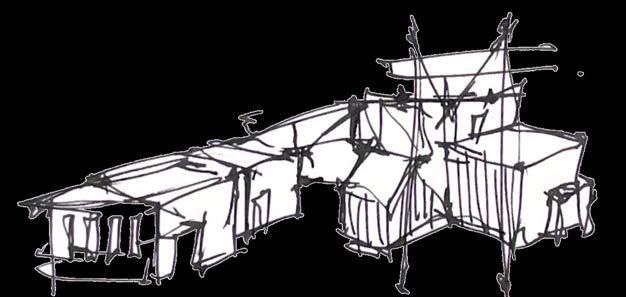
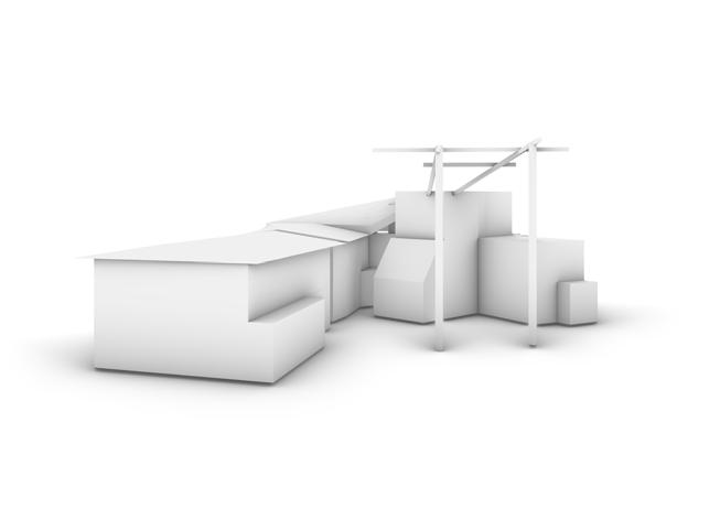
MATERIAL FIRST
Material defines form
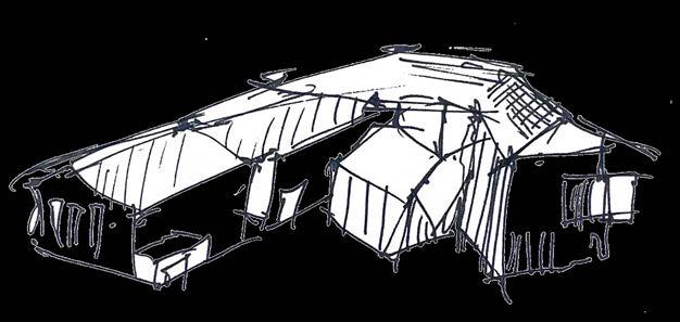
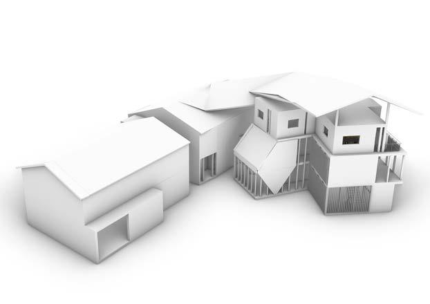
Using the principles of deconstruction to reconstruction I have attempted a new roofing strategy.
ROOFING ITERATIONS
Using the reconstructed model as form inspiration I have considered possible roofing iterations but have decided to continue with a similar strategy as 3.1 as it is the least material consuming therefore minimizing embodied carbon in the building.
RESPONSE TO CPS:
This development prioritizes protecting common resources and creatively utilizing materials without overuse. Additionally, the intricate roof detailing would have required more new materials and labour, which does not align with the commons scheme.
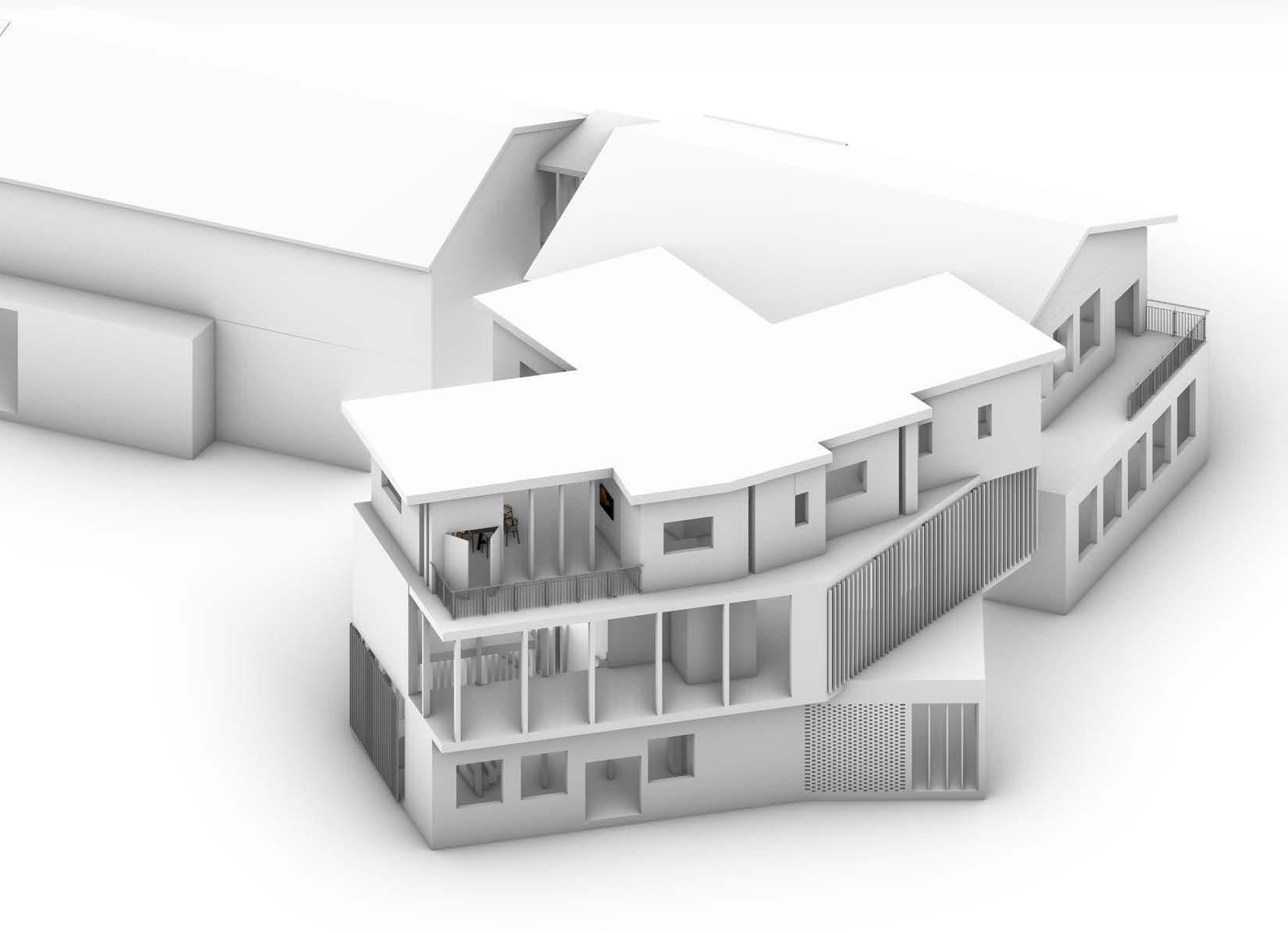
ROOFING STRATEGY
Although the form hasn’t been directly inspired by the ‘reconstruction’ the materiality has. Where possible the design will include recycled and re-purposed elements in both structure and form.
STAGE 4 CP3 CP5
14
MAPPING SHEFFIELD
Waste Circuits
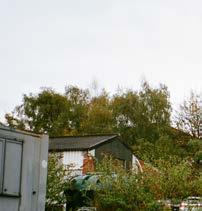
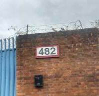
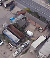
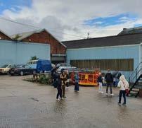
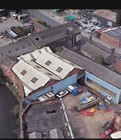
Utilizing the buildings scheduled for demolition on the site master-plan, I have identified a new waste circuit.
Using the principles of the model workshop on a larger scale, I have highlighted the buildings that would be demolished for the site plan and have hypothetically dissected the buildings to categorize ‘waste’ that would be suitable to be re-purposed or reused as construction material in my intervention.
Based on educated assumptions, I have estimated both the wall construction and structural aspects of each of the proposed buildings.

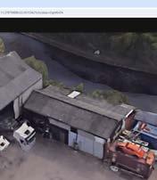


- Corrugated steel
- Steel frame
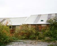
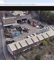

- Corrugated steel roof
- Plastic gutter system
- Brick structure
- Brick cladding
RESPONSE TO CPS:
Considering manufacturing and construction, the choice of materials has led to using locally sourced options, thereby limiting transport and minimizing embodied energy. Employing local materials, contractors, and workers ensures that the project contributes to and benefits the community.
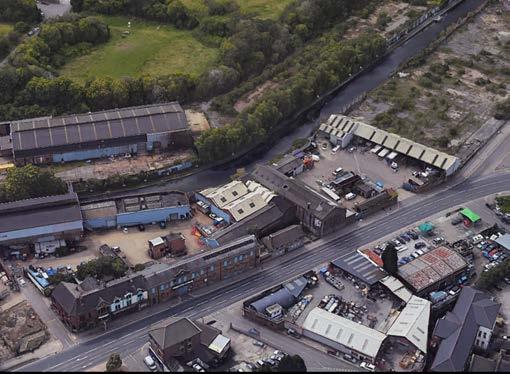


- Brick structure
- Lead Tilled roof
- Wooden rafters
- Plastic guttering


- Corrugated steel roof
- Brick structure
- Brick Cladding
- Plastic guttering
- Corrugates steel skin
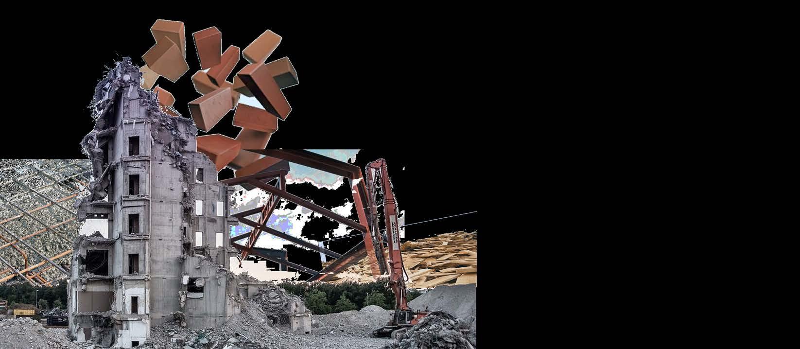
THE CONSEQUENCES OF DEMOLITION
A discussion of embodied carbon
Demolishing buildings carries significant consequences in terms of embodied carbon. When structures are demolished, a substantial amount of embedded carbon from the building materials and construction processes is released into the atmosphere. This release contributes to carbon dioxide emissions, exacerbating climate change. Moreover, demolition often necessitates the use of heavy machinery and is an energy-intensive process, further increasing carbon emissions. Using reclaimed material from demolitions and re-purposing an existing building is how I combat this in my intervention.
Images taken on site Google earth Structure & wall build up Materials
Intervention structure consideration
STAGE 6 CP1 CP5
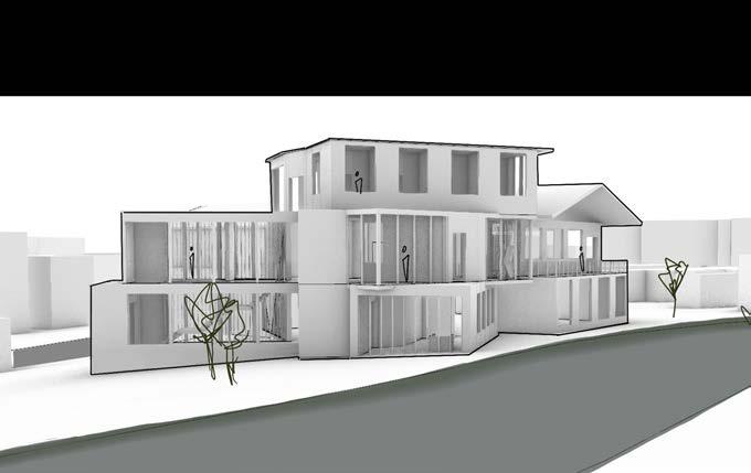
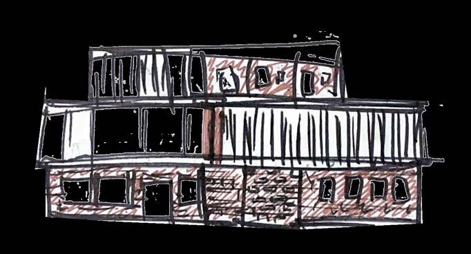
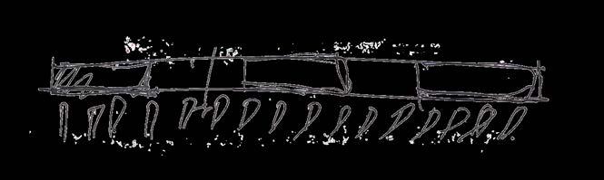
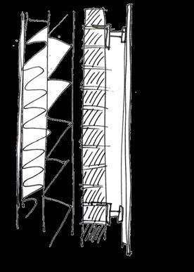
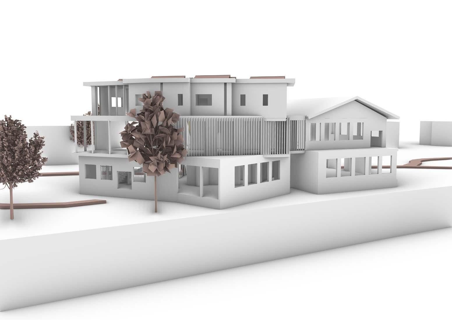
Using the defined window glazing percentage from authors technologies C of 20% as optimal for radiation and daylight facto, I have applied a shading strategy to the South facing facade which will significantly reduce the daylight factor from its previous design.
The new strategy consists of using recycled steel sheets attached to the exterior of the facade which act as a shading
OPERATIONAL USE
User Comfort & experience
Using knowledge acquired from testing in technologies C as a basis I have iterated facade shadings elsewhere in the intervention to optimise radiation.
RESPONSE TO CPS:
To ensure the commons is an enjoyable place to visit, user comfort has been prioritized. The manipulation of light within the commons enhances the experience for all users while also reducing energy usage and building costs through the effective use of natural resources.
16
taken from authors Technologies Part C Lucy Lees (2024) BA3_Tech_PartC_rchitecture_ Lees_Lucy. 1CWK50: Technologies 3
Image
CP4 CP3
STAGE 7
ENVIRONMENTAL STRATEGIES
Climate response
A section to facilitate an environmental strategy diagram making note of lighting, heating, ventilation & drainage strategies to promote optimal user experience.
Passive ventilation will be used in all rooms where there is no use of industrial machinery however in the drop-off room, the processing room & the workshop industrial ventilation will be required.
The systems proscribed for the building combat social concerns of the climate crisis whilst simultaneously promoting cheaper living through accessing heat and water resources provided on site.
HEATING STRATEGY:
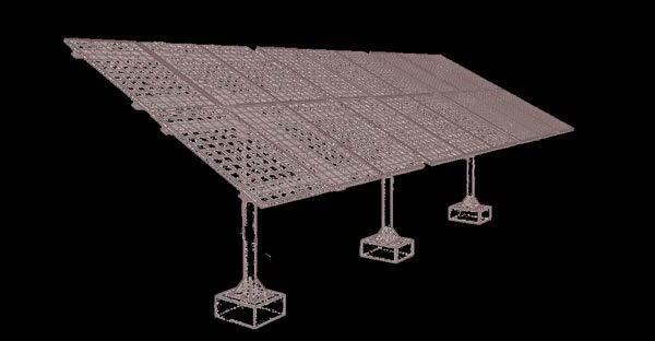
Because of its size, the building uses mechanical heating and cooling efficiently. It combines solar panels on the flat roof, facing south for maximum energy absorption, with a water source heat pump in the agent canal.
RAINWATER STRATEGY:
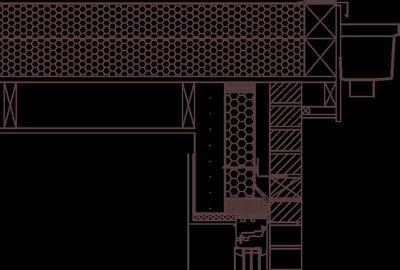
Bellow shoes the flat roof strategy and drainage system. This drainpipe will lead to a rainwater collection point used for watering plants and cleaning the building exterior.
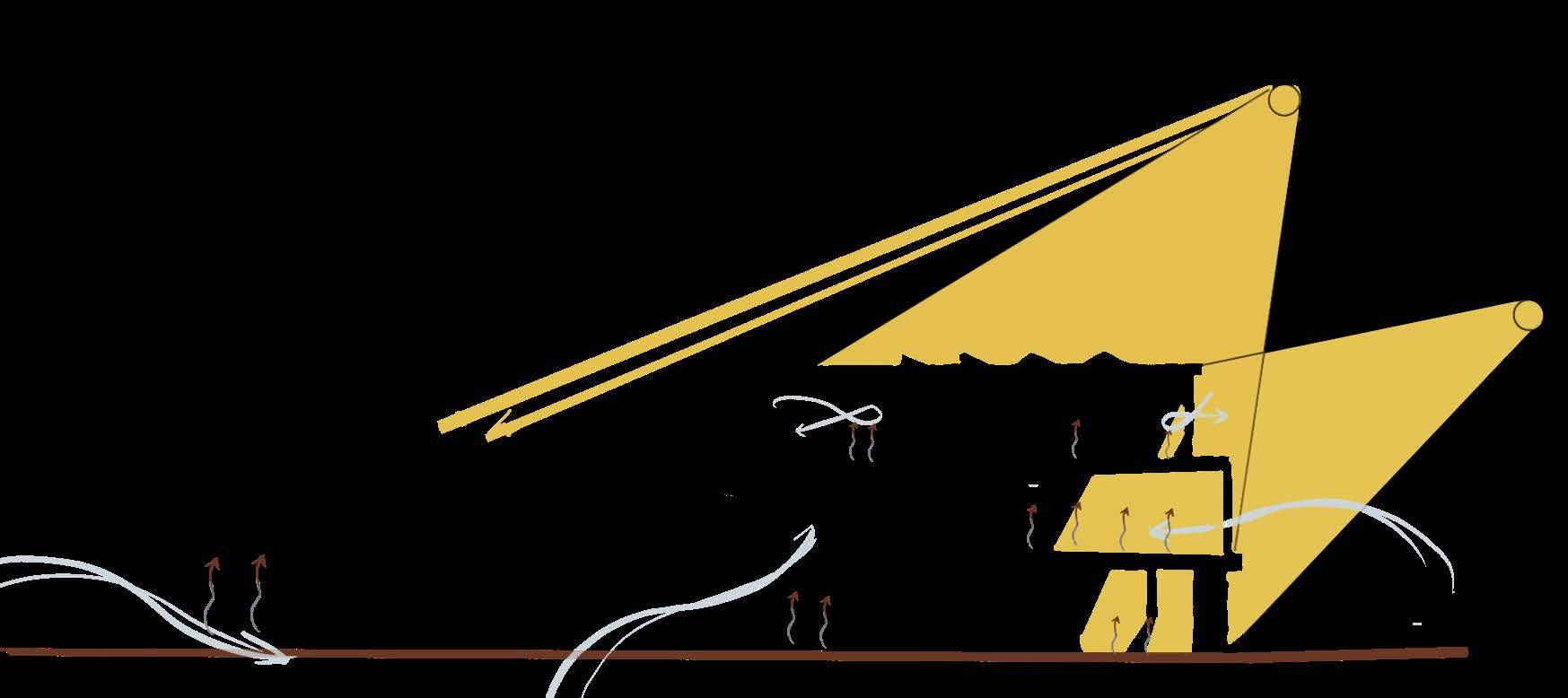
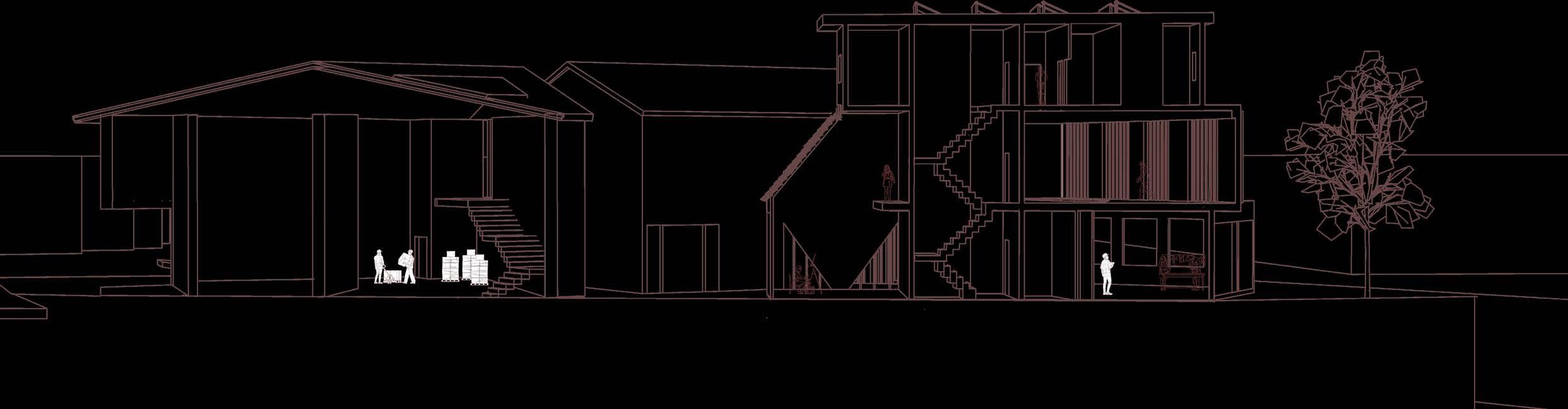
KEY: Rain water Sun path Natural Ventilation Heating /cooling Electric suply from heat sourse water pump
Winter
STAGE 7 CP5 CP3
Summer solstice
solstice
EXPERIENTIAL DETAIL
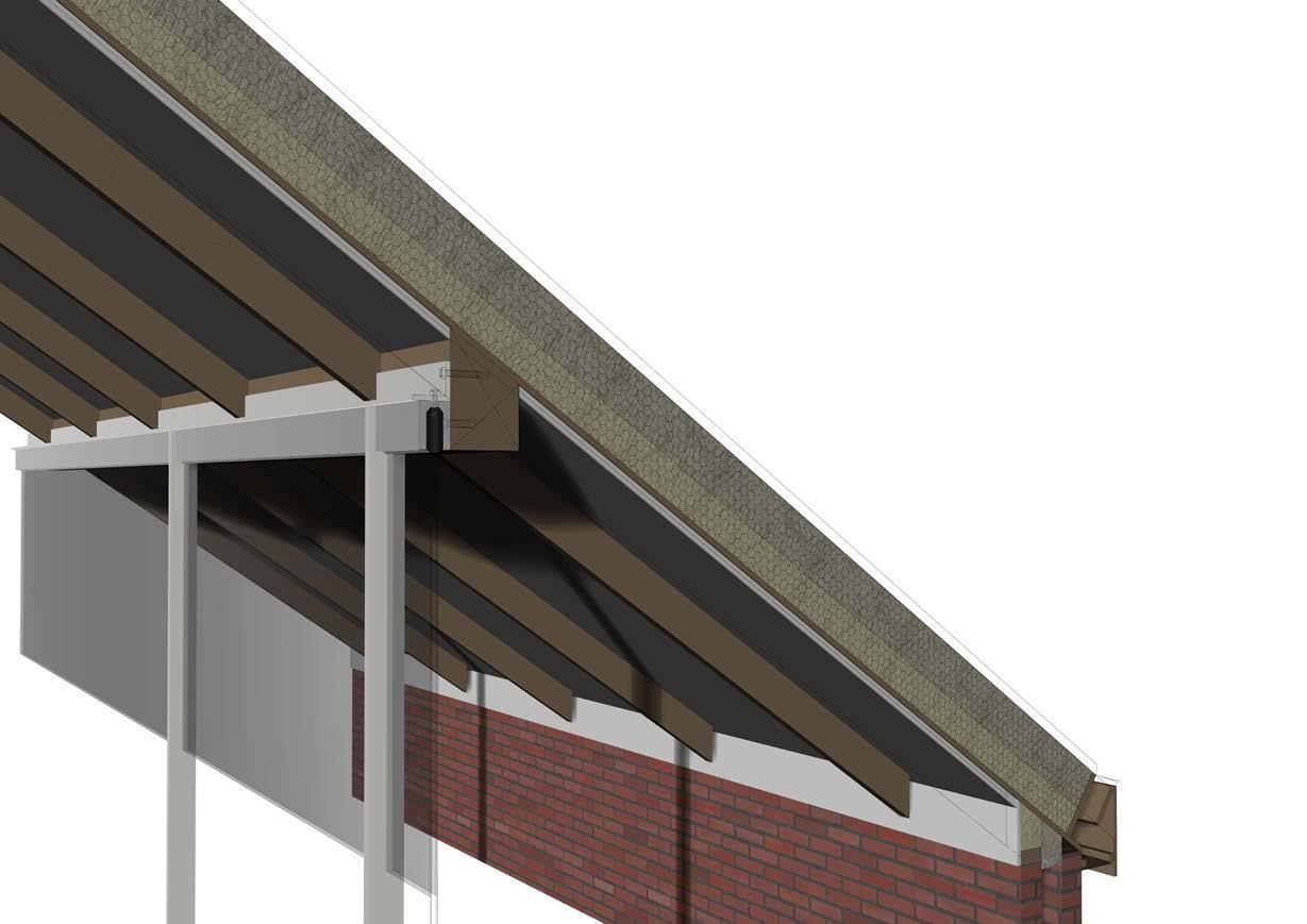
1:5 VIEWING THE CYCLE
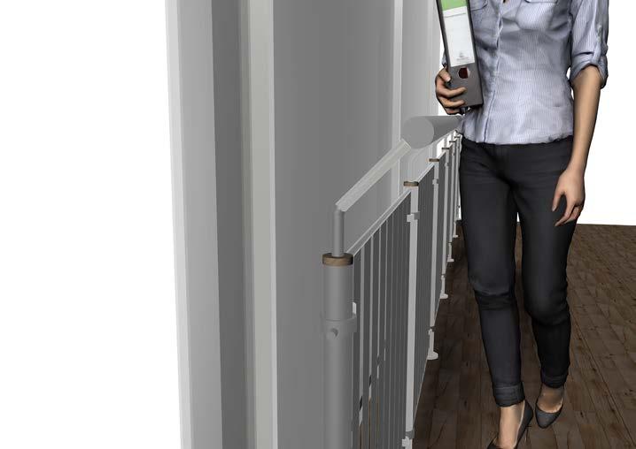
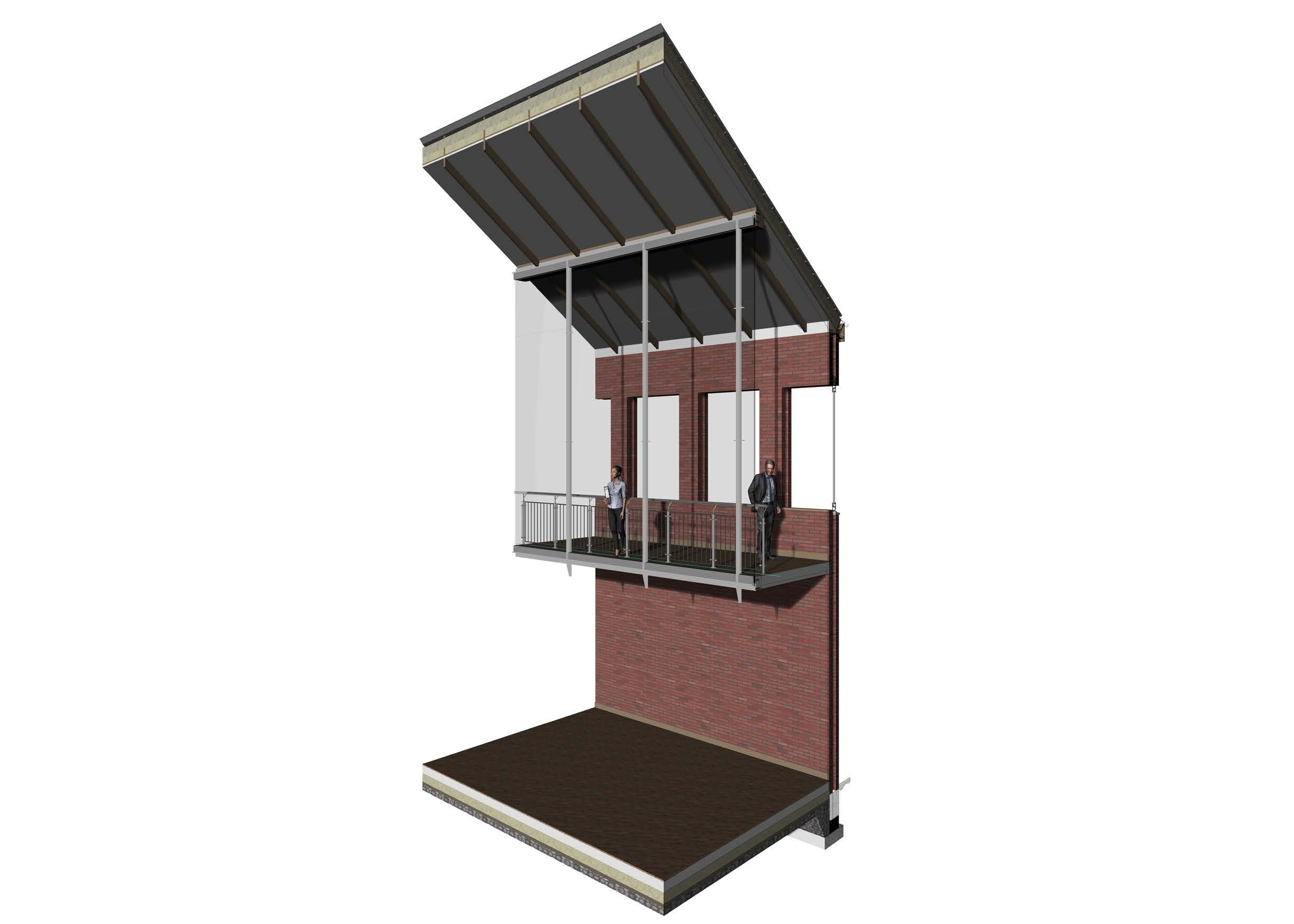
This section focuses on user experience, highlighting the safety features of the walkway. The glazing and handrail components effectively shield users from harmful fumes and potential hazards associated with industrial work below, ensuring a secure environment.
1. Exposed rafter beams
2. Metal plate bolted to the joist
3. Aluminium glass fixing
4. Silicone
5. Fixing bolted to Joist
6. Reclaimed corrugated steel sheets from the existing building
7. Horizontal Battens
8. Breather membrane
9. Two layers of rigid insulation
10. Vapour control layer
11. Plywood decking
12. Wooden horizontal joist
13. Aluminium glazing support
14. Glazing
15. 40mm diameter metal handrail
16 . Recycled rebar fencing
17. 200mm gap between glazing and handrail.
RESPONSE TO CPS:
This system enables users to safely and pleasantly observe the mechanical systems. With the banister utilizing recycled rebar, it also serves as a tangible demonstration of how construction waste can be re-purposed.
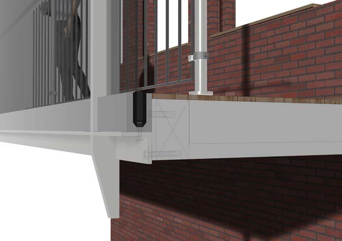 18. Intermediate floor supported by Steel frames.
19. Metal plate bolted to the horizontal beam.
20. Aluminium glass fixing
21. Silicone
18. Intermediate floor supported by Steel frames.
19. Metal plate bolted to the horizontal beam.
20. Aluminium glass fixing
21. Silicone
the
1 2 3 3 4 5 6 7 8 9 10 11 12 13 15 14 16 17 16 18 22 20 21 19 STAGE 7 CP4 CP1 CP3
22. Metal Banister bolted to
floor
18
DETAILED SECTION 1:5 scaled to fit page
A detail section to demonstrate wall build-up and detailed connections. Recycled bricks are used to construct cladding and the steel frames are recycled steel from buildings on site. At points of typical steel and brick build the U value is 0.16 W/m2K
1. Powder-coated recycled rebar handrail
2. Paving slabs on pedestals
3. Rubber layer
4. Vapour control layer
5. Insulated tilting fillet
6. Plywood decking
7. Timber joist cavity
8. Plasterboard
9. Coping stone
10. Drainage system
11. Aluminium window frame
12. Insulation & plasterboard
13. Insulated cavity barrier
14. Running bond brickwork
15. Glazing
16. Aluminium window frame
17. Glazing
18. Plasterboard & finish
19. Timber battens
20. Timber Lintel
21. Insulation
22. Rigid insulation
23. Weatherproof cladding to engineers’ specification
24. Steel frame
25. Insulated cavity barrier
26. External brickwork
27. Facing brickwork
28. Air gap
29. Breather membrane
30. Insulation
31. Steel frame stud work
32. Vapour control
33. Plasterboard
36.
38.
42. Reinforced concrete footing
19
34. Plywood 35. Vapour control layer
Rigid insulation 37. Concrete slab
Damp proof course
39. Sand binding
40. Densely packed gravel
41. Foundation blocks
1 2 3 4 5 6 8 7 9 10 11 12 13 15 16 17 18 19 20 21 24 22 23 25 26 27 28 29 30 31 32 33 34 35 36 37 38 39 40 41 42
A TOUR OF THE STUDIO
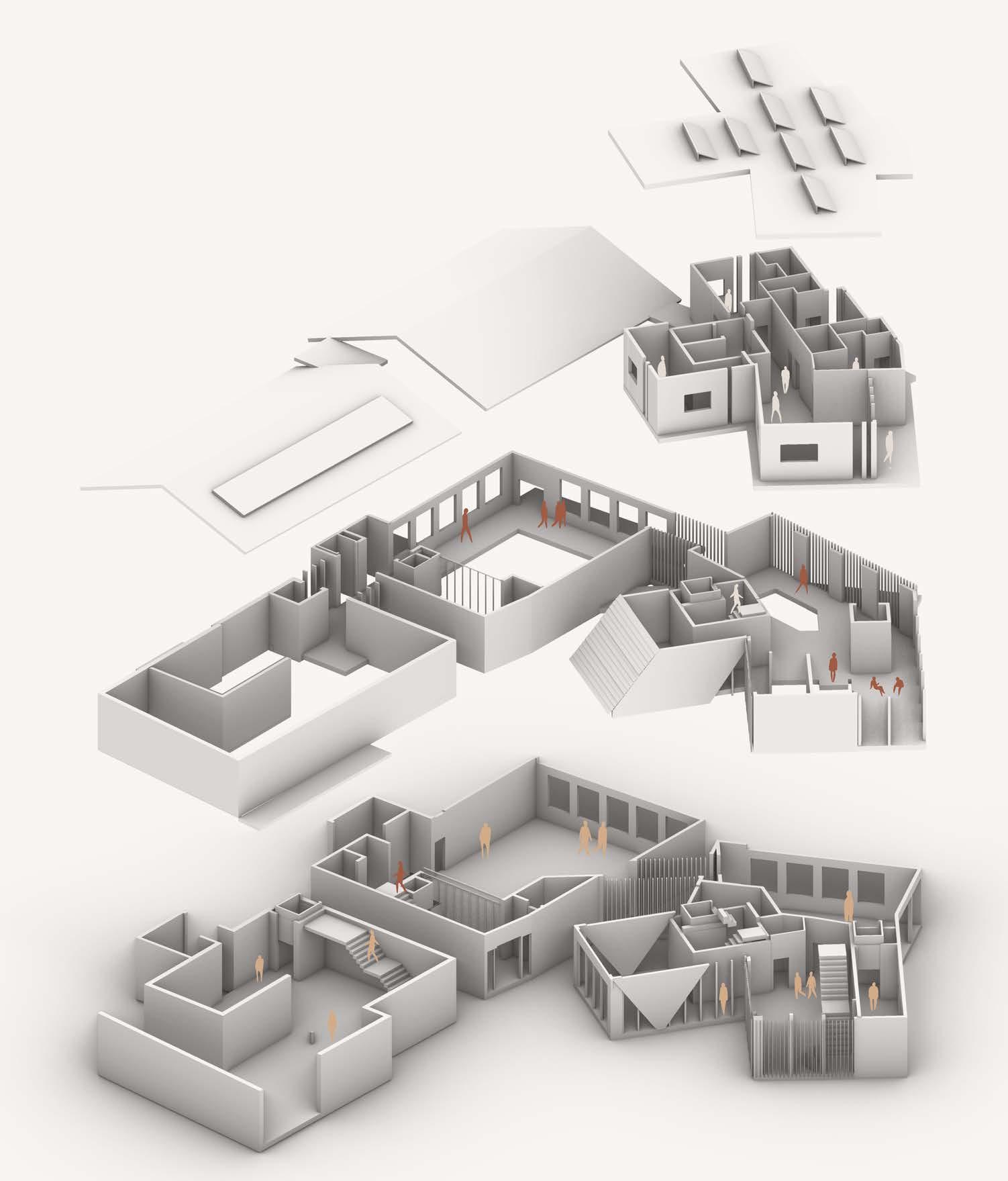
Intervention programme
RESIDENTIAL
An apartment housing up to 8 workers from the intervention.
PROMENADE
A walkway adjacent to multiple double height spaces which display the processing & development of waste below.
CLASSROOM 2
A smaller classroom or group studio for larger projects.
PROCESSING
Material is received via the mechanical lift and is taken to be processed by being crushed, cleaned shaped etc.
THE ‘TIP’
Cars/Vans are encouraged to drive through and drop of construction waste. The material is sorted, stored and is transported to the processing area of the intervention.
WORKSHOP
Material is processed by individual artists in a room equipped with drills/sanding machines/tools etc.
STUDIOS
Space for 4 permanent individual artists who create art and sculpture from waste that will be displayed in and around site.
CLASSROOM
An area adjacent to the user exit filled with workshop benches and stools that can be used personally or as a classroom.
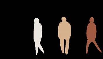
Residential User
Intervention worker
Public user
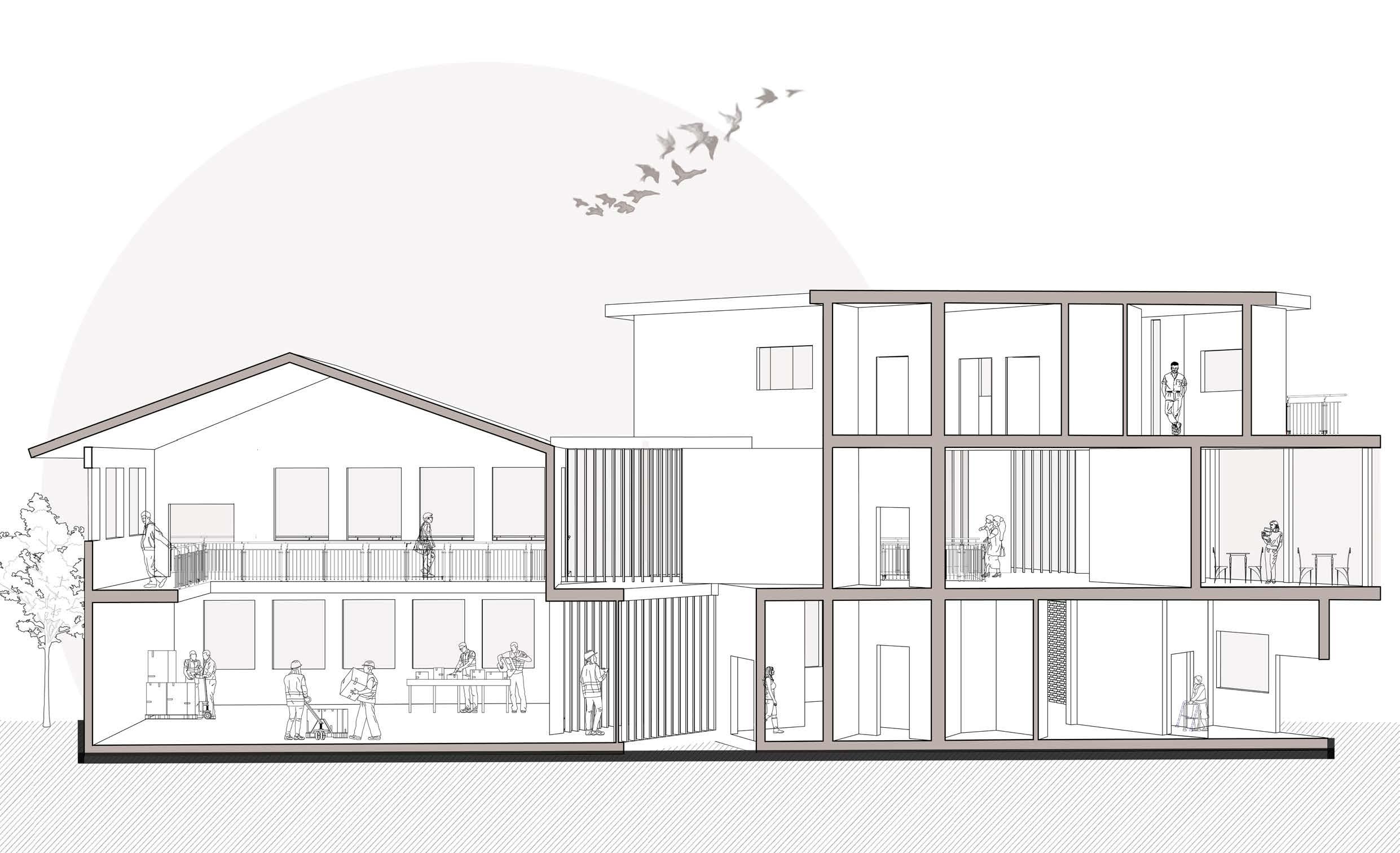
A DAY IN THE STUDIO
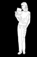
Mapping User engagement
Using a section to determine user engagement with the intervention. Considering CP2 and Plan of Works Part 7 ( Handover and effective use of the spaces )
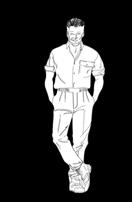
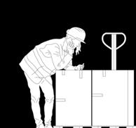
The three colours below represent the primary approaches to this intervention. As outlined in the section, these approaches align with the floor levels where users are situated. The program detailed in section 3.1 highlighted the necessity of a clear boundary between private and public spaces, which has been successfully implemented through the floor changes.
RESIDENTIAL WORKER PUBLIC USER
21
A DAY OUT OF THE STUDIO
Mapping extended
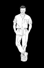
Considering the wider effects of my intervention by mapping the course of each of the three target groups.
RESIDENTIAL WORKER
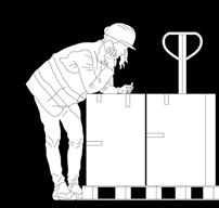
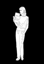
Mapping the extended users interact with the surrounding area of the site. This gives a sense of how long the users would be on site as well. Where public users may come for a day trip, intervention workers & those living on site would be based in and around the site meaning they will engage with the local spaces and buildings more. Attercliffe Road gives users direct access to the city centre and the site has access to canals, rivers, and green space walks.
22
PUBLIC
River Don Open space Sheffield hallam University City Athletics centre Effinghamrd Atterclifferd Open space CADS Local brewery Attercliffe rd Open space Stevenson rd Attercliffe tram Attercliffe tram TinselyCanal Staniforthrd CorbyStreet Running water Green space SHEFFIELD CITY CENTRE Residential Residential
USER
MASTER-PLAN
No building exists in isolation
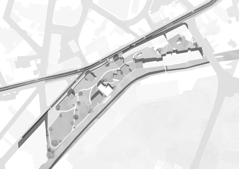
Displaying how my intervention interacts with other interventions on site.
THE UTENSILS OF SHEFFIELD:
Applying waste-to-product principles akin to my intervention, this project transforms scrap metal into cutlery usable in the ROB&HOOD initiative. Additionally, it serves as an educational centre highlighting Sheffield’s history, forging connections between the local community and our site. Located adjacent to my intervention, this shared area evolves into a bustling courtyard of production, offering skill-building workshops and educating individuals of all ages and backgrounds on waste management post-end-of-life.
EDUCATION CENTRE:
Seeking to educate teenagers through innovative crop experiments, this building bridges a gap with a demographic that my intervention doesn’t directly reach, creating a fresh connection within the local community. To further engage, sculptures strategically placed around this educational initiative can spark meaningful discussions and interest in my intervention. This pioneering building serves as an early focal point, surrounded by crops and farmland signposting the green initiative of the site.
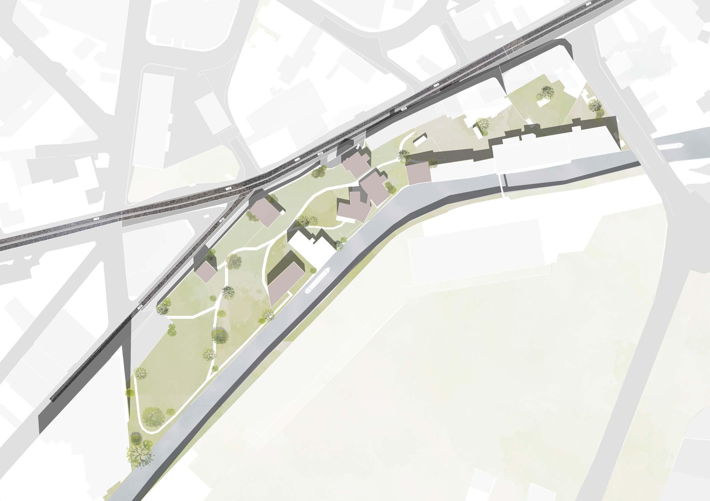
ROB&HOOD:

Crafting a hotel and restaurant experience centred around a connection to nature offers a compelling narrative on-site, contrasting with my intervention to showcase diverse approaches to the climate emergency. Food outputs from this experience could be featured in my intervention’s seating area, encouraging discussions and ideally inspiring visitors to explore both initiatives.

THE VALUE OF A REFUGEE:
A residential scheme prioritizing a support system for refugees serves to integrate newcomers into Sheffield’s community fabric. The complementary interventions in the vicinity generate job opportunities and educational elements, facilitating refugees’ engagement with the broader community. My intervention, can teach transferable skills, and equip individuals for success beyond this project. Acting as a secure hub, the site fosters connections and aids refugees in transitioning smoothly into wider society.
THE SITE BECOMES A CREATIVE COMMONS:
The interventions synergize, fostering a site that deeply engages with all the common principles. This site underwent meticulous analysis through stages 1 to 4 of the RIBA plan of works in 3.1, and this master-plan aligns with Stage 7, facilitating an effective handover to users for optimal space utilization. Achieving this involves ensuring that the various interventions complement each other, fostering a non-monetary economy on site.
5m 10m 20m 30m
CP4 CP1 CP5 CP3 CP2 STAGE 7 23
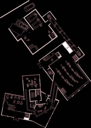
GROUND FLOOR PLAN
Scale 1:100
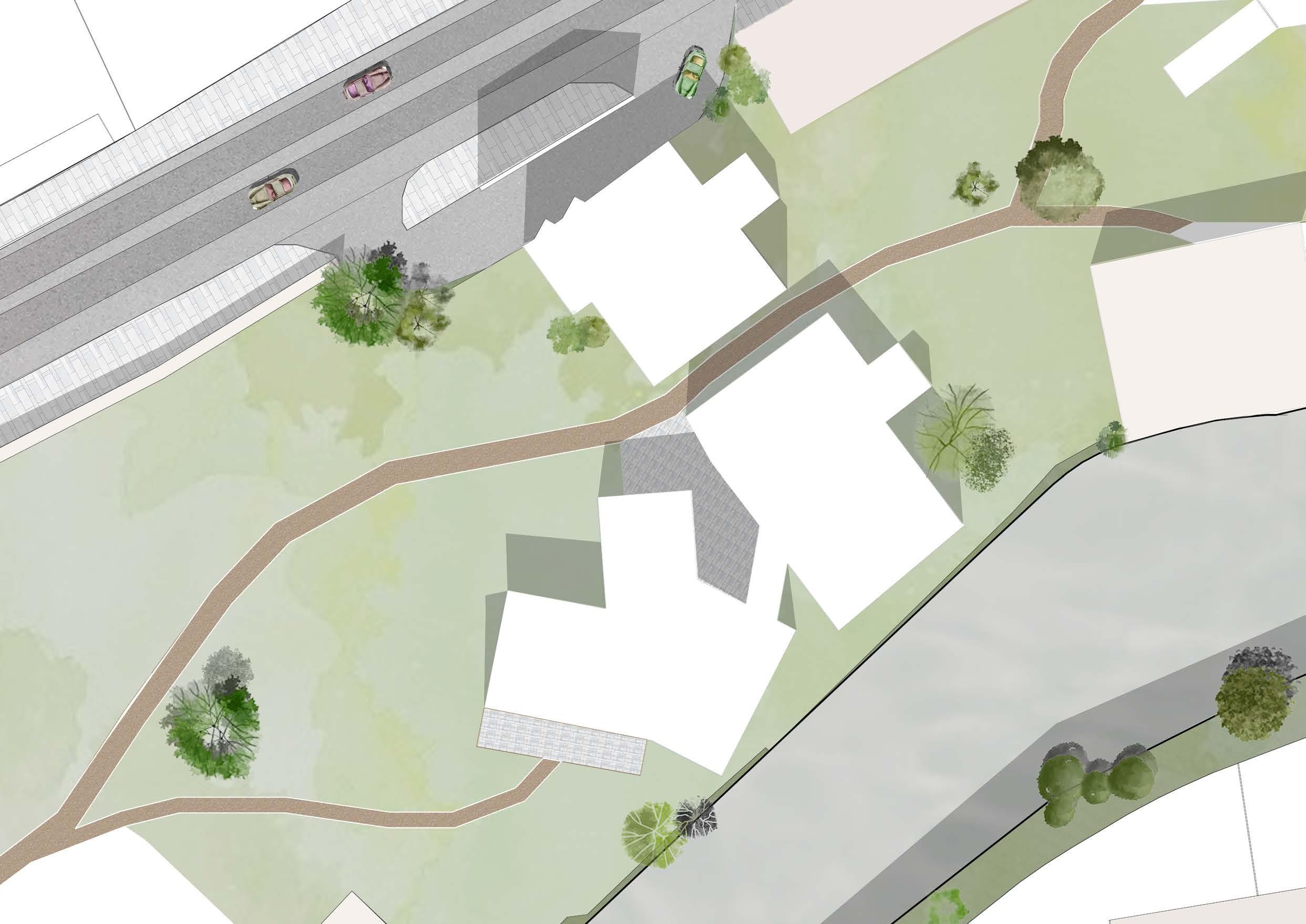
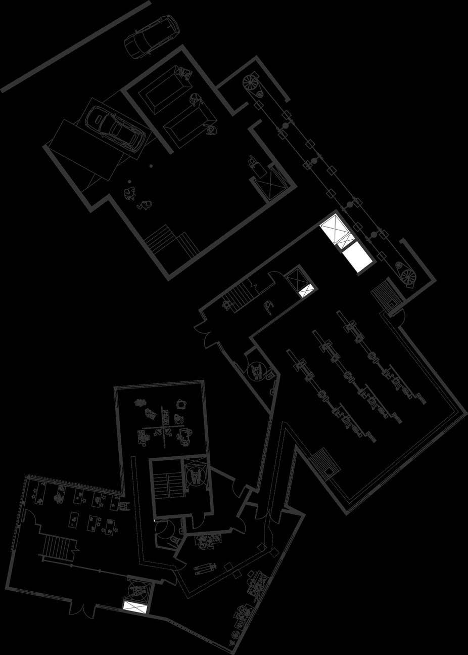
3 1 1. Viewer entrance 2. Residential entrance 3. Waste drop off 4. Waste store and organized 5. Entrance to transport mechanism 6. Staff lift 7. Staff stairs 8. Mechanical material transport system 9. Material drop off and sort 10. Material processing 11. Mechanical material transport 12. Material workshop 13. Education space 14. Studio spaces 15. Disabled access W.C. 16. Disabled access W.C. 17. Viewer entrance foyer 18. Viewer exit foyer 19. Fire-safe core 20. Viewer lift 21. Private foyer 2 4 5 6 7 8 9 10 11 12 13 14 15 16 17 18 19 6 20 20 21 The ground floor program demonstrates the material journey through the intervention.. 1.5m 3m 6m
FIRST FLOOR PLAN
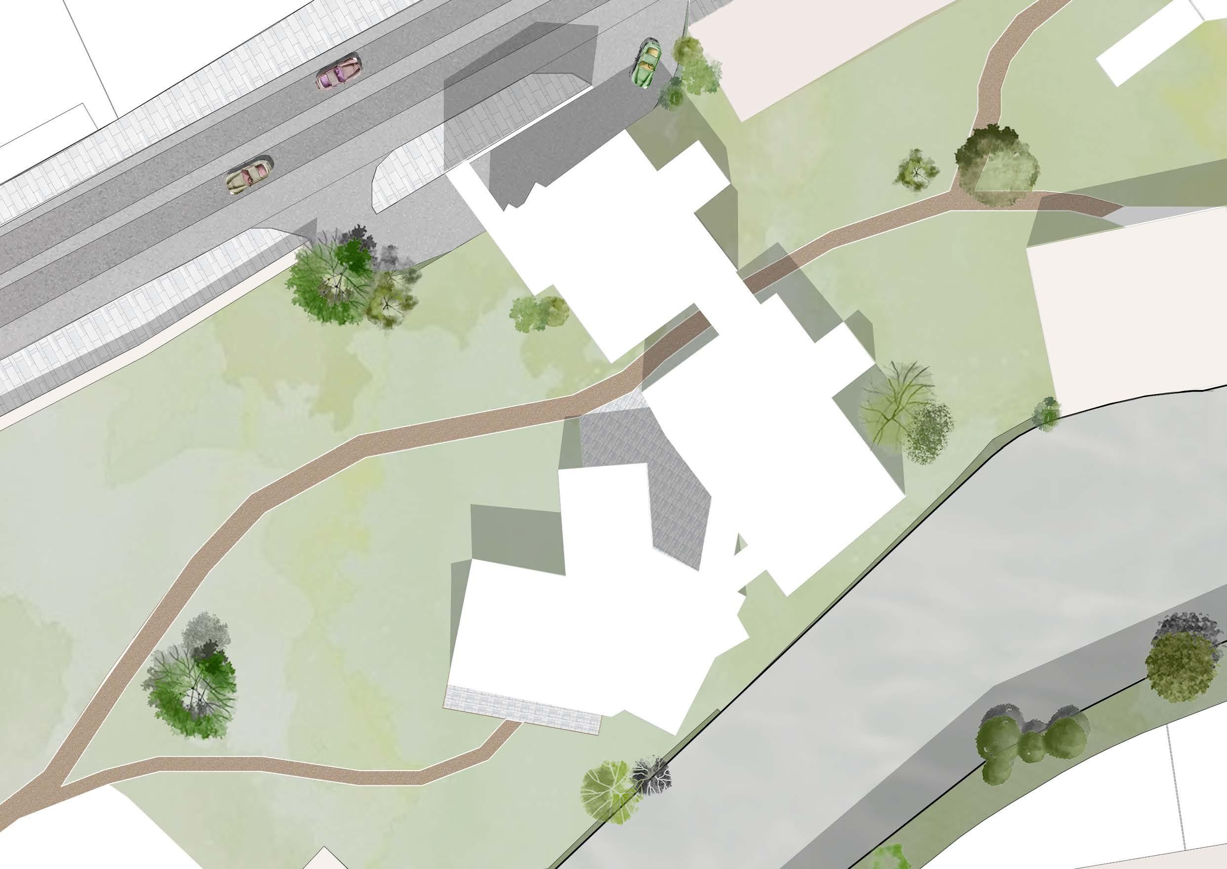

1. Viewer foyer 2. Viewing balcony into industrial space 3. South-facing balcony 4. Workshop viewing walkway 5. Studio viewing platform 6. Teaching space viewing platform 7. Seating area with snack stall 8. Fire-safe core 9. Stairs leading to the exit foyer 10. Art studio & Classroom space 11. Staff walkway 12. Staff stairs 13. Staff lift 14. Store - pamphlets & program explanations The first floor focuses on how the user views the production 1.5m 3m 6m 1 2 3 4 5 6 7 4 8 9 10 11 12 13 13 14
Scale 1:100
SECOND FLOOR PLAN
Scale 1:100

The second floor is private for the residential apartment capable of housing up to 8 people.
7. Bedroom 3 - with en-
8. Bedroom 4
9. Communal bathroom & bath/shower
10. Corridor access to fire escape - all bedrooms within 8m of fire escape (part B)

1. Fire-safe core 2. Residential entrance 3. Kitchen & communal space 4. South-facing balcony
Bedroom
with ensuite & shower
5.
1 -
suite
shower
6. Bedroom 2 - with en-
&
suite & shower
1 2 3 4 5 6 7 8 9 1.5m 3m 6m 10 26
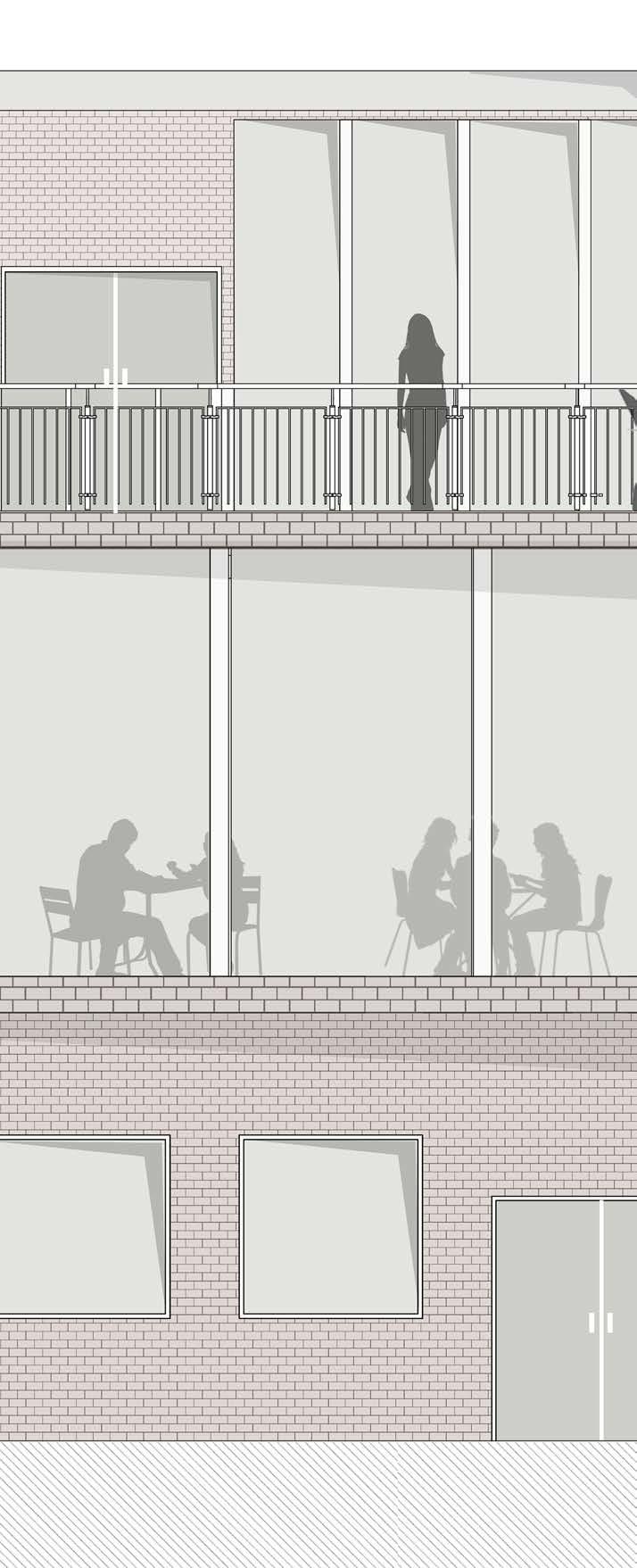
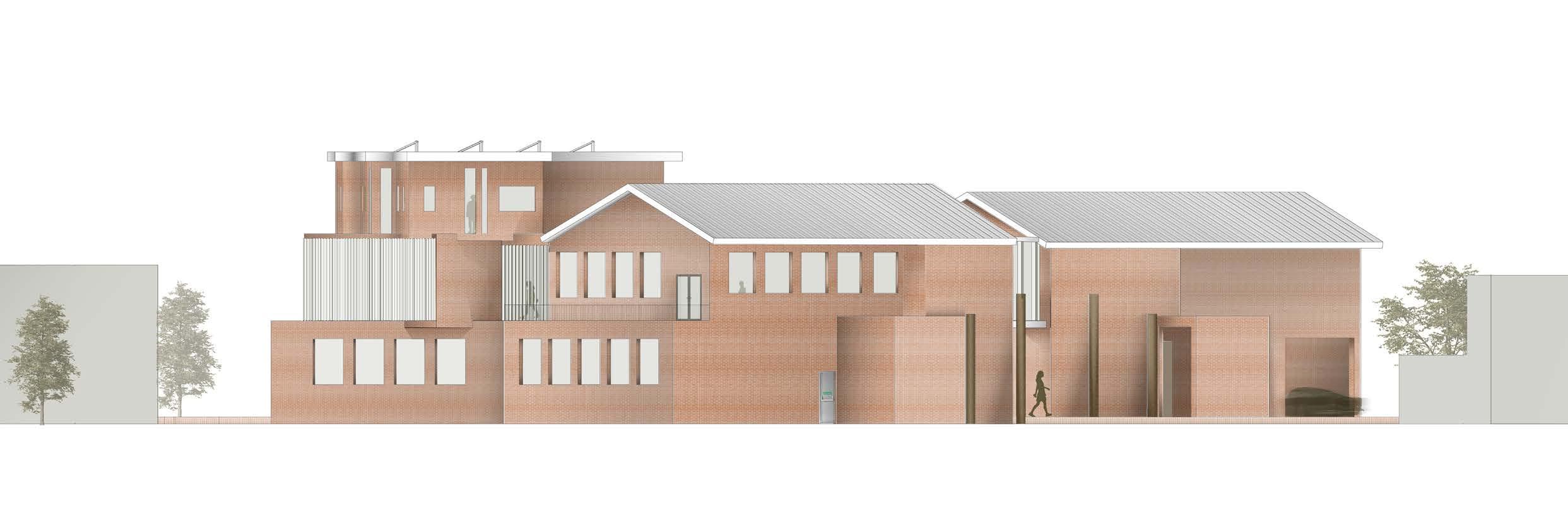
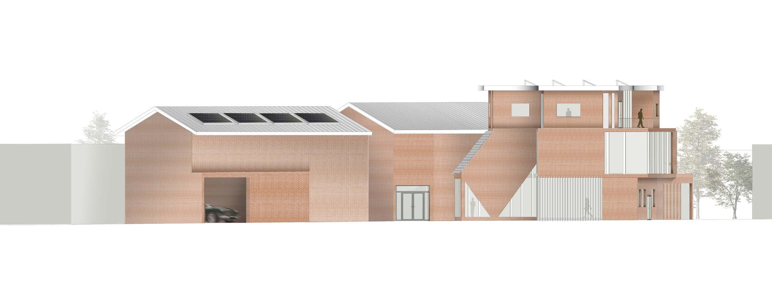
ELEVATIONS
External images
27
EAST ELEVATION
WEST ELEVATION 2m 6m 4m 1m 2m 6m 4m 1m
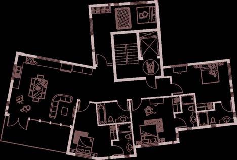
RESPONSE TO PART B :
RESPONSE TO PART K:
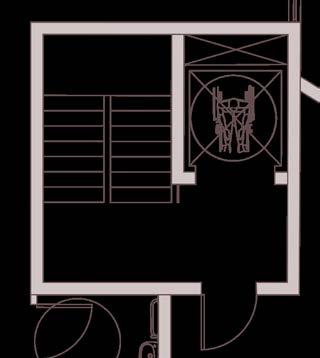
STAIR REGULATIONS:
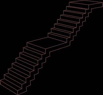
To adhere to Part K regulations, the Rise of the stairs are 170mm and the run is 250mm with 1000mm landings in between. This same measurement is used throughout the building where stairs are required including the fire safe core. The width of the stairs range between 1000mm - 1400mm
Both the ground and first floor have access to the central fireproof core & have escape routes at the entrance & exit. The industrial rooms have direct escape doors apart from the workshop room which can’t be due to the escape point leading to the canal (unsafe gathering point).
Prioritizing means of escape, these diagrams show the fire core meeting Part B dimensional regulations and show the most direct pathway from the residential rooms to the fire escape. The largest distance between a room and the escape is 8m. Sprinkler systems are installed in the kitchen area.
RESPONSE TO PART M :
Disabled facilities.:
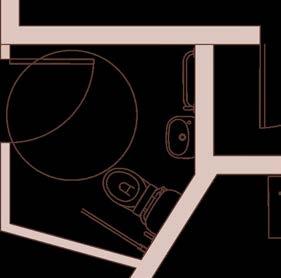
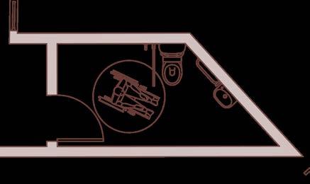
According to Part M regulations the disabled toilets must meet dimensions of 2200mm x 1500 mm
Accessible walkways:
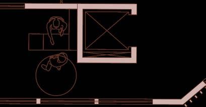
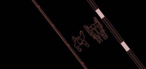
Most user walkways are between 1.7m - 2m to allowing a wheelchair and user to pass each other. The two exceptions are the entrance to the seating area and the viewing platform of the studio spaces where expansion isn’t possible (due to the canal and pitched roof).
HANDRAIL
REGULATIONS:
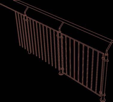
Banister height is 1000mm adhering to part K regulations with a handrail that is 40mm in diameter. When attached to wall handrail is 45mm away. When next to glazing the handrail is 200mm away to prevent people touching and spearing the glass,.
VEHICLE BARRIER: achieved via bollards in parking bays at a height of 1000mm exceeding the required height in part K.
BUILDING REGULATIONS
Intervention build up
Validating the quality and integrity of my architectural work while mitigating risks associated with non-compliance.
These references to the UK building regulations in my architectural portfolio are crucial as they demonstrate a commitment to designing safe, accessible, and sustainable spaces.
RESPONSE TO PART L :
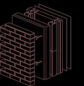
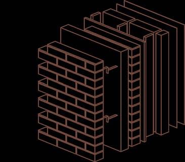
Where the building is Steel and brick clad the insulation must be 215mm of rockwool insulation to achieve a u value of 0.16W/M2K
Where the building is Brick and Brick the filler insulation is 100mm due to the existing structures limitations. An additional insulation of 100mm is placed on the interior wall with plasterboard to achieve a U value of 0.16W/M2K
The pitched roof with exposed beams where rigid insulation is 130mm over 100mm achieve a U value of 0.11W/M2K
The flat roof where rigid insulation is 110mm over 120mm achieves a U value of 0.11W/M2K
RESPONSE TO CPS:
Consideration of all CPS have been taken into account throughout the intervention. This regulation analysis page puts Emphasis on CP2 (creative users) as these regulations ensure all areas are safe and accessible to all users.
28
1550 mm 1500 mm 1000 mm 1200 mm 1500 mm 4000 mm
Steel frame, Brick clad 0.16W/M2K Brick
Brick build up 0.16 W/M2K
&
2500 mm 2000 mm 2300 mm 2000 mm 2000mm 1300 mm STAGE 7 CP4 CP1 CP5 CP3 CP2
INTERVENTION ANALYSIS
Structural and material proposal
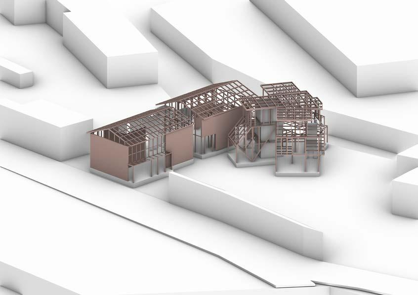
A 3d structural proposal that shows how the recycled steel frame coincides with the existing brick structure.
Embodied energy in primary materials:
- Recycled steel structure at approximately 800 kgCO₂e/tonne has around four times less embodied carbon than virgin steel. (Guide, n.d.)
- Common bricks typically have an embodied carbon of approximately 0.24 CO2/kg (Anderson, 2023). However, by using reclaimed bricks, the total building’s embodied carbon footprint is significantly reduced since the carbon within the materials remains stored rather than being released into the atmosphere .- Reusing the foundation of the existing building also reduces the carbon emissions of the project by up to 50% (Ashton, 2023).
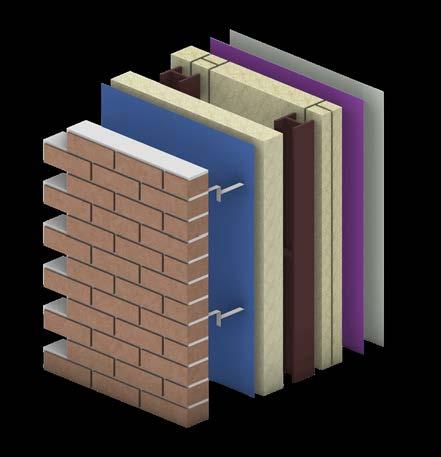
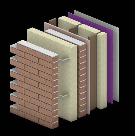
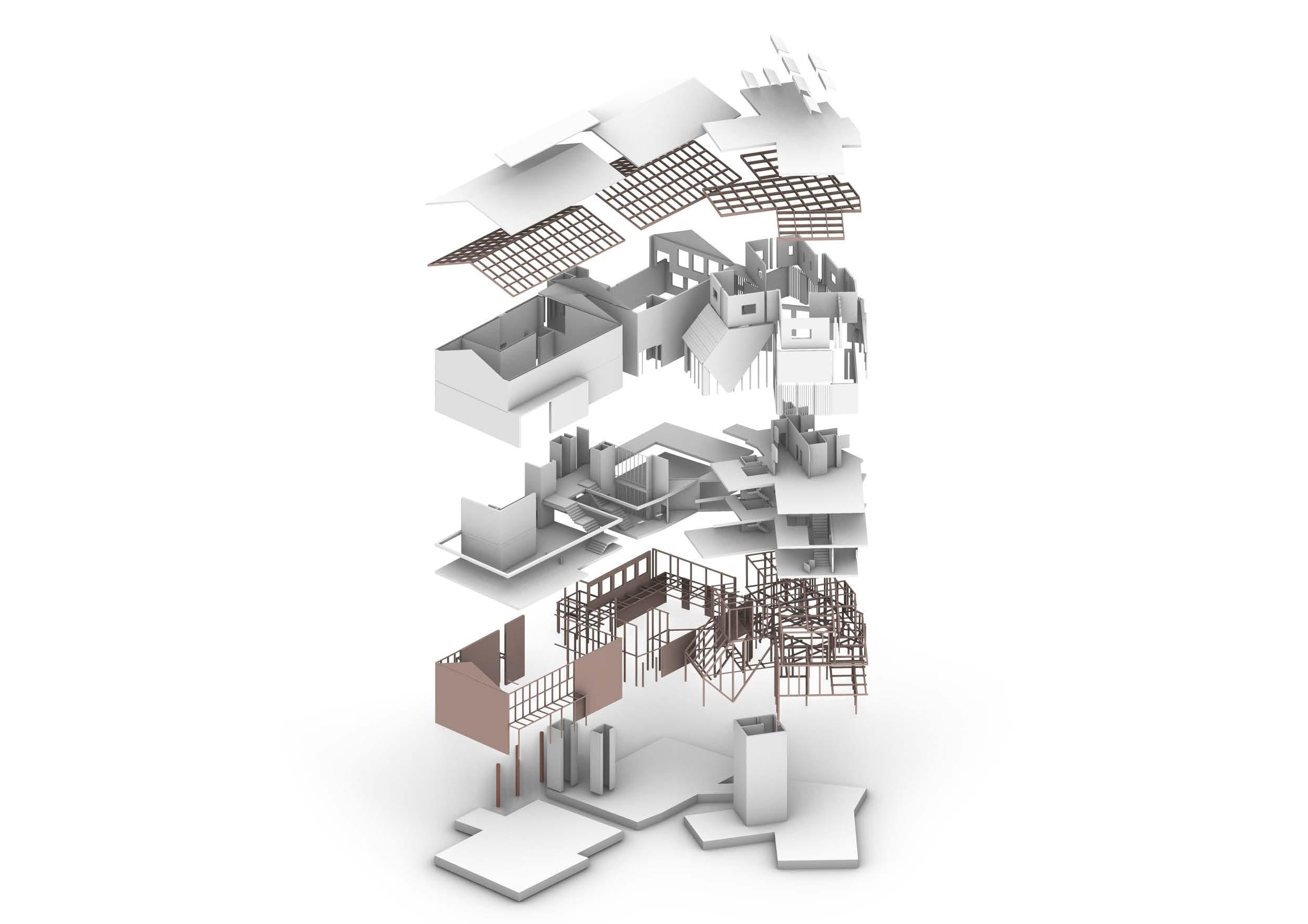
Solar panels (added after construction is completed) Pitched roof using recycled corrugated steel as cladding ( 0 embodied carbon) Flat roof Timber structured roof Steel frame, brick clad wall build up Existing brick and brick wall build up Timber intermediate floors Interior walls at a thickness of Public access staircases Steel structure Brick structure Wooden poles fixed into ground Concrete cast core using shutter form-work Poured concrete foundation
BRICK
R eclaimed brick Insulated Plasterboard Breather membrane Insulation Steel frame 100mm Insulation Vapour Control Layer W all ties Existing brick Plasterboard Insulation Existing brick Parge coat Timber battens Vapour control layer W all ties Insulation
STEEL FRAME, BRICK CLAD
& BRICK WALL BUILD UP
STAGE 7 CP4 CP1 CP5 CP3 CP2 28
STAGE 1: Destruction
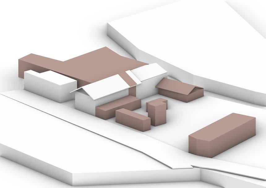
Buildings on site are demolished and material that can be re-purposed is either stored onsite or taken away to be processed and then brought back at the point of construction commencing. All other waste is disposed of responsibly.
STAGE 5: Flooring
Steel joists are connected together to construct a load-bearing floor, which is further enhanced with insulation and a poured screed on top to improve acoustic and thermal performance.
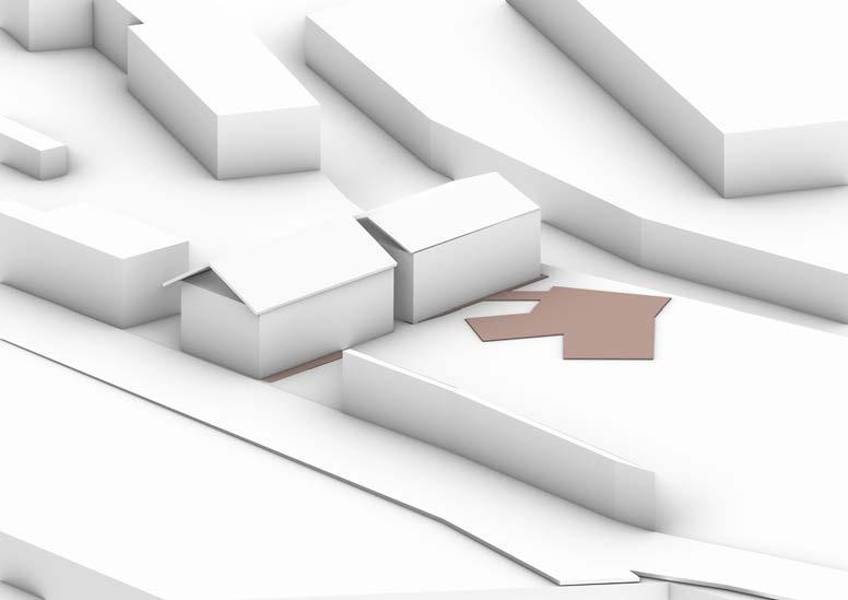
STAGE 2: Excavation
The site is levelled with appropriate machinery. The existing building is gutted and useful materials are stored for construction. Other waste is taken to appropriate recycling and waste sites.
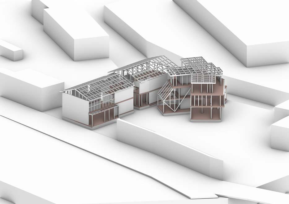
STAGE 6: Flooring
CONSTRUCTION Intervention life-cycle
Using the RIBA plan of works as a basis for the design process, the construction sequence is considered at stage 6 (manufacturing and production ). The production of information required for manufacturing and constructing should be produced at this stage.
STAGE 3: Foundation
Concrete foundation is poured and cures are concrete cast using shutter form-work. Metal poles are installed for the lift mechanism to the left of the building. The building.
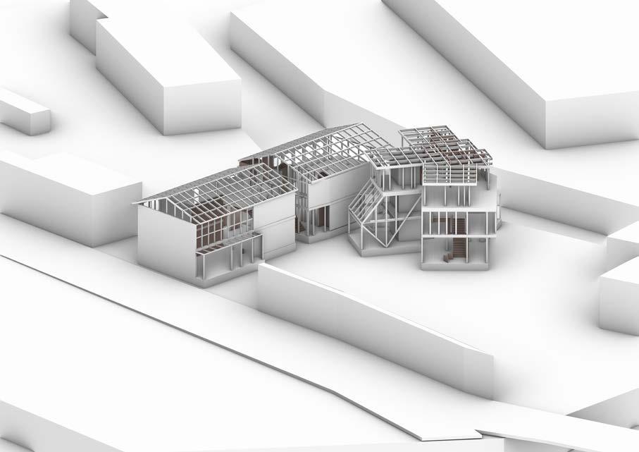
Steel joists are connected together to construct a load-bearing floor, which is further enhanced with insulation and a poured screed on top to improve acoustic and thermal performance.
Elements that the plan of work doesn’t consider are the after-end of life for the intervention life-cycle. To fully consider the material life-cycle for an intervention consideration of deconstruction is necessary. Could be considered STAGE 9 of the plan of work.
PLAN OF WORKS ‘‘STAGE 9’’
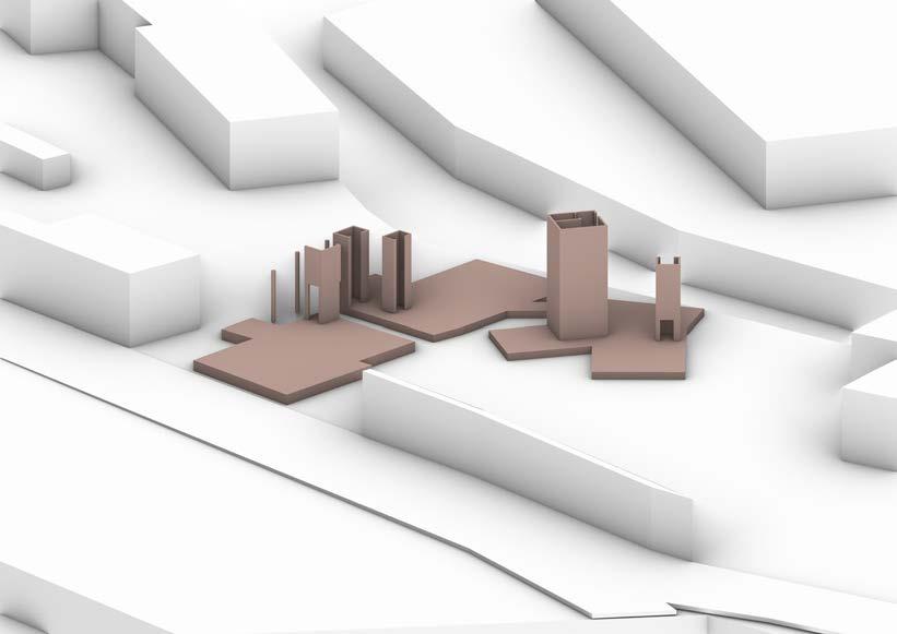
STAGE 4: Framework
Steel structure erected on site. The frames are mostly bolted for quick construction. Some joints are welded where angles are more complex. The roof framework is re-purposed from the previous building. Brick and block structure remain where applicable.
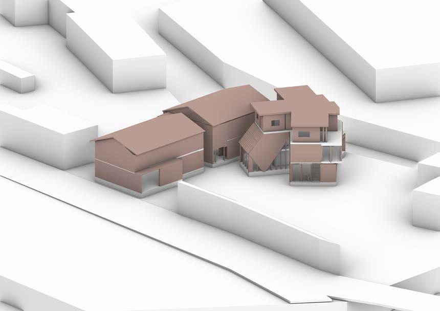
The design of my intervention creates an opportunity to de-construct the gallery space and process that material again in the first two spaces.
STAGE 7: External walls
External walls are installed with a layer of waterproofing membrane. Re-purposed window frames fitted where applicable. Both flat roof and pitched roof fitted using recycled cladding from the previous building where applicable.
STAGE 8: Finishes & landscaping
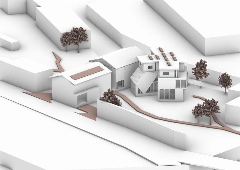
All services installed including PV panels, drainage systems, and internal heating systems. Simultaneously landscaping was completed around the intervention.
Much like the principles of my PPS the gallery space can be relocated and reconstructed elsewhere on site with the re-purposed materials freeing up its location to expand the industrial elements to cater for more material.

30
5 POINT REFLECTION
Concluding the project
Technologies Humanities
PART A&B:
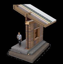
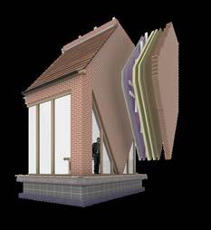
Using Lucy Carpet House (Alabama) as a case study to research the innovative technique of using recycled carpet waste to create a wall build-up. Analysing the materials, environment, Structure, and energy performance to create a better knowledge of how the building systems function.
PART C:
An in-depth testing of a north-facing fragment of my studio project. Analysing the brick construction and radiation quality of the given fragment. This has allowed me to refine my detailing in this area and I have taken my findings forward to apply elsewhere in my studio project.
Influence on studio project:
By delving into the nuances of Lucy Carpet House and dissecting the fragment of my building, I’ve successfully implemented a “material first, design second” approach in a manner that’s both justified and logical. This is exemplified through the deliberate use of recycled cladding in my intervention, showcasing a thoughtful and sustainable design ethos.
HOUSING ELECTIVE:
This lecture series discusses the definition of housing investigating broader themes such
As communities, ethics, emotions, and memory. With emphasis placed on how race, gender, and class intersect and impact housing.
These insightful discussions have led to me having a much more critical thought process in regard to residential property and how closely the sense of ‘home’ and place links directly to the individual’s identity.
The influence of biased documentation on domicide:
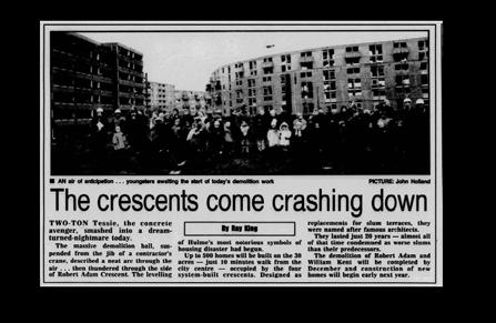
My essay discussed the implications society has on the destruction of housing using the Hulme Crescent estate as a case study.
Influence on studio project:
This elective widened my discussion of ‘after the end of life’ thinking although not directly linked too material I have discussed the significant emotional impact of the destruction of the home which strengthens the argument of why we should aim to retrofit buildings. The concept of a sense of place and home has caused me to rework my residential plans in 3.2
&rchitecture
CREATIVE COMMONS:
The goal of the ‘&’ initiative is to cultivate a commons-based approach to tackling the climate crisis, employing the ‘& Common Principles’ as a roadmap for designing a more sustainable future.
Foster a community economy by integrating with complementary interventions on the same site, envisioning an economy that fosters mutual benefit through non-monetary exchanges, drawing inspiration from ‘take back the economy.’
Our vision includes developing a program that offers both residence and spaces for production and consumption, fostering a holistic environment for sustainable living and productivity.
Influence on studio project:
The Common Principles serve as the cornerstone guiding every design decision and iteration in both 3.1 and 3.2, evident throughout the portfolios. I have considered the waste generated by other interventions on-site and explored how it can be re-purposed as an input for my intervention as well as considering the material cycle of my own intervention.
3.1 Proposition
DEBRIS TO DESIGN:
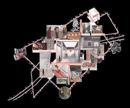
This project encompasses the initial phases of design, involving macro and micro site analysis, user analysis, concept development through a prototype performance space, brief development, and spatial coordination of my design. These stages align with the first 4 stages of the RIBA plan of works, culminating in an intermediate stage showcasing a robust concept centred around illustrating various ways society can creatively re-purpose waste.
The finishing point of this project was the concept of displaying ways to process waste to educate and teach users and the public.
Influence on studio project:
Site research and the development of the P.P.S. in 3.1 have heavily influenced my materiality and program in 3.2. A meticulous analysis of my plan iterations towards the end of section 3.1, considering building regulations, has led to substantial iteration changes in my intervention. These changes are crucial to ensuring the building functions effectively and maintains safety standards.
3.2 Development
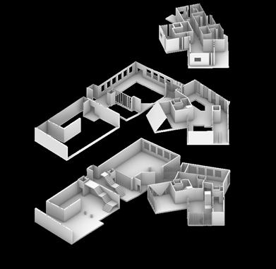
A DEMONSTRATION OF MATERIAL POTENTIAL AFTER END OF LIFE:
Developing from the finishing point of 3.1 this project has continued to evolve into an intervention that responds to the Common principles, RIBA sustainable outcomes & the climate crisis.
Further development:
- A further consideration of what sculptures would be produced in the intervention and how they would lead a user on site to the intervention.
- Simulations at part 8 of RIBA plan of works to determine any areas of weakness before construction.
What next?
Consider the technologies and methods needed to dismantle the interventions gallery section while preserving the other two spaces intact. The goal is to reconstruct the gallery elsewhere on-site and redesign the existing spaces to function exclusively as production areas. This process should involve adapting the gallery’s materiality to fit its new environment while maintaining a re-purposed material aesthetic.
31
REFERENCES
Anderson, J. (2023). Embodied Carbon (aka Embodied Energy) & EPDs. [online] www.greenspec.co.uk. Available at: https://www. greenspec.co.uk/building-design/embodied-energy/.
Ashton, D. (2023). What is embodied carbon (and what can we do about it)? [online] University College of Estate Management. Available at: https://www.ucem.ac.uk/whats-happening/articles/ what-is-embodied-carbon/#:~:text=Renovating%2C%20retrofitting%20and%20reusing%20buildings [Accessed 17 May 2024].
Guide, N.Z.C. (n.d.). Embodied Carbon Strategies. [online] Net Zero Carbon Guide. Available at: https://www.netzerocarbonguide.co.uk/guide/designing-and-building/materials-strategy/embodied-carbon-strategies.
FIGURES:
Figure 1: Benjy Hansen-Bundy (2018) A Week Inside WeLive, the Utopian Apartment Complex That Wants to Disrupt City Living, GQ. GQ. Available at: https://www.gq.com/story/inside-welive.
Figure 2: Benjy Hansen-Bundy (2018) A Week Inside WeLive, the Utopian Apartment Complex That Wants to Disrupt City Living, GQ. GQ. Available at: https://www.gq.com/story/inside-welive.
Figure 3: Adelyn Perez (2010) AD Classics: AD Classics: Centre Georges Pompidou / Renzo Piano Building Workshop + Richard Rogers, ArchDaily. Available at: https://www.archdaily. com/64028/ad-classics-centre-georges-pompidou-renzo-piano-richard-rogers.
Figure 4: Adelyn Perez (2010) AD Classics: AD Classics: Centre Georges Pompidou / Renzo Piano Building Workshop + Richard Rogers, ArchDaily. Available at: https://www.archdaily. com/64028/ad-classics-centre-georges-pompidou-renzo-piano-richard-rogers.
Figure 5: Adelyn Perez (2010) AD Classics: AD Classics: Centre Georges Pompidou / Renzo Piano Building Workshop + Richard Rogers, ArchDaily. Available at: https://www.archdaily. com/64028/ad-classics-centre-georges-pompidou-renzo-piano-richard-rogers.
31
