SERVICE MANUAL
Foreword
The Operator's Manual
You and others can be killed or seriously injured if you operate or maintain the machine without first studying the Operator's Manual. You must understand and follow the instructions in the Operator's Manual. If you do not understand anything, ask your employer or JCB dealer to explain it.
Do not operate the machine without an Operator's Manual, or if there is anything on the machine you do not understand.
Treat the Operator's Manual as part of the machine. Keep it clean and in good condition. Replace the Operator's Manual immediately if it is lost, damaged or becomes unreadable.
Operation
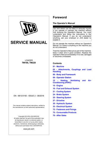
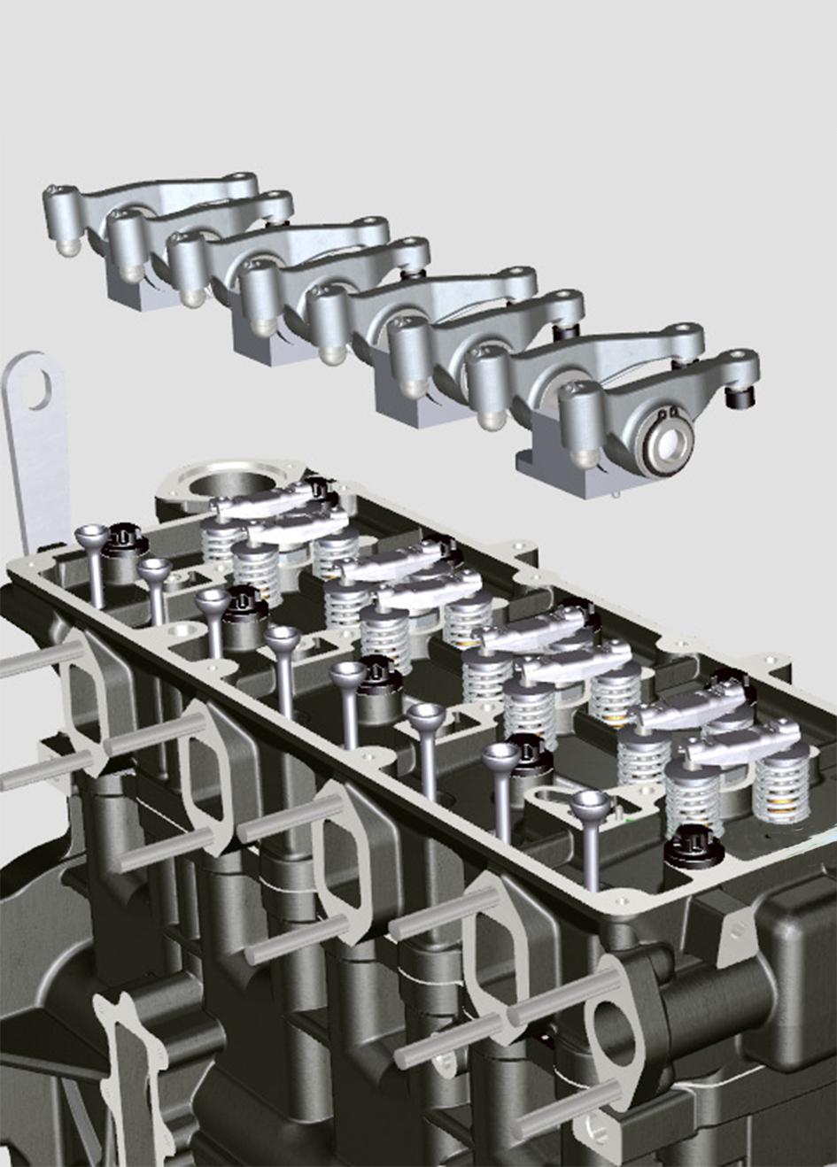
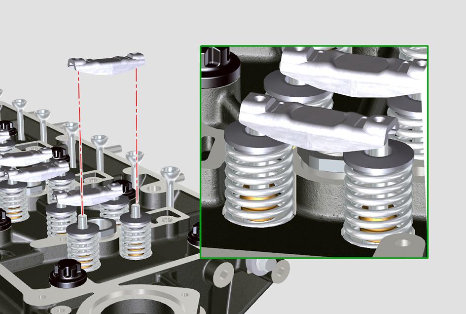
When the camshaft lobe raises the push-rod, the push-rod pushes the rocker arm up. Due to this the rocker arm presses down on the valve stem to open the valve. When the rocker arm returns due to the camshafts rotation, the valve spring closes the valve.

Lubrication
Oil is fed from the main gallery through a drilling which passes up through the crankcase and cylinder
head to a small transfer gallery under the rocker shaft pedestal. The oversize rocker shaft fixing bolt hole allows oil to pass into a drilling in the centre of the rocker shaft. Further cross drillings transfer oil to each of the rocker pivot bushes. A cross drilling in each rocker transfers oil to the top of the rocker where it flows by gravity along a groove to the rocker tip.
Check (Condition)
1.Check the rocker shaft and rocker bushings for signs of damage and excessive wear. Measure the rocker shaft diameter and rocker bearing bushes to confirm they are within service limits. Refer to Technical Data. Note: The rocker bearing bushes are not renewable. If a rocker bearing bush is damaged or worn the rocker must be renewed as a complete assembly.
Refer to: PIL 15-42.
2.Make sure that all oil-ways and cross drillings in the rocker shaft, rocker arms and pedestals are clear and free from debris. Use an air line to blow through cross drillings.
Remove and Install
Before Removal
1.Make sure that the engine is safe to work on. If the engine has been running, let it cool before you start the service work.
2.Get access to the engine.
3.Disconnect and remove the fuel pipes from the fuel injectors.
Refer to: PIL 18-96.
4.Remove the rocker cover. Refer to: PIL 15-42-06.
Remove
1.Remove the rocker shaft fixing screws.
A Rocker shaft fixing screw (x4)
B Rocker arm assembly
C Cylinder head
2.Make sure that you keep all the fixing screws in their original positions.
3.Lift the rocker arm assembly from the cylinder head completely.
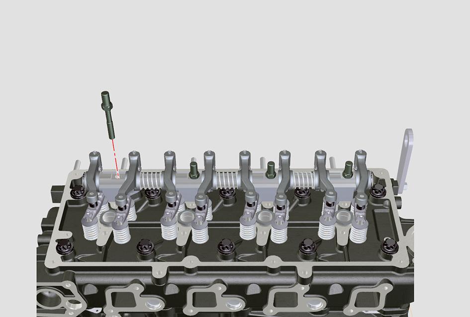
4.Lift off the valve bridge pieces from the pairs of inlet and exhaust valves.
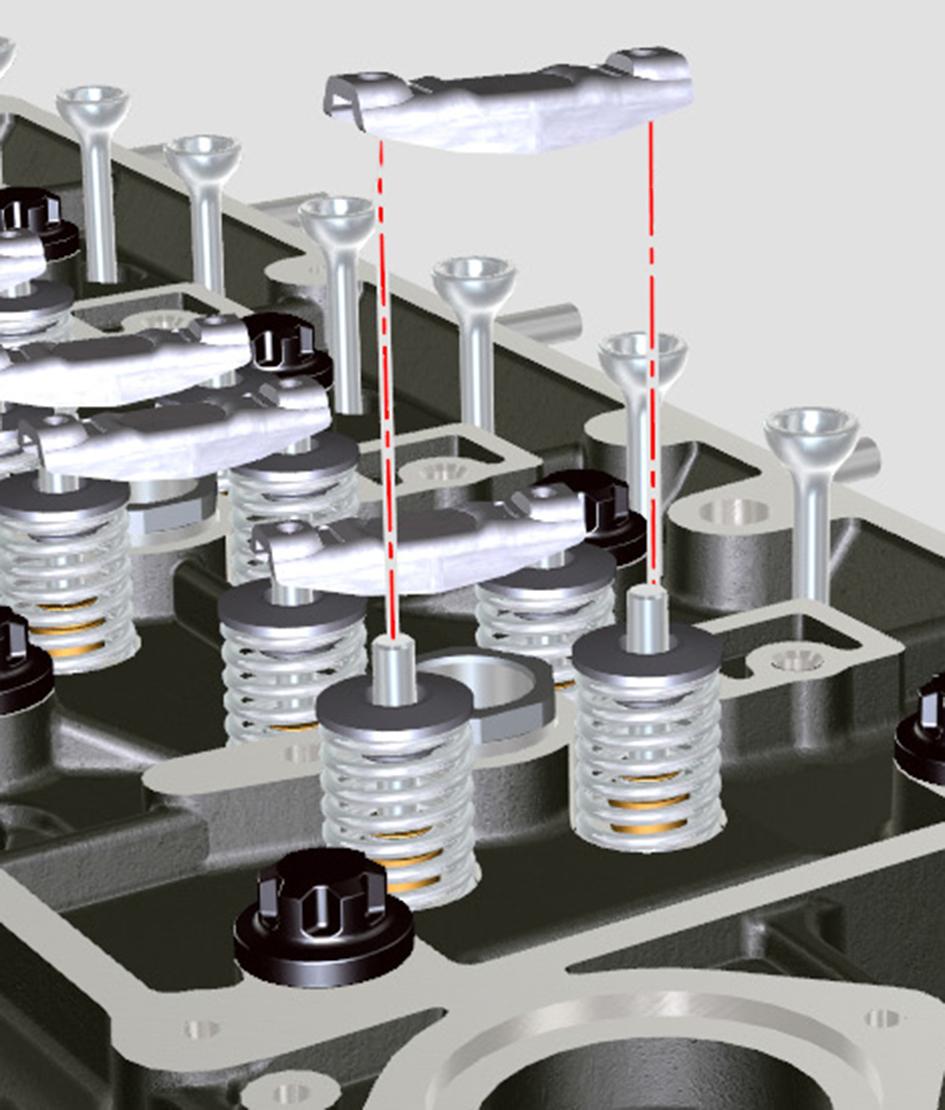
5.Remove the push rods from the crankcase.
Before Installation
1.Make sure that all items are clean and free from damage and corrosion. If components within the rocker assembly are damaged or worn.
2.Make sure that all oilways and cross drillings in the cylinder head, rocker shaft and pedestals are clear and free from debris. Use an air line to blow through the cross drillings.
3.Use a suitable degreasing agent to clean the top of the cylinder head.
Install
1.The installation procedure is the opposite of the removal procedure. Additionally do the following steps.
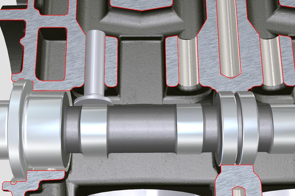
2.Insert the push rods into the crankcase. Make sure that they engage with the camshaft tappets. Figure 233.
3.Install the bridge pieces on to the pairs of inlet and exhaust valves in the cylinder head.
4.Align the rocker arm assembly on a level surface.
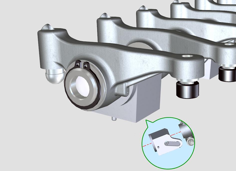
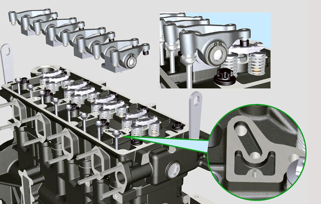
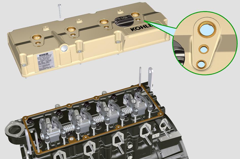
5.Make sure that you install the rocker arm assemblyonthecylinderheadwithrespecttothe plug and the holder.
6.Make sure that the rocker arm assembly is seated properly on the push rod.
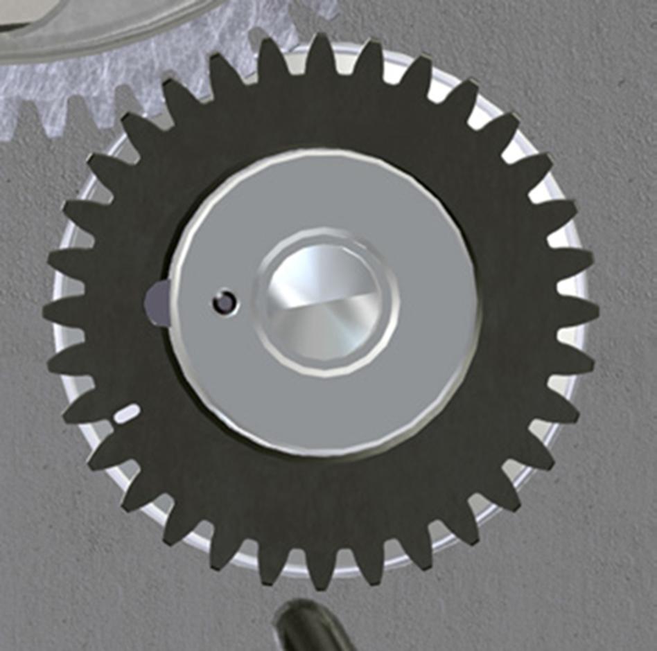
7.Make sure that you put the crankshaft gear key in the position as shown to avoid the rocker arm rod bending at the time of tightening the fixing screws.
8.Put the rocker arm fixing screws and tighten the screws in the sequence shown.
9.Tighten the screws to the correct torque value.
After Installation
1.Measure and adjust the valve clearances. Refer to: PIL 15-30.
2.Install the rocker cover. Refer to: PIL 15-42-06.
3.Install and connect the fuel pipes to the fuel injectors.
Refer to: PIL 18-96.
Table 76. Torque Values
Disassemble and Assemble
Before Disassembly
1.Remove the rocker cover. Refer to: PIL 15-42-06.
2.Remove the rocker assembly. Refer to: PIL 15-42-00.
Disassemble
1.Remove the retainer ring.
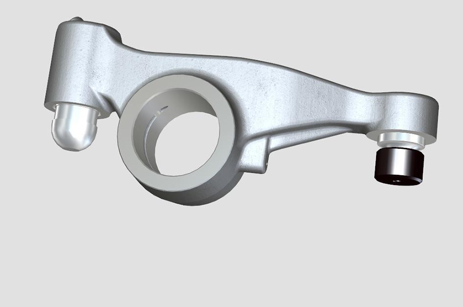
A Discharge rocker arm
B Hydraulic tappet
C Retainer
D Shoulder ring
2.Remove the shoulder ring.
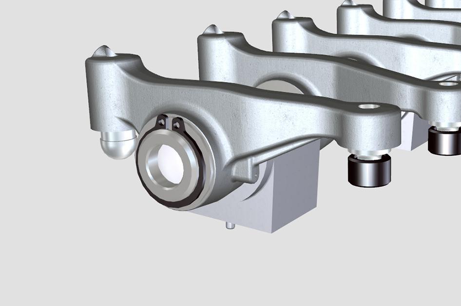
3.Remove the rockers and the holders from the rocker shaft.
A Discharge rocker arm
E Rocker shaft
F Holder
G Holder 1
4.Label the rockers and the holders to make sure that they are installed in the correct positions on assembly.
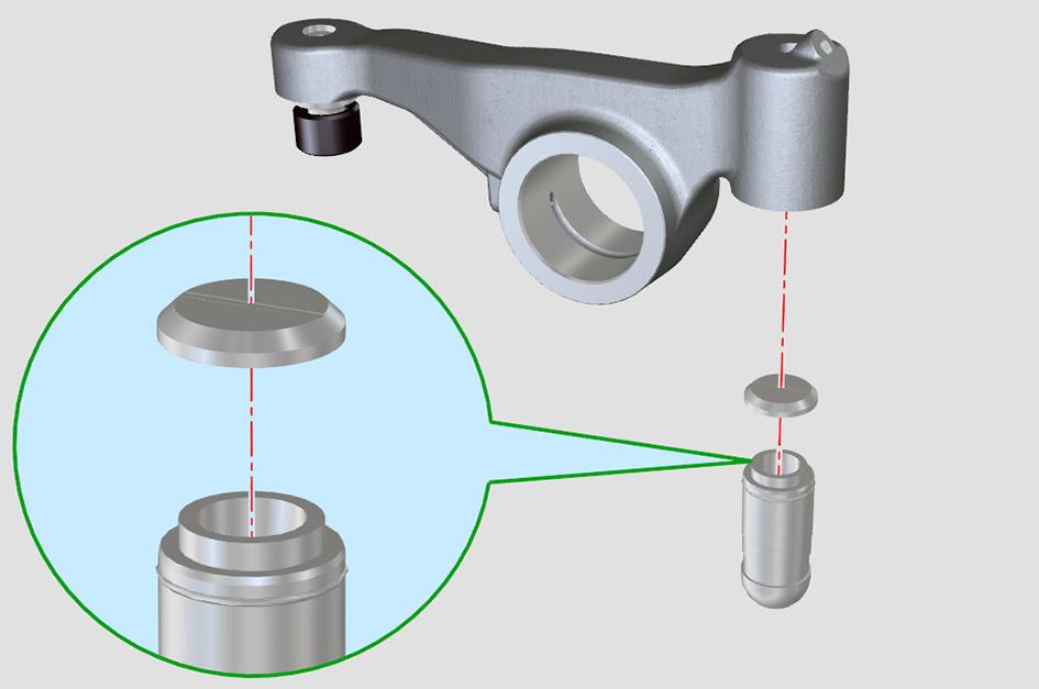
5.Remove the tappets from the rocker.
A Discharge rocker arm
B Hydraulic tappet
H Chamber
J Pad
2.4.Position the rocker arm in the pliers.
2.5.Use the pliers to push the tappet through the rocker arm until the tappet is properly inserted.
3.Lubricate the rocker shaft with clean engine oil.
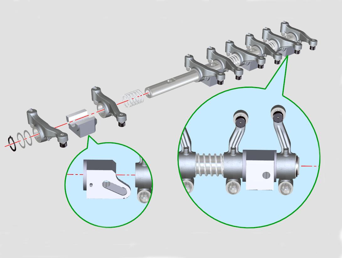
4.Installtherockerarmsinthecorrectposition,turn the rocker shaft with the lower height towards the timing gear system side.
5.Put the lock ring into the seat of the rocker shaft.
Figure 243.
A Discharge rocker arm
B Hydraulic tappet
6.Check (Condition) of the rocker arm assembly for signs of damage and excessive wear. Refer to: PIL 15-42-00.
Assemble
1.The assembly procedure is the opposite of the disassembly procedure. Additionally do the following steps.
2.Install the tappets into the rocker arm.
2.1.Insert the tappets into the hydraulic tappet insertion pliers.
Special Tool: Insertion Pliers for Hydraulic Tappets (Qty.: 1)
2.2.Fill the chamber of the tappet with oil.
2.3.Put the pad on the tappet.
C Retainer
D Shoulder ring
E Rocker shaft
K Seat
L Rocker shaft lower height
6.Position the fixing screw support surface facing upwards.
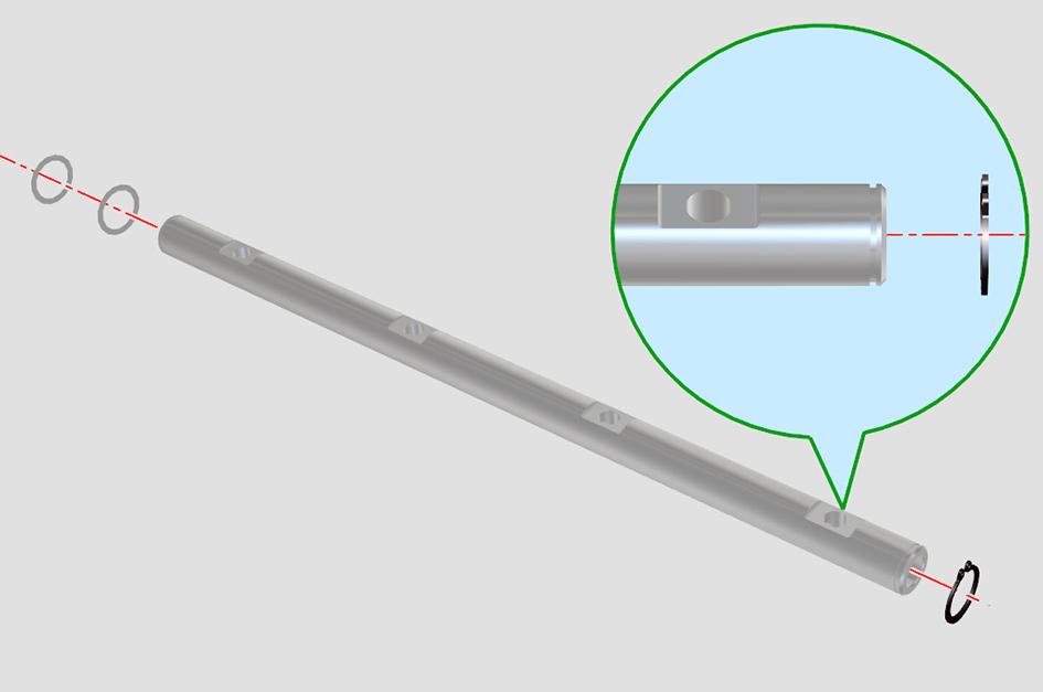
7.Put the two shoulder rings on the rocker shaft.
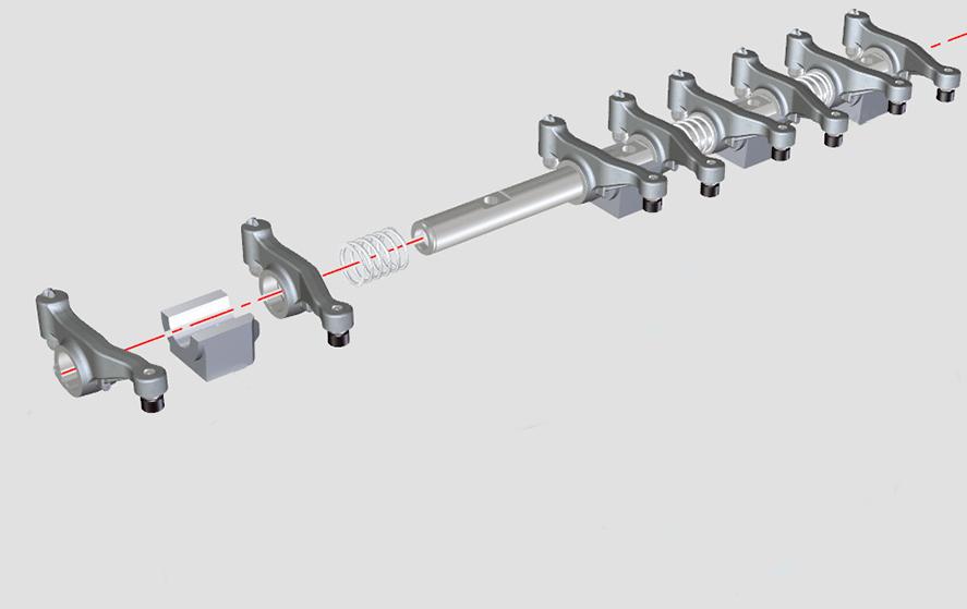
8.Sequentially put the suction rocker arm, the holder and the discharge rocker arm on the rocker shaft.
A Discharge rocker arm
C Retainer
D Shoulder ring
E Rocker shaft
F Holder
G Holder 1
M Spring
N Suction rocker arm
9.The discharge rocker arm is shorter than the suction rocker arm.
10.Install the spring on the rocker shaft.
11.Do the steps 8 and 10 for all the remaining rocker arms.
12.Install the holder 1 with the last pair of rocker arm towards the flywheel.
13.The spring makes sure that the holder and the holder 1 are kept in place.
14.Make sure that the rockers are installed in their original positions along the rocker shaft.
15.Put the shoulder rings and the lock ring to lock all the components on the rocker shaft.
After Assembly
1.Install the rocker assembly. Refer to: PIL 15-42-00.
2.Install the rocker cover. Refer to: PIL 15-42-06.
1.Make sure that the engine is safe to work on. If the engine has been running, let it cool before you start the service work.
2.Clean the engine.
Refer to: PIL 15-00-00.
8.Lift the rocker cover from the cylinder head
9.Discard the gasket.
10.Therockercoverinjectorsealsmustbereplaced. Refer to: PIL 18-18-03.
Install
1.Remove all oil and sludge contamination from inside the valve chamber.
2.Use a new rocker arm cover gasket.
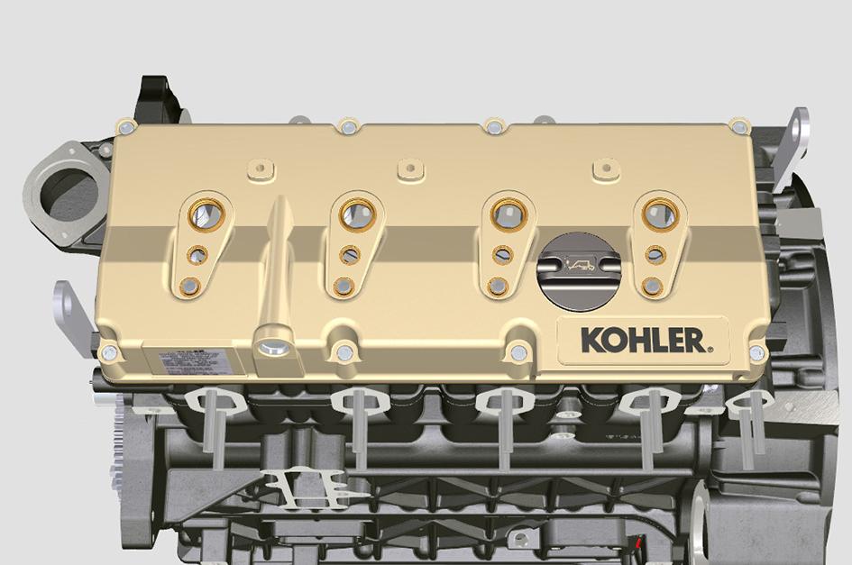
A Rocker arm cover B Screws C Gasket
Remove
1.Get access to the engine.
2.Remove the high pressure fuel pipes.
Refer to: PIL 18-96-03.
3.Remove the fuel bleed off fuel pipes.
Refer to: PIL 18-96-06.
4.Disconnect the electrical connectors at the fuel injectors.
Refer to: PIL 18-18-03.
5.Disconnecttheelectricalconnectoratthecoolant temperature sensor.
Refer to: PIL 15-84-33.
6.Move the electrical harness away from the rocker cover.
7.Progressively remove the rocker arm cover screws from 1 to 8 in reverse order, starting at bolt 8.
3.Make sure you align the gasket on the cylinder head with the rocker cover fastening screws.
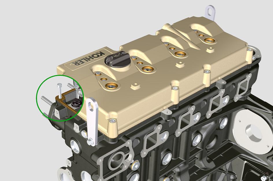
4.Locate the two guide pins before mounting the rocker arm cover.
Special Tool: Rocker Arm Cover Mounting Studs (Qty.: 1)
5.Put sleeves/covers on the four injectors to prevent from damage.
6.Apply a Vaseline lubricant to the seals.
A Rocker arm cover
B Screws
C Gasket
D Guide pins
E Seal (lubricate upper part)
F Seal (lubricate inner part)
7.Install the rocker arm cover and put the screws in sequence from 1 to 8.
8.Tighten the screws to the correct torque value.
9.Remove the sleeves/covers.
After Installation
1.The high pressure fuel pipes must be replaced with new parts.
Refer to: PIL 18-96-03.
2.Start the engine and check for oil and fuel leaks.
Item Nm B 10
(1) Measure the diameter at two points. The difference between the two values measured must not be more than be 0.02mm.
42 - Rocker and Fittings
21 - Tappet
Component Identification
A Low pressure chamber
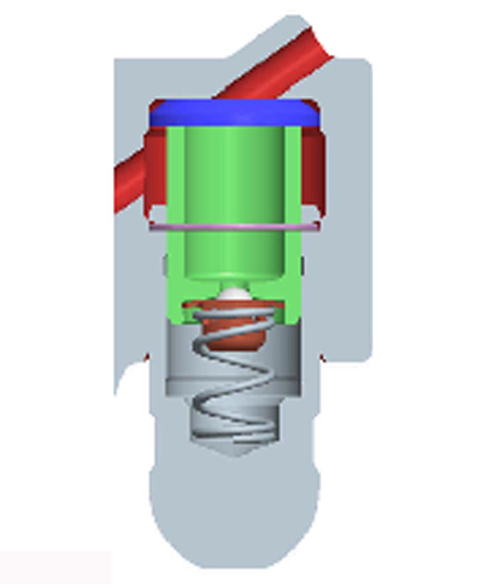
C Hydraulic tappets oil refill pipe
E Piston
G Tappet body
B High pressure chamber
D Retaining ring
F Unidirectional valve
H Spring
Operation
Hydraulic Tappet
The operating principle of the hydraulic tappet is based on the incompressibility of the liquid and on controlled leakage between the piston and the tappet body.
A constant supply of pressurised oil is provided to the low pressure chamber. The pressurized oil can only get the access to the high pressure chamber through the unidirectional (non-return) valve.
The high pressure chamber is filled when the rocker arm is on the base radius of the cam and the spring holds the piston against the valve stem preventing from system play as well as vibration and noise.
Due to the spring movement, the tappet extends. This creates a small pressure decrease in the high pressure chamber to open the non-return valve. Oil is then transferred from the low pressure chamber to the high pressure chamber to restore the proper amount of oil required to eliminate any play in the valves.
Difficult Operating Conditions
For proper operation of the hydraulic tappets it is essential that the low pressure chamber of the piston is always full of oil.
In some conditions this may not occur (due to the fact that oil leaks away when the engine is switched off, which can also partially drain the tappets): this situation will result in play that will occur with a typical noise similar to ticking, not to be confused with the normal ticking of the injectors.
When the engine is cold, the tappet filling time could be very long if the oil used is not suitable for the specific environmental conditions.
If the engine is very hot or at idle speed, oil pressure may be low, and small air bubbles could form in the circuit. Because of this, the lubricant becomes compressible, thus compressing the tappet slightly and producing valve play which is responsible for the ticking sound.
In all cases, the ticking should not last too long (max 5 minutes) if not, the problem will surely be due to the poor quality of the oil, wear or impurities that, transported by the oil, can infiltrate between the ball valve and its seat inside the piston This affects the operationofthetappetitself.Inthesecasesyoumust replace the oil or the hydraulic tappets.
Continuous ticking or abnormal sound for prolonged periods is a symptom of a possible malfunction, and
requires the removal and replacement of oil and hydraulic tappets.
Check (Condition)
Tappets and Tappet Housing Check
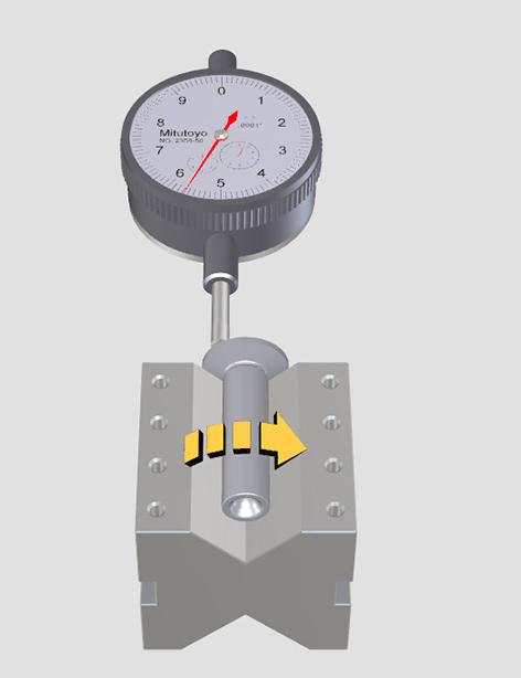
1.Put the tappet on a V-notch surface plate.
2.Measure the following dimensions of the tappet and tappet housing.
2.1.Perpendicularity of the base with a dial gauge.
2.2.Length of the tappet to assess the wear.
2.3.Diameter of the tappet housing with an internal dial gauge.
3.Make sure that you measure the housing diameter at two locations and the difference between the two values should not be more than 0.02mm.
4.Measure the clearance between the tappet and the tappet housing from the values derived in step 2.
5.Make sure that all the values are within the allowable limits.
Refer to: PIL 15-42-21.
Calibrate Tappets Dimensions
Use a surface plate and a dial gauge as shown. Check the perpendicularity of the plate, making the tappet rotate in the direction of the arrow. With a gauge, check the length of the tappet to assess wear. The values measured must be within tolerances. Refer to: PIL 15-42-21.
Clearance between Tappet and Housing
Use an internal dial gauge to measure the diameter of the tappet housings. Measure quota in two different points. The difference between the two values measured must be within tolerance. Refer to: PIL 15-42-21.
00 - General
Technical Data
Remove and Install Oil
Oil is toxic. If you swallow any oil, do not induce vomiting, seek medical advice. Used engine oil contains harmful contaminants which can cause skin cancer. Do not handle used engine oil more than necessary. Always use barrier cream or wear gloves to prevent skin contact. Wash skin contaminated with oilthoroughlyinwarmsoapywater.Donotusepetrol, diesel fuel or paraffin to clean your skin.
CAUTION! It is illegal to pollute drains, sewers or the ground. Clean up all spilt fluids and/or lubricants. Used fluids and/or lubricants, filters and contaminated materials must be disposed of in accordance with local regulations. Use authorised waste disposal sites.
CAUTION! Oil will gush from the hole when the drain plug is removed. Keep to one side when you remove the plug.
Before Removal
1.Get access to the engine.
2.Drain the engine oil. Refer to: PIL 15-00-00.
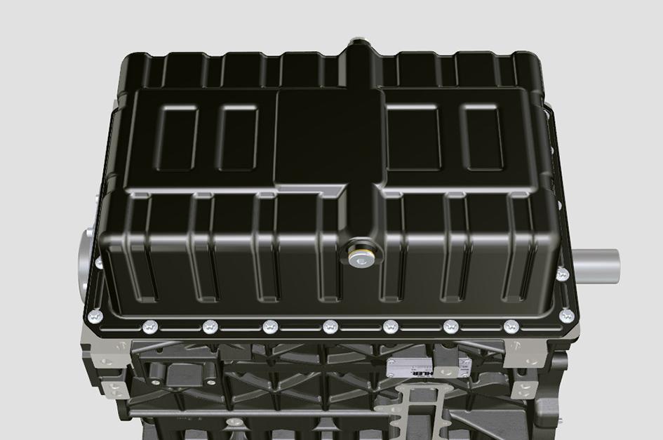
Remove
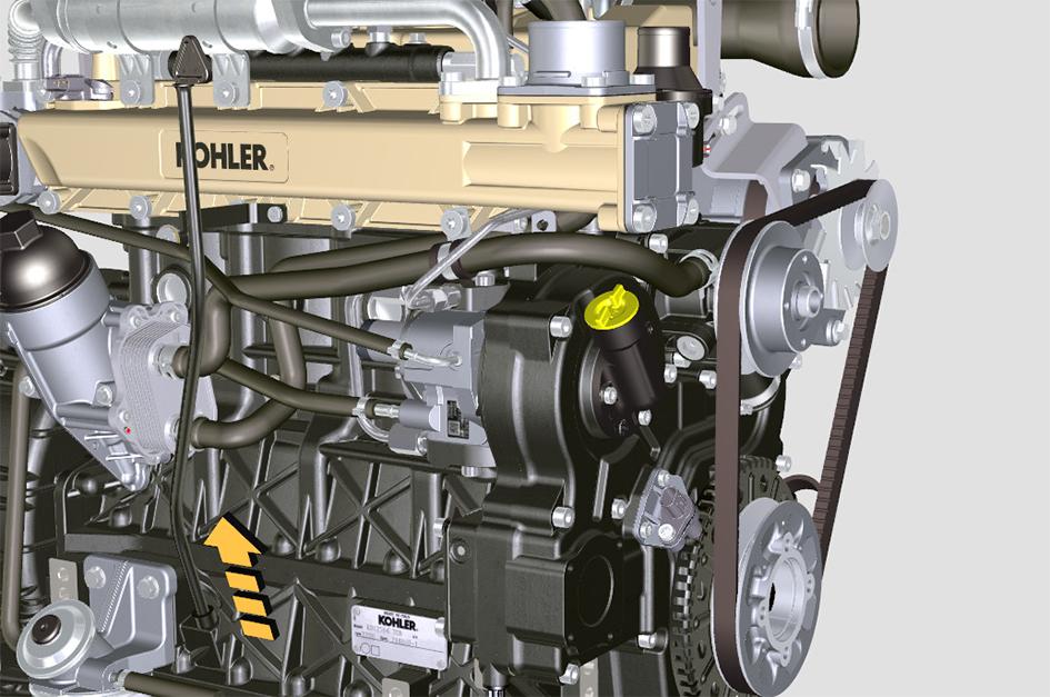
1.Remove the screws that attach the oil sump to the bedplate.
2.Insert plates in the areas shown by the arrows.
Figure 254.
3.Lift the plates to remove the oil sump.
4.Remove the remaining sealant from the oil sump and bedplate contact surfaces.
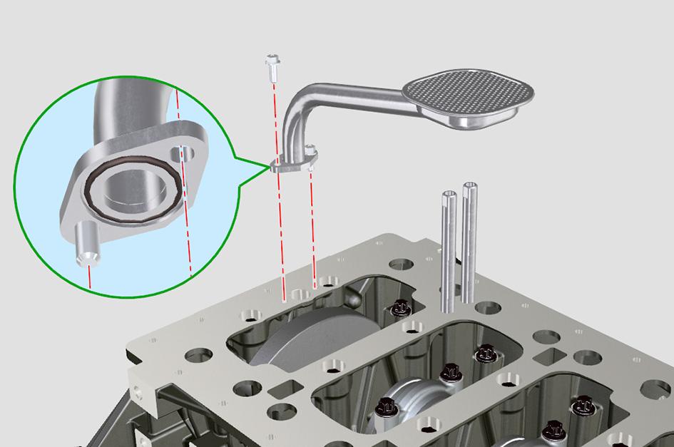
5.Remove the screws that attach the oil intake pipe.
6.Remove the oil intake pipe and the gasket. Discard the gasket.
8.Apply a bead of sealant (Loctite 5660) on the oil sump contact surface to the specified thickness.
Dimension: 2.5mm
Figure 257.
F Screw
G Oil intake pipe
H Gasket
7.Remove the oil vapour pipes.
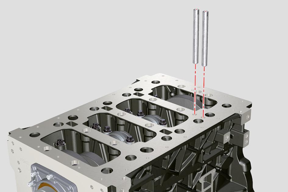
K Mounting studs
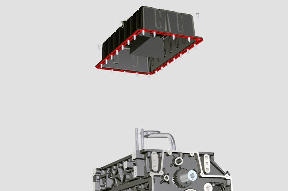
L Screw
M Sealant application surface
9.Install the mounting studs to help you to position the oil sump.
10.Put the oil sump on the bedplate. Make sure that the screw holes are aligned.
11.Strictly follow the torque tightening sequence. Tighten the screws to the correct torque value.
Install
1.Apply Loctite 648 on the threads of the oil vapour pipes.
2.Install the oil vapour pipes.
3.Put a new gasket in the seat of the oil intake pipe.
4.Attach the oil intake pipe onto the bedplate with the screws.
5.Tighten the screws to the correct torque value.
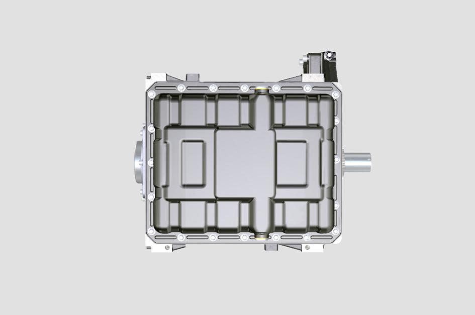
6.Makesurethattheoilsumpiscleanandfreefrom contamination.
7.Make sure that the contact faces on the oil sump and bedplate are clean.
12.After you tighten all of the screws, loosen screw no.1 and tighten again to the correct torque value.
13.Clean and install the drain plugs with a new Oring. Tighten the plug to the correct torque value.
14.Throughoneofthefillerpoints,filltheenginewith the recommended oil to the MAX mark on the dipstick.
15.Wipe off any spilt oil, install the filler cap and make sure it is secure.
16.Operate the engine, until the oil pressure low warning light has extinguished.
17.Check for oil leakage.
18.When the oil has cooled, check the oil level again, and if necessary top up with clean engine oil.
Item Nm
B 35 F 10 L 25
03 - Drain Plug
Remove and Install
Oil
Oil is toxic. If you swallow any oil, do not induce vomiting, seek medical advice. Used engine oil contains harmful contaminants which can cause skin cancer. Do not handle used engine oil more than necessary. Always use barrier cream or wear gloves to prevent skin contact. Wash skin contaminated with oilthoroughlyinwarmsoapywater.Donotusepetrol, diesel fuel or paraffin to clean your skin.
CAUTION! It is illegal to pollute drains, sewers or the ground. Clean up all spilt fluids and/or lubricants. Used fluids and/or lubricants, filters and contaminated materials must be disposed of in accordance with local regulations. Use authorised waste disposal sites.
Remove
Drain the oil when the engine is warm as contaminants held in suspension will then be drained with the oil.
1.Gain access to the oil sump.
2.Place a container of suitable size below the drain plug.
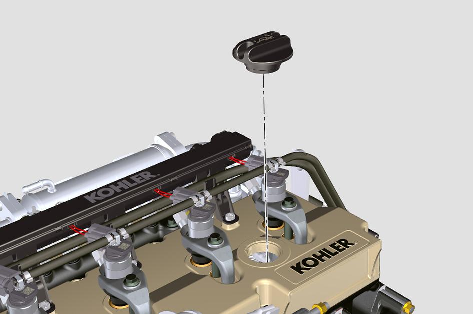
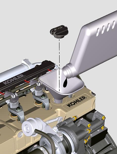
3.Remove the oil filler cap.
A Oil filler cap
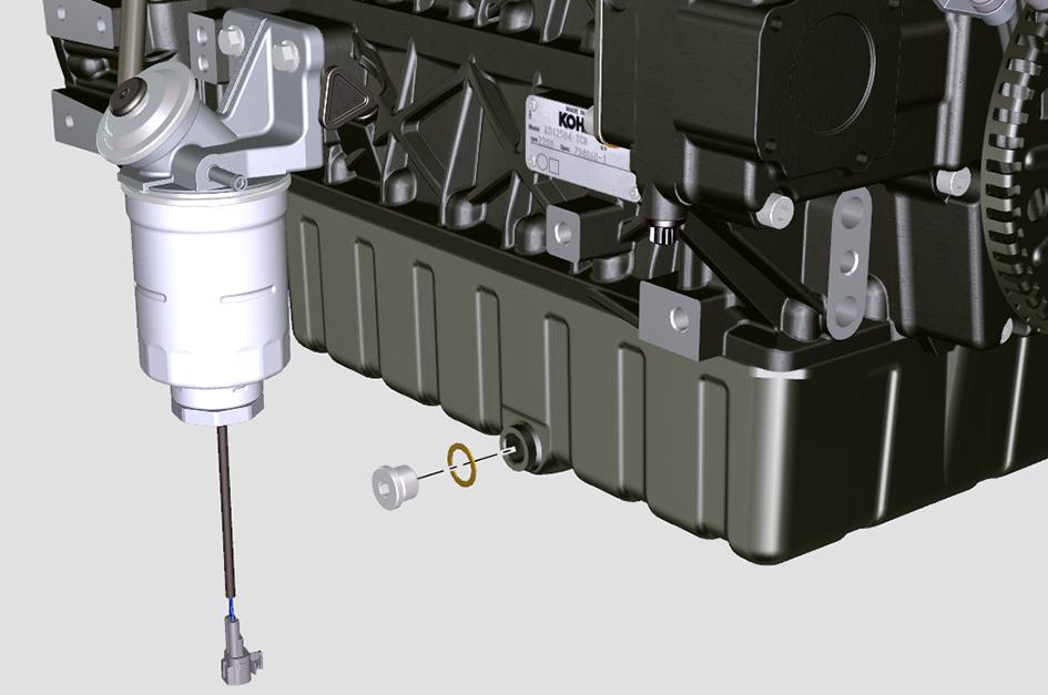
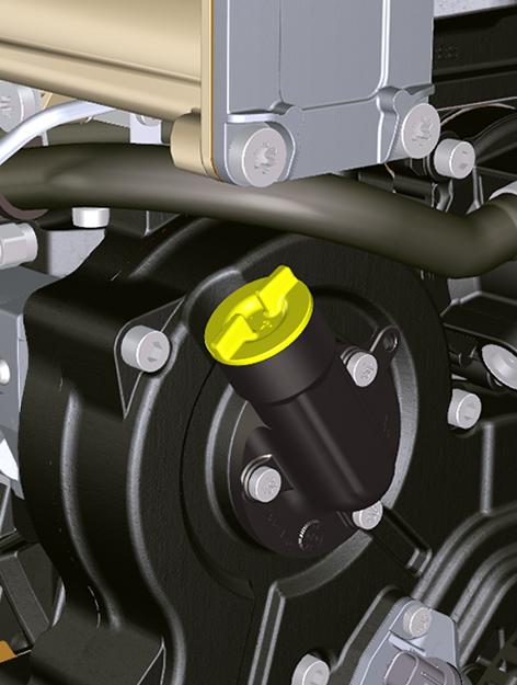
CAUTION! Oil will gush from the hole when the drain plug is removed. Keep to one side when you remove the plug.
4.Remove the oil sump drain plug and O-ring. Let the oil drain out.
B Drain plug C O-ring
Install
1.CleanandinstallthedrainplugwithanewO-ring.
2.Tighten the plug to the correct torque value.
3.Throughoneofthefillerpoints,filltheenginewith the recommended oil to the MAX mark on the dipstick.
4.Wipe off any spilt oil, install the filler cap and make sure it is secure.
5.Operate the engine, until the oil pressure low warning light has extinguished.
6.Check for oil leakage.
7.When the oil has cooled, check the oil level again, and if necessary top up with clean engine oil.
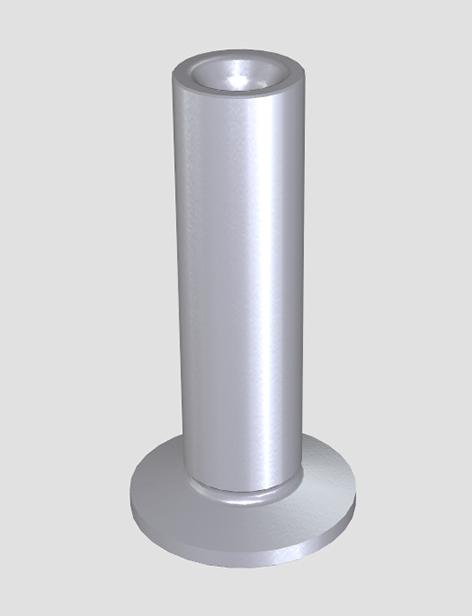
09 - Dipstick
Check (Level)
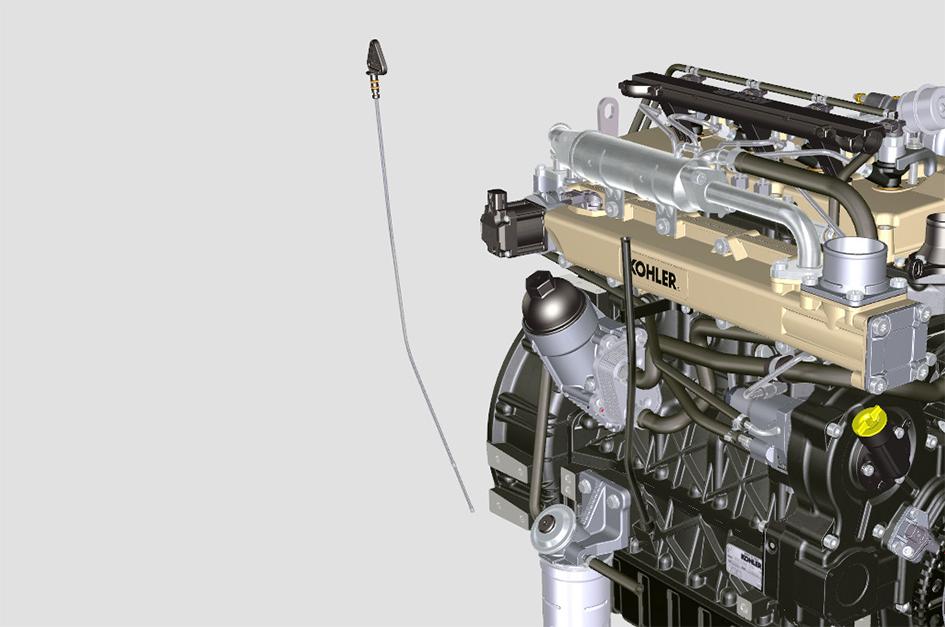
1.Remove the engine oil dipstick.
2.Make sure that the oil level is at the MAX mark on the dipstick.
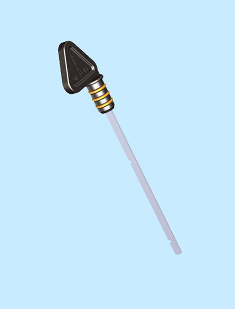
3.If the oil level is below the required quantity, fill the engine with the recommended oil through the oil filler point.
D Dipstick
E Maximum level mark
F Minimum level mark
45 - Oil Sump
10 - Dipstick Pipe
10 - Dipstick Pipe
Remove and Install
Before removal
1.Make sure that the engine is safe to work on. If the engine has been running, let it cool before you start the service work.
2.Get access to the engine.
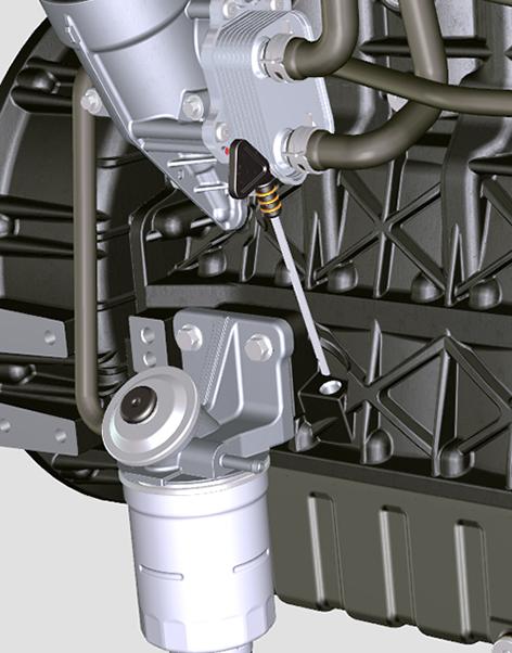
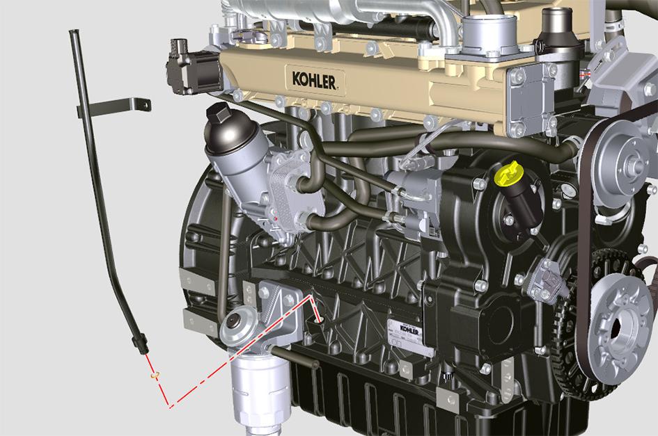
Remove
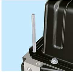
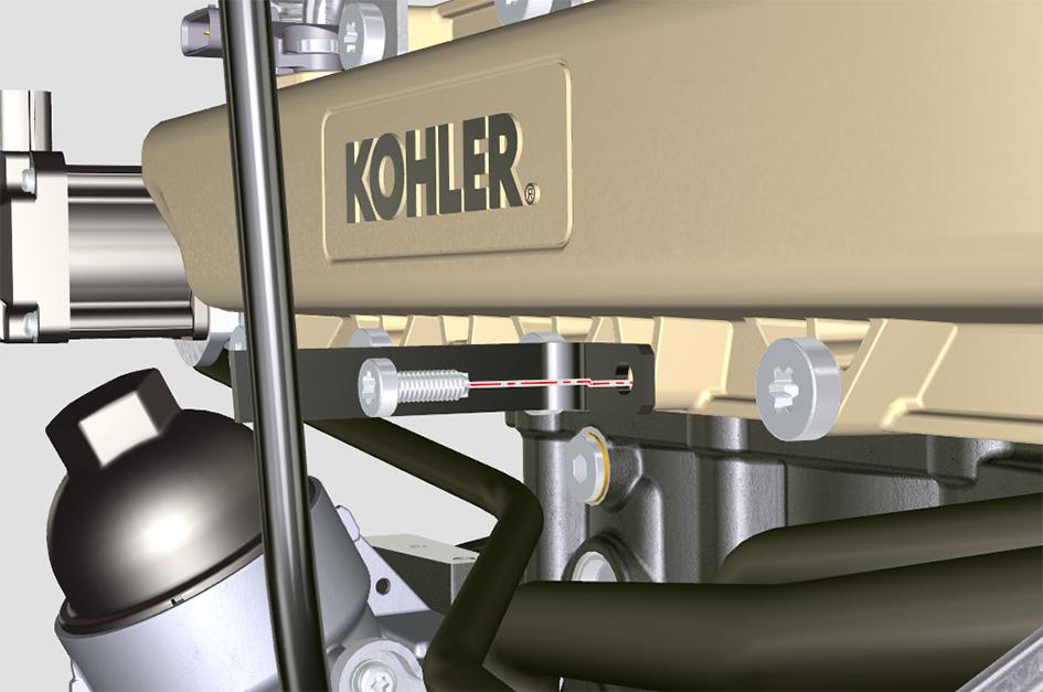
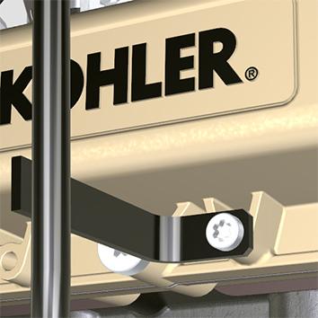
1.Remove the screw.
2.Pull out the oil dipstick pipe in the direction of the arrow.
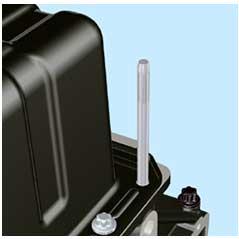
2.Attach the oil dipstick pipe to the crankcase with the screw.
B Dipstick pipe
C Screw
F Manifold
3.Tighten the pipe on the manifold.
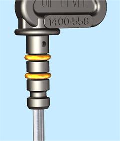
4.Check the gaskets are correctly installed.
A Dipstick
B Dipstick pipe
C Screw
Install
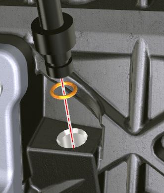
1.Put the new gasket on the seat of the pipe.
264.
A Dipstick
B Dipstick pipe
G Gasket
5.Put the dipstick into the pipe.
After installation
1.Start the engine and check for any leakage.
B Dipstick pipe
D Seat
E Gasket
Suggest:
If the above button click is invalid.
Please download this document first, and then click the above link to download the complete manual.
Thank you so much for reading

51 - Timing Gear
00 - General
Introduction
The timing gears are located inside a casing at the front end of the engine.
The engine must be timed so that the camshaft operates the valves at the correct time relative to the crankshaft position.
Valve timing is achieved by ensuring that the camshaft drive gear is meshed to the crankshaft gear at their correct angular positions, Refer to EngineGeneral, Operation, The Four Stroke Cycle for more information about valve timing.