Service Manual TM310
Service Manual - TM310
Section 1 - General Information
Section 2 - Care and Safety
Section 3 - Routine Maintenance
Section B - Body and Framework
Section C - Electrics
Section E - Hydraulics
Section F - Transmission
Section G - Brakes
Section H - Steering
Section K - Engine
Section M - Network Systems
Publication
Copyright © 2004 JCB SERVICE. All rights reserved. No part of this publication may be reproduced, stored in a retrieval system, or transmitted in any form or by any other means, electronic, mechanical, photocopying or otherwise, without prior permission from JCB SERVICE. World Class Customer Support
9803/9520-9
No. Issued by JCB Technical Publications, JCB Service, World Parts Centre, Beamhurst, Uttoxeter, Staffordshire, ST14 5PA, England. Tel +44 1889 590312 Fax +44 1889 593377
Service Manual - TM310, TM320
Section 1 - General Information
Section 2 - Care and Safety
Section 3 - Routine Maintenance
Section B - Body and Framework
Section C - Electrics
Section E - Hydraulics
Section F - Transmission
Section G - Brakes
Section H - Steering
Section K - Engine
Section M - Network Systems
Copyright © 2004 JCB SERVICE. All rights reserved. No part of this publication may be reproduced, stored in a retrieval system, or transmitted in any form or by any other means, electronic, mechanical, photocopying or otherwise, without prior permission from JCB SERVICE. World Class Customer Support
No. Issued by JCB Technical Publications, JCB Aftermarket Training, Woodseat, Rocester, Staffordshire, ST14 5BW, England. Tel +44 1889 591300 Fax +44 1889 591400 Section
General Information
9803/9520-8 Publication
1
Page No. Contents
1-i 1-i Introduction About this Manual ...................................................................................... 1-1 Machine Model and Serial Number .......................................................1-1 Using the Service Manual .....................................................................1-1 Section Numbering ................................................................................1-1 Left Side, Right Side ..............................................................................1-2 Cross References ..................................................................................1-2 Identifying your Machine ............................................................................ 1-3 Machine Identification Plate ..................................................................1-3 Component Identification Plates ............................................................1-4 Torque Settings Zinc Plated Fasteners and Dacromet Fasteners ....................................... 1-7 Introduction ............................................................................................1-7 Bolts and Screws ...................................................................................1-7 Hydraulic Connections ............................................................................. 1-11 'O' Ring Face Seal System ..................................................................1-11 'Torque Stop' Hose System .................................................................1-14 Service Tools Numerical List .......................................................................................... 1-15 Tool Detail Reference .............................................................................. 1-16 Section B - Body and Framework ........................................................1-16 Section C - Electrics ............................................................................1-20 Section E - Hydraulics .........................................................................1-23 Section H - Steering ............................................................................1-31 Section K - Engine ...............................................................................1-32 Service Consumables Sealing and Retaining Compounds ......................................................... 1-35 Terms and Definitions Colour Coding .......................................................................................... 1-37 Hydraulic Schematic Colour Codes .....................................................1-37
Section 1 - General Information
Introduction
About this Manual
Machine Model and Serial Number
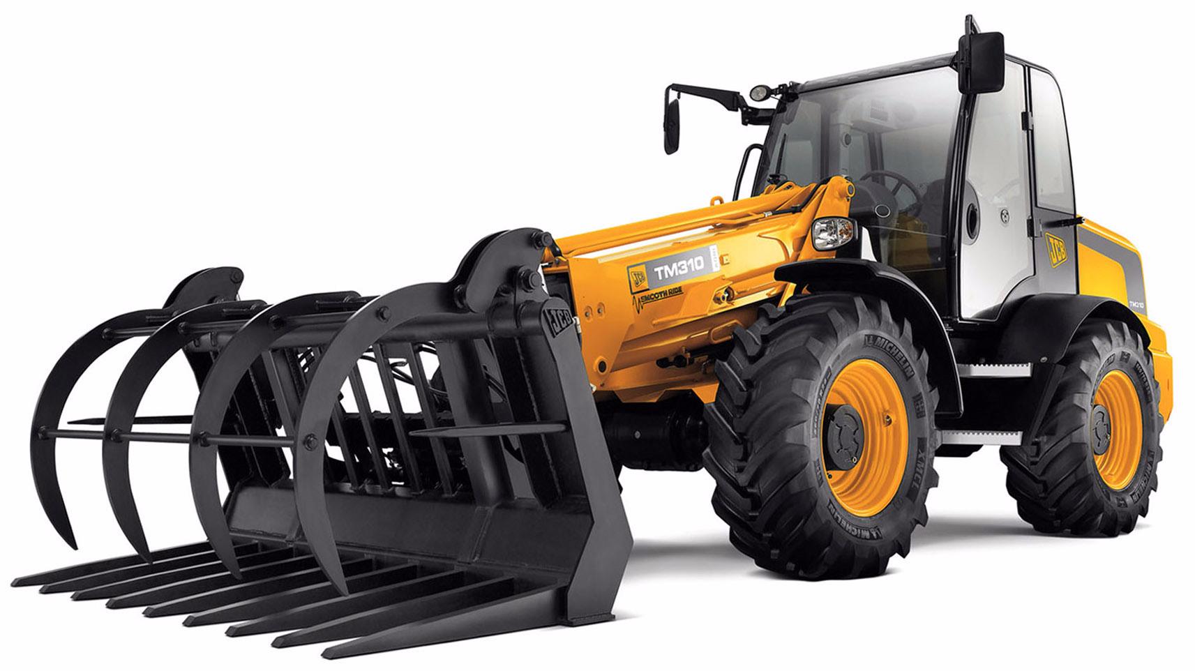
This manual provides information for the following model(s) in the JCB machine range:
–TM310, TM310S and TM310WM from machine serial number 1314700.
–TM320 from machine serial number 1314700.
Using the Service Manual
T11-004
This publication is designed for the benefit of JCB Distributor Service Engineers who are receiving, or have received, training by JCB Technical Training Department.
These personnel should have a sound knowledge of workshop practice, safety procedures, and general techniques associated with the maintenance and repair of hydraulic earthmoving equipment.
The illustrations in this publication are for guidance only. Where the machines differ, the text and/or the illustration will specify.
General warnings in Section 2 are repeated throughout the manual, as well as specific warnings. Read all safety statements regularly, so you do not forget them.
Renewal of oil seals, gaskets, etc., and any component showing obvious signs of wear or damage is expected as a matter of course. It is expected that components will be cleaned and lubricated where appropriate, and that any opened hose or pipe connections will be blanked to prevent excessive loss of hydraulic fluid and ingress of dirt.
Where a torque setting is given as a single figure it may be varied by plus or minus 3%. Torque figures indicated are for dry threads, hence for lubricated threads may be reduced by one third.
The manufacturer's policy is one of continuous improvement. The right to change the specification of the machine without notice is reserved. No responsibility will be accepted for discrepancies which may occur between specifications of the machine and the descriptions contained in this publication.
Finally, please remember above all else safety must come first!
Section Numbering
T11-005
The manual is compiled in sections, the first three are numbered and contain information as follows:
1 General Information - includes torque settings and service tools.
2 Care and Safety - includes warnings and cautions pertinent to aspects of workshop procedures etc.
3 Maintenance - includes service schedules and recommended lubricants for all the machine.
The remaining sections are alphabetically coded and deal with Dismantling, Overhaul etc. of specific components, for example:
A Attachments
B Body and Framework, etc.
Section contents, technical data, circuit descriptions, operation descriptions etc. are inserted at the beginning of each alphabetically coded section.
Section 1 - General Information 1-1 1-1 9803/9520-8
Left Side, Right Side
In this manual, 'left' A and 'right' B mean your left and right when you are seated correctly in the machine.
Cross References
C087420
T1-004_2
In this publication, page cross references are made by presenting the subject title printed in bold, italic and underlined. It is preceeded by the 'go to' symbol. The number of the page upon which the subject begins, is indicated within the brackets. For example: K Cross References ( T 1-2)
Section 1 - General Information Introduction About this Manual 1-2 1-2
9803/9520-8
Fig 1.
Identifying your Machine
Machine Identification Plate
Your machine has an identification plate mounted as shown. The serial numbers of the machine and its major units are stamped on the plate.
Note: The machine model and build specification is indicated by the VIN (earlier machines) or PIN (later machines). Refer to Typical Vehicle Identification Number (VIN) or Typical Product Identification Number (PIN)
The serial number of each major unit is also stamped on the unit itself. If a major unit is replaced by a new one, the serial number on the identification plate will be wrong. Either stamp the new number of the unit on the identification plate, or simply stamp out the old number. This will prevent the wrong unit number being quoted when replacement parts are ordered.
The machine and engine serial numbers can help identify exactly the type of equipment you have.
Identifying your Machine
Typical Product Identification Number (PIN)
T033160-1.
Fig 3.
1 World Manufacturer Identification (3 Digits)
2 Model Number (3 Digits)
3 Loader End Type (1 Digit)
O = HT Loader End
Z = ZX Loader End
4 Designation (1 Digit)
S = Farmmaster
O = None Farmmaster
I = India
5 Check Letter (1 Digit)
The Check Letter is used to verify the authenticity of the machine's PIN.
6 Year of Manufacture (1 Digit)
7 = 2007A = 2010
8 = 2008B = 2011
9 = 2009C = 2012
7 Machine Serial Number (7 Digits)
Each machine has a unique serial number.
C051170-C1
Section 1 - General Information Introduction
1-3 1-3
9803/9520-8
Fig 2.
Typical Vehicle Identification Number
12345
SLPTM3103E1314700
1 World Manufacturer Identification (SLP = JCB)
2 Machine Type (TM310, TM-W, TM320)
3 Year of Manufacture (1 = 2001, 2 = 2002, 3 = 2003, 4 = 2004, 5 = 2005, 6 = 2006, 7 = 2007)
4 Manufacturers Location (E = England)
5 Machine Serial Number (1314700)
Component Identification Plates
Typical Engine Identification Number
Section 1 - General Information Introduction
Identifying your Machine
T1-005_3
Engine data labels A are located on the cylinder block at position C and rocker cover D (if fitted). K Fig 4. ( T 1-4) The data label contains important engine information and includes the engine identification number E
A typical engine identification number is explained as follows:
SA320/40001U0000104
12345
1 Engine Type
S = 4.4 litre series.
JCB Dieselmax (Tier 2)
A = Naturally aspirated
B = Turbocharged
C = Turbocharged and intercooled
JCB Dieselmax (Tier 3)
D = Turbocharged
E = Electronic common rail fuel injection
F = Turbocharged and after-cooled
2 Engine part number
3 Country of manufacture
U = United Kingdom
4 Engine Serial Number
5 Year of Manufacture
The last three parts of the engine identification number are stamped on the cylinder block at position B C007820-C2
U0000104
9803/9520-8
1-4 1-4
Fig 4. Engine
B C D B E
Identifying your Machine
Transmission Identification Numbers
The transmission serial number is stamped on label A which is mounted on the front face.
The drop box serial number is stamped on plate B mounted on the drop box.
The axle serial number is stamped on plate C mounted on the axle.
Section 1 - General Information Introduction
1-5 1-5
9803/9520-8
Fig 5.
Fig 6.
C
Fig 7.
B
FOPS Data Plate !MWARNING
Do not use the machine if the falling objects protection level provided by the structure is not sufficient for the application. Falling objects can cause serious injury. 8-2-8-17
If the machine is used in any application where there is a risk of falling objects then a falling-objects protective structure (FOPS) must be installed. For further information contact your JCB Dealer
The falling objects protection structure (FOPS) is fitted with a dataplate. The dataplate indicates what level protection the structure provides.
There are two levels of FOPS:
– Level I Impact Protection - impact strength for protection from small falling objects (e.g. bricks, small concrete blocks, hand tools) encountered in operations such as highway maintenance, landscaping and other construction site services.
Level II Impact Protection - impact strength for protection from heavy falling objects (e.g. trees, rocks) for machines involved in site clearing, overhead demolition or forestry.
Identifying your Machine
ROPS Data Plate !MWARNING
You could be killed or seriously injured if you operate a machine with a damaged or missing ROPS/FOPS. If the Roll Over Protection Structure (ROPS)/Falling Objects Protection Structure (FOPS) has been in an accident, do not use the machine until the structure has been renewed. Modifications and repairs that are not approved by the manufacturer may be dangerous and will invalidate the ROPS/FOPS certification.
INT-2-1-9_6
!MWARNING
Seat Belts
The ROPS/FOPS is designed to give you protection in an accident. If you do not wear your seat belt, you could be thrown out of the machine and crushed. You must wear a seat belt when using the machine. Fasten the seat belt before starting the engine. 0153
Machines built to FOPS/ROPS standards have a data plate attached to the inside of the cab.
C051290
Section 1 - General Information Introduction
1-6 1-6 9803/9520-8
–
JCBCABSYSTEMSLTD RIVERSIDE,RUGELEY,STAFFORDSHIRE WS152WA,ENGLAND .ROPS/FOPSPARTNo:335/13012 .CERTIFIEDFORJCBTELESCOPICHANDLERSOF MAX.UNLADENMASS:10,250Kg .CERTIFIEDTOEN13627:2000LEVEL2:FOPS .CERTIFIEDTOEN13510:2000:ROPS 817/20828 A
Fig 8.
C051290
Torque Settings
Zinc Plated Fasteners and Dacromet Fasteners
Torque Settings
Zinc Plated Fasteners and Dacromet Fasteners
T11-002
Introduction
Some external fasteners on JCB machines are manufactured using an improved type of corrosion resistant finish. This type of finish is called Dacromet and replaces the original Zinc and Yellow Plating used on earlier machines.
The two types of fasteners can be readily identified by colour and part number suffix. K Table 1. Fastener Types ( T 1-7)
Fastener Type ColourPart No. Suffix
Zinc and Yellow Golden finish'Z' (e.g. 1315/3712Z)
DacrometMottled silver finish'D' (e.g. 1315/3712D)
Note: As the Dacromet fasteners have a lower torque setting than the Zinc and Yellow fasteners, the torque figures used must be relevant to the type of fastener.
Note: A Dacromet bolt should not be used in conjunction with a Zinc or Yellow plated nut, as this could change the torque characteristics of the torque setting further. For the same reason, a Dacromet nut should not be used with a Zinc or Yellow plated bolt.
Note: All bolts used on JCB machines are high tensile and must not be replaced by bolts of a lesser tensile specification.
Note: Dacromet bolts, due to their high corrosion resistance are used in areas where rust could occur. Dacromet bolts are only used for external applications. They are not used in applications such as gearbox or engine joint seams or internal applications.
Bolts and Screws
Use the following torque setting tables only where no torque setting is specified in the text.
Note: Dacromet fasteners are lubricated as part of the plating process, do not lubricate.
Torque settings are given for the following conditions:
Condition 1
–Un-lubricated fasteners
–Zinc fasteners
–Yellow plated fasteners
Condition 2
–Zinc flake (Dacromet) fasteners
–Lubricated zinc and yellow plated fasteners
–Where there is a natural lubrication. For example, cast iron components
Verbus Ripp Bolts
Torque settings for these bolts are determined by the application. Refer to the relevant procedure for the required settings.
Section 1 - General Information
1-7 1-7
9803/9520-8
Table 1. Fastener Types
Fig 9.
Section 1 - General Information
Torque Settings
Zinc Plated Fasteners and Dacromet Fasteners
Bolt SizeHexagon (A/F)Condition 1Condition 2
1-8 1-8
9803/9520-8
Table 2. Torque Settings - UNF Grade 'S' Fasteners
Bolt SizeHexagon (A/F)Condition 1Condition 2 in.mmin.Nmkgf mlbf ftNmkgf mlbf ft 1/46.37/1611.21.18.310.01.07.4 5/167.91/222.32.316.420.02.014.7 3/89.59/1640.04.129.536.03.726.5 7/1611.15/864.06.547.257.05.842.0 1/212.73/498.0010.072.388.09.064.9 9/1614.313/16140.014.3103.2126.012.892.9 5/815.915/16196.020.0144.6177.018.0130.5 3/419.01 1/8343.035.0253.0309.031.5227.9 7/822.21 15/16547.055.8403.4492.050.2362.9 125.41 1/2814.083.0600.4732.074.6539.9 1 1/831.71 7/81181.0120.4871.11063.0108.4784.0 1 1/438.12 1/41646.0167.81214.01481.0151.01092.3
Table 3. Torque Settings - Metric Grade 8.8 Fasteners
ISO Metric ThreadmmmmNmkgf mlbf ftNmkgf mlbf ft M5585.80.64.35.20.53.8 M66109.91.07.39.00.96.6 M881324.02.417.722.02.216.2 M10101747.04.834.743.04.431.7 M12121983.08.561.274.07.554.6 M161624205.020.9151.2184.018.8135.7 M202030400.040.8295.0360.036.7265.5 M242436690.070.4508.9621.063.3458.0 M3030461372.0139.91011.91235.0125.9910.9 M3636552399.0244.61769.42159.0220.01592.4
Section 1 - General Information
Torque Settings
Zinc Plated Fasteners and Dacromet Fasteners
1-9 1-9
9803/9520-8
Table 4. Metric Grade 10.9 Fasteners
SizeHexagon (A/F)Condition 1Condition 2 ISO Metric ThreadmmmmNmkgf mlbf ftNmkgf mlbf ft M5588.10.86.07.30.75.4 M661013.91.410.212.51.39.2 M881334.03.525.030.03.022.1 M10101767.06.849.460.06.144.2 M121219116.011.885.5104.010.676.7 M161624288.029.4212.4259.026.4191.0 M202030562.057.3414.5506.051.6373.2 M242436971.099.0716.9874.089.1644.6 M3030461930.0196.81423.51737.0177.11281.1 M3636553374.0344.02488.53036.0309.62239.2 Bolt SizeHexagon (A/F)Condition 1Condition 2 ISO Metric ThreadmmmmNmkgf mlbf ftNmkgf mlbf ft M5589.81.07.28.80.96.5 M661016.61.712.215.01.511.1 M881340.04.129.536.03.726.5 M10101780.08.159.072.07.353.1 M121219139.014.2102.5125.012.792.2 M161624345.035.2254.4311.031.7229.4 M202030674.068.7497.1607.061.9447.7 M2424361165.0118.8859.21048.0106.9773.0 M3030462316.0236.21708.22084.0212.51537.1 M3636554049.0412.92986.43644.0371.62687.7
Table 5. Metric Grade 12.9 Fasteners
Bolt
Section 1 - General Information
Torque Settings
Zinc Plated Fasteners and Dacromet Fasteners
1-10 1-10 9803/9520-8
Table 6. Torque Settings - Rivet Nut Bolts/Screws
Bolt Size
mlbf ft ISO Metric Threadmm M331.20.10.9 M443.00.32.0 M556.00.64.5 M6610.01.07.5 M8824.02.518.0 M101048.04.935.5 M121282.08.460.5 Bolt Size Nmkgf mlbf ft ISO Metric Thread M32.00.21.5 M46.00.64.5 M511.01.18.0 M619.01.914.0 M846.04.734.0 M1091.09.367.0 M12159.016.2117.0 M16395.040.0292.0 M18550.056.0406.0 M20770.079.0568.0 M241332.0136.0983.0
Table 7. Torque Settings - Internal Hexagon Headed Cap Screws (Zinc)
Nmkgf
Hydraulic Connections
Torque Settings
Hydraulic Connections
'O' Ring Face Seal System
Adaptors Screwed into Valve Blocks
Adaptor screwed into valve blocks, seal onto an 'O' ring which is compressed into a 45° seat machined into the face of the tapped port.
Section 1 - General Information
1-11 1-11 9803/9520-8
T11-003
Table 8. Torque Settings - BSP Adaptors
BSP Adaptor Size Hexagon (A/F) Nmkgf mlbf ft in.mm 1/419.018.01.813.0 3/822.031.03.223.0 1/227.049.05.036.0 5/830.060.06.144.0 3/432.081.08.260.0 138.0129.013.195.0 1 1/450.0206.021.0152.0 SAE Tube Size SAE Port Thread Size Hexagon (A/F) Nmkgf mlbf ft mm 47/16 - 2015.920.0 - 28.02.0 - 2.816.5 - 18.5 69/16 - 1819.146.0 - 54.04.7 - 5.534.0 - 40.0 83/4 - 1622.295.0 - 105.09.7 - 10.769.0 - 77.0 107/8 - 1427.0130.0 - 140.013.2 - 14.396.0 - 104.0 121 1/16 - 1231.8190.0 - 210.019.4 - 21.4141.0 - 155.0 161 5/16 - 1238.1290.0 - 310.029.6 - 31.6216.0 - 230.0 201 5/847.6280.0 - 380.028.5 - 38.7210.0 - 280.0
Table 9. Torque Settings - SAE Connections
Hoses Screwed into Adaptors
Torque Settings
Hydraulic Connections
Hoses 10-B screwed into adaptors 10-A seal onto an `O' ring 10-C which is compressed into a 45° seat machined into the face of the adaptor port.
Note: Dimension 10-D will vary depending upon the torque applied.
Section 1 - General Information
1-12 1-12 9803/9520-8
Fig 10.
BSP Hose SizeHexagon (A/F) Nmkgf mlbf ft in.mm 1/814.014.0 - 16.001.4 - 1.610.3 - 11.8 1/419.024.0 - 27.02.4 - 2.717.7 - 19.9 3/822.033.0 - 40.03.4 - 4.124.3 - 29.5 1/227.044.0 - 50.04.5 - 5.132.4 - 36.9 5/830.058.0 - 65.05.9 - 6.642.8 - 47.9 3/432.084.0 - 92.08.6 - 9.461.9 - 67.8 138.0115.0 - 126.011.7 - 12.884.8 - 92.9 1 1/450.0189.0 - 200.019.3 - 20.4139.4 - 147.5 1 1/255.0244.0 - 260.024.9 - 26.5180.0 - 191.8
Table 10. BSP Hose - Torque Settings
Adaptors into Component Connections with Bonded Washers
Section 1 - General Information
Connections 1-13 1-13 9803/9520-8
Torque Settings Hydraulic
BSP Size Nmkgf mlbf ft in. 1/820.02.115.0 1/434.03.425.0 3/875.07.655.0 1/2102.010.375.0 5/8122.012.490.0 3/4183.018.7135.0 1203.020.7150.0 1 1/4305.031.0225.0 1 1/2305.031.0225.0
Table 11. BSP Adaptors with Bonded Washers - Torque Settings
Service Manual - TM310, TM320
Section 1 - General Information
Section 2 - Care and Safety
Section 3 - Routine Maintenance
Section B - Body and Framework
Section C - Electrics
Section E - Hydraulics
Section F - Transmission
Section G - Brakes
Section H - Steering
Section K - Engine
Section M - Network Systems
Copyright © 2004 JCB SERVICE. All rights reserved. No part of this publication may be reproduced, stored in a retrieval system, or transmitted in any form or by any other means, electronic, mechanical, photocopying or otherwise, without prior permission from JCB SERVICE. World Class Customer Support
No. Issued by JCB Technical Publications, JCB Aftermarket Training, Woodseat, Rocester, Staffordshire, ST14 5BW, England. Tel +44 1889 591300 Fax +44 1889 591400 Section
Care
9803/9520-8 Publication
2
and Safety
Page No. Contents
2-i 2-i Safety Notices Important Information ................................................................................ 2-1 The Operator Manual ............................................................................2-1 Safety Warnings ....................................................................................2-1 Safety Check List ....................................................................................... 2-2 Safety - Yours and Others .....................................................................2-2 General Safety ......................................................................................2-2 Operating Safety ...................................................................................2-4 Maintenance Safety ...............................................................................2-7 Safety Labels ........................................................................................... 2-12 Introduction ..........................................................................................2-12 Safety Label Identification ...................................................................2-12 Part Numbers and Descriptions ..........................................................2-14
Section 2 - Care and Safety
Safety Notices
Important Information
T1-042
The Operator Manual
!MWARNING
You and others can be killed or seriously injured if you operate or maintain the machine without first studying the Operator Manual. You must understand and follow the instructions in the Operator Manual. If you do not understand anything, ask your employer or JCB dealer to explain it.
INT-1-4-2
Do not operate the machine without an Operator Manual, or if there is anything on the machine you do not understand.
Treat the Operator Manual as part of the machine. Keep it clean and in good condition. Replace the Operator Manual immediately if it is lost, damaged or becomes unreadable.
Safety Warnings
This safety alert system identifies important safety messages in this manual. When you see this symbol, be alert, your safety is involved, carefully read the message that follows, and inform other operators.
In this publication and on the machine, there are safety notices. Each notice starts with a signal word. The signal word meanings are given below.
!MDANGER
Denotes an extreme hazard exists. If proper precautions are not taken, it is highly probable that the operator (or others) could be killed or seriously injured.
INT-1-2-1
!MWARNING
Denotes a hazard exists. If proper precautions are not taken, the operator (or others) could be killed or seriously injured.
INT-1-2-2
!MCAUTION
Denotes a reminder of safety practices. Failure to follow these safety practices could result in injury to the operator (or others) and possible damage to the machine.
INT-1-2-3
Section 2 - Care and Safety 2-1 2-1
9803-9520-8
Safety Check List
P4-1004_3
Safety - Yours and Others
General Safety
INT-1-3-1_3
All machinery can be hazardous. When a machine is correctly operated and properly maintained, it is a safe machine to work with. But when it is carelessly operated or poorly maintained it can become a danger to you (the operator) and others.
In this manual and on the machine you will find warning messages. Read and understand them. They tell you of potential hazards and how to avoid them. If you do not fully understand the warning messages, ask your employer or JCB distributor to explain them.
But safety is not just a matter of responding to the warnings. All the time you are working on or with the machine you must be thinking what hazards there might be and how to avoid them.
Do not work with the machine until you are sure that you can control it.
Do not start any job until you are sure that you and those around you will be safe.
If you are unsure of anything, about the machine or the job, ask someone who knows. Do not assume anything.
!MWARNING
T1-043
To operate the machine safely you must know the machine and have the skill to use it. You must abide by all relevant laws, health and safety regulations that apply to the country you are operating in. The Operator Manual instructs you on the machine, its controls and its safe operation; it is not a training manual. If you are a new operator, get yourself trained in the skills of using a machine before trying to work with it. If you don't, you will not do your job well, and you will be a danger to yourself and others.
INT-1-4-1
!MWARNING
Care and Alertness
All the time you are working with or on the machine, take care and stay alert. Always be careful. Always be alert for hazards.
INT-1-3-5
!MWARNING Clothing
You can be injured if you do not wear the proper clothing. Loose clothing can get caught in the machinery. Wear protective clothing to suit the job. Examples of protective clothing are: a hard hat, safety shoes, safety glasses, a well fitting overall, earprotectors and industrial gloves. Keep cuffs fastened. Do not wear a necktie or scarf. Keep long hair restrained. Remove rings, watches and personal jewellery.
INT-1-3-6_2
!MWARNING
Alcohol and Drugs
It is extremely dangerous to operate machinery when under the influence of alcohol or drugs. Do not consume alcoholic drinks or take drugs before or while operating the machine or attachments. Be aware of medicines which can cause drowsiness.
INT-1-3-9_2
9803-9520-8
Section 2 - Care and Safety Safety Notices Safety Check List 2-2 2-2
Remember BE CAREFUL BE ALERT BE SAFE
!MWARNING
Feeling Unwell
Do not attempt to operate the machine if you are feeling unwell. By doing so you could be a danger to yourself and those you work with.
8-1-2-4
!MWARNING
Mobile Phones
Switch off your mobile phone before entering an area with a potentially explosive atmosphere. Sparks in such an area could cause an explosion or fire resulting in death or serious injury.
Switch off and do not use your mobile phone when refuelling the machine.
INT-3-3-9
!MWARNING
Lifting Equipment
You can be injured if you use incorrect or faulty lifting equipment. You must identify the weight of the item to be lifted then choose lifting equipment that is strong enough and suitable for the job. Make sure that lifting equipment is in good condition and complies with all local regulations.
INT-1-3-7_2
!MWARNING
Raised Equipment
Never walk or work under raised equipment unless it is supported by a mechanical device. Equipment which is supported only by a hydraulic device can drop and injure you if the hydraulic system fails or if the control is operated (even with the engine stopped).
Make sure that no-one goes near the machine while you install or remove the mechanical device.
13-2-3-7_3
!MWARNING
Raised Machine
NEVER position yourself or any part of your body under a raised machine which is not properly supported. If the machine moves unexpectedly you could become trapped and suffer serious injury or be killed.
INT-3-3-7_1
!MDANGER
Lightning
Lightning can kill you. Do not use the machine if there is lightning in your area.
5-1-1-2
!MWARNING
Machine Modifications
This machine is manufactured in compliance with legislative and other requirements. It should not be altered in any way which could affect or invalidate any of these requirements. For advice consult your JCB Distributor.
INT-1-3-10_2
Section 2 - Care and Safety Safety Notices Safety Check List 2-3 2-3
9803-9520-8
Operating Safety
!MWARNING Machine Condition
A defective machine can injure you or others. Do not operate a machine which is defective or has missing parts. Make sure the maintenance procedures in this manual are completed before using the machine.
INT-2-1-2_2
!MWARNING Machine Limits
Operating the machine beyond its design limits can damage the machine, it can also be dangerous. Do not operate the machine outside its limits. Do not try to upgrade the machine performance with unapproved modifications.
INT-2-1-4
!MWARNING Engine/Steering Failure
If the engine or steering fails, stop the machine as quickly as possible. Do not operate the machine until the fault has been corrected.
INT-2-1-5
!MWARNING Exhaust Gases
Breathing the machine exhaust gases can harm and possibly kill you. Do not operate the machine in closed spaces without making sure there is good ventilation. If possible, fit an exhaust extension. If you begin to feel drowsy, stop the machine at once and get into fresh air.
INT-2-1-10_2
!MWARNING
Work Sites
Work sites can be hazardous. Inspect the site before working on it. You could be killed or injured if the ground gives way under your machine or if piled material collapses onto it. Check for potholes and hidden debris, logs, ironwork etc. Any of these could cause you to lose control of your machine. Check for utilities such as electric cables (overhead and underground), gas and water pipes etc. Mark the positions of the underground cables and pipes. Make sure that you have enough clearance beneath overhead cables and structures.
INT-2-2-1_2
!MWARNING Communications
Bad communications can cause accidents. Keep people around you informed of what you will be doing. If you will be working with other people, make sure any hand signals that may be used are understood by everybody. Work sites can be noisy, do not rely on spoken commands.
INT-2-2-3
!MWARNING Parking
An incorrectly parked machine can move without an operator. Follow the instructions in the Operator Manual to park the machine correctly.
INT-2-2-4_2
!MWARNING
Banks and Trenches
Banked material and trenches can collapse. Do not work or drive too close to banks and trenches where there is danger of collapse.
INT-2-2-5
!MWARNING
Before moving the machine onto the trailer, make sure that the trailer and ramp are free from oil, grease and ice. Remove oil, grease and ice from the machine tyres. Make sure the machine will not foul on the ramp angle. See Static Dimensions in SPECIFICATION section for the minimum ground clearance of your machine.
2-2-7-5_1
9803-9520-8
Section 2 - Care and Safety Safety Notices Safety Check List 2-4 2-4
Suggest:
If the above button click is invalid.
Please download this document first, and then click the above link to download the complete manual.
Thank you so much for reading

!MWARNING Safety Barriers
Unguarded machines in public places can be dangerous. In public places, or where your visibility is reduced, place barriers around the work area to keep people away.
INT-2-2-8
!MDANGER Sparks
Explosions and fire can be caused by sparks from the exhaust or the electrical system. Do not use the machine in closed areas where there is flammable material, vapour or dust.
INT-2-2-10
!MWARNING Hazardous Atmospheres
This machine is designed for use in normal out door atmospheric conditions. It should not be used in an enclosed area without adequate ventilation. Do not use the machine in a potentially explosive atmosphere, i.e. combustible vapours, gas or dust, without first consulting your JCB Distributor.
INT-2-1-14
!MCAUTION Regulations
Obey all laws, work site and local regulations which affect you and your machine.
INT-1-3-3
!MWARNING Practice
You or others can be killed or seriously injured if you do unfamiliar operations without first practising them. Practise away from the work site on a clear area. Keep other people away. Do not perform new operations until you are sure you can do them safely.
INT-2-1-1
!MWARNING
Airborne particles of light combustible material such as straw, grass, wood shavings, etc. must not be allowed to accumulate within the engine compartment or in the propshaft guards (when fitted). Inspect these areas frequently and clean at the beginning of each work shift or more often if required. Before opening the engine cover, ensure that the top is clear of debris.
5-3-1-12_3
!MWARNING
Keep the machine controls clean and dry. Your hands and feet could slide off slippery controls. If that happens you could lose control of the machine.
2-2-3-6
!MWARNING Visibility
Accidents can be caused by working in poor visibility. Use your lights to improve visibility. Keep the road lights, windows and mirrors clean.
Do not operate the machine if you cannot see clearly.
5-1-4-7
!MWARNING
Electrical Power Cables
You could be electrocuted or badly burned if you get the machine or its attachments too close to electrical power cables.
You are strongly advised to make sure that the safety arrangements on site comply with the local laws and regulations concerning work near electric power lines.
Before you start using the machine, check with your electricity supplier if there are any buried power cables on the site.
There is a minimum clearance required for working beneath overhead power cables. You must obtain details from your local electricity supplier.
2-2-5-4
Section 2 - Care and Safety Safety Notices Safety Check List 2-5 2-5
9803-9520-8
!MCAUTION
If you have an attachment which is not covered in the Operator Manual do not install it, use it or remove it until you have obtained, read and understood the pertinent information. Install attachments only on the machines for which they were designed.
5-5-1-1_2
!MWARNING
Use only the JCB approved attachments that are specified for your machine. Operating with nonspecified attachments can overload the machine, causing possible damage and machine instability which could result in injury to yourself or others.
The use of non-approved attachments could invalidate your warranty.
2-4-5-2_1
!MDANGER Working Platform
Using the machine as a working platform is hazardous; you can fall off and be killed or injured. Never use the machine as a working platform.
5-1-5-9
!MWARNING
The engine has exposed rotating parts. Switch OFF the engine before working in the engine compartment. Do not use the machine with the engine cover open.
5-2-6-5
!MWARNING
You could be killed or seriously injured if you operate a machine with a damaged or missing ROPS/FOPS. If the Roll Over Protection Structure (ROPS)/Falling Objects Protection Structure (FOPS) has been in an accident, do not use the machine until the structure has been renewed. Modifications and repairs that are not approved by the manufacturer may be dangerous and will invalidate the ROPS/FOPS certification.
INT-2-1-9_6
!MWARNING
Travelling at High Speeds
Travelling at high speeds can cause accidents. Do not reverse in a high gear with full throttle. Always travel at a safe speed to suit working conditions.
INT-5-3-3
!MWARNING
High Loads
A high load can block your view and reduce the machine's stability. Travel with the load low to the ground. Travel slowly and with caution over rough, muddy or loose surfaces.
5-1-3-2
!MWARNING
Slopes
When transporting a load on a slope, drive slowly and keep the load uphill of the machine. This will increase stability.
5-1-4-1
!MWARNING
Hillsides
Operating the machine on hillsides can be dangerous if proper precautions are not taken. Ground conditions can be changed by rain, snow, ice etc. Check the site carefully. Operate in first gear on hillsides, when applicable, keep all attachments low to the ground. Never coast down a hill with the engine off or the transmission in neutral.
INT-2-2-7
!MWARNING
Controls
You or others can be killed or seriously injured if you operate the control levers from outside the machine. Operate the control levers only when you are correctly seated.
0179_2
!MCAUTION
Passengers
Passengers in or on the machine can cause accidents. Do not carry passengers.
INT-2-2-2_1
Section 2 - Care and Safety Safety Notices Safety Check List 2-6 2-6
9803-9520-8