Service Manual TM310

Service Manual - Service Manual
Section 1 - General Information
Section 2 - Care and Safety
Section 3 - Routine Maintenance
Section B - Body and Framework
Section C - Electrics
Section E - Hydraulics

Section F - Transmission
Section G - Brakes
Section H - Steering
Section K - Engine
Section M - Network Systems
Publication
Copyright © 2004 JCB SERVICE. All rights reserved. No part of this publication may be reproduced, stored in a retrieval system, or transmitted in any form or by any other means, electronic, mechanical, photocopying or otherwise, without prior permission from JCB SERVICE. World Class Customer Support
9803/9520-7
No. Issued by JCB Technical Publications, JCB Service, World Parts Centre, Beamhurst, Uttoxeter, Staffordshire, ST14 5PA, England. Tel +44 1889 590312 Fax +44 1889 593377
Notes:
Section 1 - 1 1-0 1-0 9803/9520-07
Page No. Contents
1-i 1-i Introduction About this Manual ...................................................................................... 1-1 Machine Model and Serial Number .......................................................1-1 Using the Service Manual .....................................................................1-1 Section Numbering ................................................................................1-1 Left Side, Right Side ..............................................................................1-2 Cross References ..................................................................................1-2 Identifying your Machine ............................................................................ 1-3 Machine Identification Plate ..................................................................1-3 Component Identification Plates ............................................................1-4 Torque Settings Zinc Plated Fasteners and Dacromet Fasteners ....................................... 1-7 Introduction ............................................................................................1-7 Bolts and Screws ...................................................................................1-7 Hydraulic Connections ............................................................................. 1-11 'O' Ring Face Seal System ..................................................................1-11 'Torque Stop' Hose System .................................................................1-14 Service Tools Numerical List .......................................................................................... 1-15 Tool Detail Reference .............................................................................. 1-16 Section B - Body and Framework ........................................................1-16 Section C - Electrics ............................................................................1-20 Section E - Hydraulics .........................................................................1-23 Section H - Steering ............................................................................1-31 Section K - Engine ...............................................................................1-32 Service Consumables Sealing and Retaining Compounds ......................................................... 1-35 Terms and Definitions Colour Coding .......................................................................................... 1-37 Hydraulic Schematic Colour Codes .....................................................1-37
Section 1 - General Information
Page No. Contents Section 1 - General Information 1-ii 1-ii
Introduction
About this Manual
Machine Model and Serial Number
This manual provides information for the following model(s) in the JCB machine range:
–TM310, TM310S and TM310WM from machine serial number 1314700.
Using the Service Manual
T11-004
This publication is designed for the benefit of JCB Distributor Service Engineers who are receiving, or have received, training by JCB Technical Training Department.
These personnel should have a sound knowledge of workshop practice, safety procedures, and general techniques associated with the maintenance and repair of hydraulic earthmoving equipment.
The illustrations in this publication are for guidance only. Where the machines differ, the text and/or the illustration will specify.
General warnings in Section 2 are repeated throughout the manual, as well as specific warnings. Read all safety statements regularly, so you do not forget them.
Renewal of oil seals, gaskets, etc., and any component showing obvious signs of wear or damage is expected as a matter of course. It is expected that components will be cleaned and lubricated where appropriate, and that any opened hose or pipe connections will be blanked to prevent excessive loss of hydraulic fluid and ingress of dirt.
Where a torque setting is given as a single figure it may be varied by plus or minus 3%. Torque figures indicated are for dry threads, hence for lubricated threads may be reduced by one third.
The manufacturer's policy is one of continuous improvement. The right to change the specification of the machine without notice is reserved. No responsibility will be accepted for discrepancies which may occur between specifications of the machine and the descriptions contained in this publication.
Finally, please remember above all else safety must come first!
Section Numbering
T11-005
The manual is compiled in sections, the first three are numbered and contain information as follows:
1 General Information - includes torque settings and service tools.
2 Care and Safety - includes warnings and cautions pertinent to aspects of workshop procedures etc.
3 Maintenance - includes service schedules and recommended lubricants for all the machine.
The remaining sections are alphabetically coded and deal with Dismantling, Overhaul etc. of specific components, for example:
A Attachments
B Body and Framework, etc.
Section contents, technical data, circuit descriptions, operation descriptions etc. are inserted at the beginning of each alphabetically coded section.
Section 1 - General Information 1-1 1-1 9803/9520-07
Left Side, Right Side
In this manual, 'left' A and 'right' B mean your left and right when you are seated correctly in the machine.
Cross References
C087420
T1-004_2
In this publication, page cross references are made by presenting the subject title printed in bold, italic and underlined. It is preceeded by the 'go to' symbol. The number of the page upon which the subject begins, is indicated within the brackets. For example: K Cross References ( T 1-2)
Section 1 - General Information Introduction About this Manual 1-2 1-2
9803/9520-07
Fig 1.
Identifying your Machine
Machine Identification Plate
Your machine has an identification plate mounted as shown. The serial numbers of the machine and its major units are stamped on the plate.
Note: The machine model and build specification is indicated by the VIN (earlier machines) or PIN (later machines). Refer to Typical Vehicle Identification Number (VIN) or Typical Product Identification Number (PIN)
The serial number of each major unit is also stamped on the unit itself. If a major unit is replaced by a new one, the serial number on the identification plate will be wrong. Either stamp the new number of the unit on the identification plate, or simply stamp out the old number. This will prevent the wrong unit number being quoted when replacement parts are ordered.
The machine and engine serial numbers can help identify exactly the type of equipment you have.
Identifying your Machine
Typical Product Identification Number (PIN)
T033160-1.
Fig 3.
1 World Manufacturer Identification (3 Digits)
2 Model Number (3 Digits)
3 Loader End Type (1 Digit)
O = HT Loader End
Z = ZX Loader End
4 Designation (1 Digit)
S = Farmmaster
O = None Farmmaster
I = India
5 Check Letter (1 Digit)
The Check Letter is used to verify the authenticity of the machine's PIN.
6 Year of Manufacture (1 Digit)
7 = 2007A = 2010
8 = 2008B = 2011
9 = 2009C = 2012
7 Machine Serial Number (7 Digits)
Each machine has a unique serial number.
C051170-C1
Section 1 - General Information Introduction
1-3 1-3
9803/9520-07
Fig 2.
Typical Vehicle Identification Number
12345
SLPTM3103E1314700
1 World Manufacturer Identification (SLP = JCB)
2 Machine Type (TM310, TM-W)
3 Year of Manufacture (1 = 2001, 2 = 2002, 3 = 2003, 4 = 2004, 5 = 2005, 6 = 2006, 7 = 2007)
4 Manufacturers Location (E = England)
5 Machine Serial Number (1314700)
Component Identification Plates
Typical Engine Identification Number
Section 1 - General Information Introduction
Identifying your Machine
T1-005_3
Engine data labels A are located on the cylinder block at position C and rocker cover D (if fitted). K Fig 4. ( T 1-4) The data label contains important engine information and includes the engine identification number E
A typical engine identification number is explained as follows:
SA320/40001U0000104
12345
1 Engine Type
S = 4.4 litre series.
JCB Dieselmax (Tier 2)
A = Naturally aspirated
B = Turbocharged
C = Turbocharged and intercooled
JCB Dieselmax (Tier 3)
D = Turbocharged
E = Electronic common rail fuel injection
F = Turbocharged and after-cooled
2 Engine part number
3 Country of manufacture
U = United Kingdom
4 Engine Serial Number
5 Year of Manufacture
The last three parts of the engine identification number are stamped on the cylinder block at position B C007820-C2
U0000104
9803/9520-07
1-4 1-4
Fig 4. Engine
B C D B E
Identifying your Machine
Transmission Identification Numbers
The transmission serial number is stamped on label A which is mounted on the front face.
The drop box serial number is stamped on plate B mounted on the drop box.
The axle serial number is stamped on plate C mounted on the axle.
Section 1 - General Information Introduction
1-5 1-5
9803/9520-07
Fig 5.
Fig 6.
B C
Fig 7.
FOPS Data Plate !MWARNING
Do not use the machine if the falling objects protection level provided by the structure is not sufficient for the application. Falling objects can cause serious injury. 8-2-8-17
If the machine is used in any application where there is a risk of falling objects then a falling-objects protective structure (FOPS) must be installed. For further information contact your JCB Dealer
The falling objects protection structure (FOPS) is fitted with a dataplate. The dataplate indicates what level protection the structure provides.
There are two levels of FOPS:
– Level I Impact Protection - impact strength for protection from small falling objects (e.g. bricks, small concrete blocks, hand tools) encountered in operations such as highway maintenance, landscaping and other construction site services.
Level II Impact Protection - impact strength for protection from heavy falling objects (e.g. trees, rocks) for machines involved in site clearing, overhead demolition or forestry.
Identifying your Machine
ROPS Data Plate !MWARNING
You could be killed or seriously injured if you operate a machine with a damaged or missing ROPS/FOPS. If the Roll Over Protection Structure (ROPS)/Falling Objects Protection Structure (FOPS) has been in an accident, do not use the machine until the structure has been renewed. Modifications and repairs that are not approved by the manufacturer may be dangerous and will invalidate the ROPS/FOPS certification.
INT-2-1-9_6
!MWARNING
Seat Belts
The ROPS/FOPS is designed to give you protection in an accident. If you do not wear your seat belt, you could be thrown out of the machine and crushed. You must wear a seat belt when using the machine. Fasten the seat belt before starting the engine. 0153
Machines built to FOPS/ROPS standards have a data plate attached to the inside of the cab.
C051290
Section 1 - General Information Introduction
1-6 1-6
9803/9520-07
–
YEAR: COMPLIES TO ISO 3471:1994 EN 13510:2000 JCB TELESCOPIC TM310 SERIAL NO FOPS: COMPLIES TO ISO 3449:1992 EN 13627: 2000 LEVEL 1 J.C.B. CAB SYSTEMS LAKESIDE WORKS ROCESTER UTTOXETER, STAFFS ST14 5JP ENGLAND CAB PART NO 332/P6978 332/A5590 MAXIMUM UNLADEN MASS 10,250Kg
Fig 8.
Torque Settings
Zinc Plated Fasteners and Dacromet Fasteners
Torque Settings
Zinc Plated Fasteners and Dacromet Fasteners
T11-002
Introduction
Some external fasteners on JCB machines are manufactured using an improved type of corrosion resistant finish. This type of finish is called Dacromet and replaces the original Zinc and Yellow Plating used on earlier machines.
The two types of fasteners can be readily identified by colour and part number suffix. K Table 1. Fastener Types ( T 1-7)
Fastener Type ColourPart No. Suffix
Zinc and Yellow Golden finish'Z' (e.g. 1315/3712Z)
DacrometMottled silver finish'D' (e.g. 1315/3712D)
Note: As the Dacromet fasteners have a lower torque setting than the Zinc and Yellow fasteners, the torque figures used must be relevant to the type of fastener.
Note: A Dacromet bolt should not be used in conjunction with a Zinc or Yellow plated nut, as this could change the torque characteristics of the torque setting further. For the same reason, a Dacromet nut should not be used with a Zinc or Yellow plated bolt.
Note: All bolts used on JCB machines are high tensile and must not be replaced by bolts of a lesser tensile specification.
Note: Dacromet bolts, due to their high corrosion resistance are used in areas where rust could occur. Dacromet bolts are only used for external applications. They are not used in applications such as gearbox or engine joint seams or internal applications.
Bolts and Screws
Use the following torque setting tables only where no torque setting is specified in the text.
Note: Dacromet fasteners are lubricated as part of the plating process, do not lubricate.
Torque settings are given for the following conditions:
Condition 1
–Un-lubricated fasteners
–Zinc fasteners
–Yellow plated fasteners
Condition 2
–Zinc flake (Dacromet) fasteners
–Lubricated zinc and yellow plated fasteners
–Where there is a natural lubrication. For example, cast iron components
Verbus Ripp Bolts
Torque settings for these bolts are determined by the application. Refer to the relevant procedure for the required settings.
Section 1 - General Information
1-7 1-7
9803/9520-07
Table 1. Fastener Types
Fig 9.
Section 1 - General Information
Torque Settings
Zinc Plated Fasteners and Dacromet Fasteners
Bolt SizeHexagon (A/F)Condition 1Condition 2
1-8 1-8 9803/9520-07
Table 2. Torque Settings - UNF Grade 'S' Fasteners
Bolt SizeHexagon (A/F)Condition 1Condition 2 in.mmin.Nmkgf mlbf ftNmkgf mlbf ft 1/46.37/1611.21.18.310.01.07.4 5/167.91/222.32.316.420.02.014.7 3/89.59/1640.04.129.536.03.726.5 7/1611.15/864.06.547.257.05.842.0 1/212.73/498.0010.072.388.09.064.9 9/1614.313/16140.014.3103.2126.012.892.9 5/815.915/16196.020.0144.6177.018.0130.5 3/419.01 1/8343.035.0253.0309.031.5227.9 7/822.21 15/16547.055.8403.4492.050.2362.9 125.41 1/2814.083.0600.4732.074.6539.9 1 1/831.71 7/81181.0120.4871.11063.0108.4784.0 1 1/438.12 1/41646.0167.81214.01481.0151.01092.3
Table 3. Torque Settings - Metric Grade 8.8 Fasteners
ISO Metric ThreadmmmmNmkgf mlbf ftNmkgf mlbf ft M5585.80.64.35.20.53.8 M66109.91.07.39.00.96.6 M881324.02.417.722.02.216.2 M10101747.04.834.743.04.431.7 M12121983.08.561.274.07.554.6 M161624205.020.9151.2184.018.8135.7 M202030400.040.8295.0360.036.7265.5 M242436690.070.4508.9621.063.3458.0 M3030461372.0139.91011.91235.0125.9910.9 M3636552399.0244.61769.42159.0220.01592.4
Section 1 - General Information
Torque Settings
Zinc Plated Fasteners and Dacromet Fasteners
1-9 1-9
9803/9520-07
Table 4. Metric Grade 10.9 Fasteners
SizeHexagon
1Condition 2 ISO Metric ThreadmmmmNmkgf mlbf ftNmkgf mlbf ft M5588.10.86.07.30.75.4 M661013.91.410.212.51.39.2 M881334.03.525.030.03.022.1 M10101767.06.849.460.06.144.2 M121219116.011.885.5104.010.676.7 M161624288.029.4212.4259.026.4191.0 M202030562.057.3414.5506.051.6373.2 M242436971.099.0716.9874.089.1644.6 M3030461930.0196.81423.51737.0177.11281.1 M3636553374.0344.02488.53036.0309.62239.2 Bolt SizeHexagon (A/F)Condition 1Condition 2 ISO Metric ThreadmmmmNmkgf mlbf ftNmkgf mlbf ft M5589.81.07.28.80.96.5 M661016.61.712.215.01.511.1 M881340.04.129.536.03.726.5 M10101780.08.159.072.07.353.1 M121219139.014.2102.5125.012.792.2 M161624345.035.2254.4311.031.7229.4 M202030674.068.7497.1607.061.9447.7 M2424361165.0118.8859.21048.0106.9773.0 M3030462316.0236.21708.22084.0212.51537.1 M3636554049.0412.92986.43644.0371.62687.7
Table 5. Metric Grade 12.9 Fasteners
Bolt
(A/F)Condition
Section 1 - General Information
Torque Settings
Zinc Plated Fasteners and Dacromet Fasteners
1-10 1-10 9803/9520-07
Table 6. Torque Settings - Rivet Nut Bolts/Screws
Bolt Size
mlbf ft ISO Metric Threadmm M331.20.10.9 M443.00.32.0 M556.00.64.5 M6610.01.07.5 M8824.02.518.0 M101048.04.935.5 M121282.08.460.5 Bolt Size Nmkgf mlbf ft ISO Metric Thread M32.00.21.5 M46.00.64.5 M511.01.18.0 M619.01.914.0 M846.04.734.0 M1091.09.367.0 M12159.016.2117.0 M16395.040.0292.0 M18550.056.0406.0 M20770.079.0568.0 M241332.0136.0983.0
Table 7. Torque Settings - Internal Hexagon Headed Cap Screws (Zinc)
Nmkgf
Hydraulic Connections
Torque Settings
Hydraulic Connections
'O' Ring Face Seal System
Adaptors Screwed into Valve Blocks
Adaptor screwed into valve blocks, seal onto an 'O' ring which is compressed into a 45° seat machined into the face of the tapped port.
Section 1 - General Information
1-11 1-11 9803/9520-07
T11-003
Table 8. Torque Settings - BSP Adaptors
BSP Adaptor Size Hexagon (A/F) Nmkgf mlbf ft in.mm 1/419.018.01.813.0 3/822.031.03.223.0 1/227.049.05.036.0 5/830.060.06.144.0 3/432.081.08.260.0 138.0129.013.195.0 1 1/450.0206.021.0152.0 SAE Tube Size SAE Port Thread Size Hexagon (A/F) Nmkgf mlbf ft mm 47/16 - 2015.920.0 - 28.02.0 - 2.816.5 - 18.5 69/16 - 1819.146.0 - 54.04.7 - 5.534.0 - 40.0 83/4 - 1622.295.0 - 105.09.7 - 10.769.0 - 77.0 107/8 - 1427.0130.0 - 140.013.2 - 14.396.0 - 104.0 121 1/16 - 1231.8190.0 - 210.019.4 - 21.4141.0 - 155.0 161 5/16 - 1238.1290.0 - 310.029.6 - 31.6216.0 - 230.0 201 5/847.6280.0 - 380.028.5 - 38.7210.0 - 280.0
Table 9. Torque Settings - SAE Connections
Hoses Screwed into Adaptors
Torque Settings
Hydraulic Connections
Hoses 10-B screwed into adaptors 10-A seal onto an `O' ring 10-C which is compressed into a 45° seat machined into the face of the adaptor port.
Note: Dimension 10-D will vary depending upon the torque applied.
Section 1 - General Information
1-12 1-12 9803/9520-07
Fig 10.
BSP Hose SizeHexagon (A/F) Nmkgf mlbf ft in.mm 1/814.014.0 - 16.001.4 - 1.610.3 - 11.8 1/419.024.0 - 27.02.4 - 2.717.7 - 19.9 3/822.033.0 - 40.03.4 - 4.124.3 - 29.5 1/227.044.0 - 50.04.5 - 5.132.4 - 36.9 5/830.058.0 - 65.05.9 - 6.642.8 - 47.9 3/432.084.0 - 92.08.6 - 9.461.9 - 67.8 138.0115.0 - 126.011.7 - 12.884.8 - 92.9 1 1/450.0189.0 - 200.019.3 - 20.4139.4 - 147.5 1 1/255.0244.0 - 260.024.9 - 26.5180.0 - 191.8
Table 10. BSP Hose - Torque Settings
Adaptors into Component Connections with Bonded Washers
Section 1 - General Information
Connections 1-13 1-13 9803/9520-07
Torque Settings Hydraulic
BSP Size Nmkgf mlbf ft in. 1/820.02.115.0 1/434.03.425.0 3/875.07.655.0 1/2102.010.375.0 5/8122.012.490.0 3/4183.018.7135.0 1203.020.7150.0 1 1/4305.031.0225.0 1 1/2305.031.0225.0
Table 11. BSP Adaptors with Bonded Washers - Torque Settings
'Torque Stop' Hose System
`Torque Stop' Hoses 11-B screwed into adaptors 11-A seal onto an 'O' ring 11-C which is compressed into a 45° seat machined in the face of the adaptor port. To prevent the 'O' ring being damages as a result of over tightening, 'Torque
Stop' Hoses have an additional shoulder 11-D, which acts as a physical stop.
Note: Minimum dimension 11-E fixed by shoulder 11-D
1 - General Information
Section
Torque Settings
1-14 1-14 9803/9520-07
Hydraulic Connections
Fig 11.
BSP Hose SizeHexagon (A/F) Nmkgf mlbf ft in.mm 1/814.014.01.410.0 1/419.027.02.720.0 3/822.040.04.130.0 1/227.055.05.640.0 5/830.065.06.648.0 3/432.095.09.770.0 138.0120.012.289.0 1 1/450.0189.019.3140.0 1 1/255.0244.024.9180.0
Table 12. BSP `Torque Stop' Hose - Torque Settings
Service Tools
Numerical List
The tools listed in the table are special tools required for carrying out the procedures described in this manual. These tools are available from JCB Service.
Some tools are available as kits or sets, the part numbers for parts within such kits or sets are not listed here. For full details of all tools, including the content of kits and sets, refer to Tool Detail Reference, Section 1
Note: Tools other than those listed will be required. It is expected that such general tools will be available in any well equipped workshop or be available locally from any good tool supplier.
Section 1 - General Information 1-15 1-15 9803/9520-07
Tool Detail Reference
Section B - Body and Framework
1 826/01099M6 x 16 mm Rivet Nut
826/01101M6 x 19 mm Rivet Nut
826/01102M8 x 18 mm Rivet Nut
826/01103M8 x 21 mm Rivet Nut
826/01104M10 x 23 mm Rivet Nut
826/01105AM10 x 26 mm Rivet Nut
2 -Installation Tool available from: Bollhoff Fastenings Ltd (www.bollhof.com)
Service
Tool Detail Reference 1-16 1-16 9803/9520-07
Section 1 - General Information
Tools
Slide
Kit
993/68101Slide Hammer 7 993/68107 Bar - M20 x M20 X 800 mm 2 993/68102 End Stops 8 993/68108Adaptor - M20 x 7/8" UNF 3 993/68103Adaptor - M20 x 5/8" UNF 9 993/68109Adaptor - M20 x M12 4 993/68104Adaptor - M20 x 1" UNF 10 993/68110Adaptor - M20 x 5/8" UNF (Shoulder) 5 993/68105Adaptor - M20 x M20 11 993/68111Adaptor - M20 x 1/2" UNF
993/68106Adaptor - M20 x M24
Fig 12. 993/68100
Hammer
1
6
Fig 13. Rivet Nut Tool
Tool Detail Reference
Minimum 2 off - Essential for glass installation, 2 required to handle large panes of glass. Ensure suction cups are protected from damage during storage.
Used with braided cutting wire to cut out broken glass.
Essential for preparing new glass prior to installation.
General tool used for smoothing sealants - also used to re-install glass in rubber glazing because metal tools will chip the glass edge.
Used to access braided cutting wire through original polyurethane seal.
Hand operated. Essential for the application of sealants,
materials etc.
1 - General Information Service Tools
Section
1-17 1-17
9803/9520-07
Fig 14. 892/00842 Glass Lifter
Fig 15. 892/00843 Folding Stand
Fig 16. 892/00845 Cartridge Gun
polyurethane
Fig 17. 892/00846 Glass Extractor (Handles)
K Fig 20. ( T 1-18)
Fig 18. 892/00847 Nylon Spatula
Fig 19. 892/00848 Wire Starter
K Fig 20. ( T 1-18)
Tool Detail Reference
Required to pre-heat adhesive prior to use. No plug supplied.
Note: 110V models available upon request - contact JCB Technical Service.
remove broken glass.
25
(1 in.)
1 - General Information Service
Section
Tools
1-18 1-18
9803/9520-07
Fig 20. 892/00849 Braided Cutting Wire Consumable heavy duty cut-out wire used with the glass extraction tool. K Fig 17. ( T 1-17). Approx 25 m length.
Fig 21. 926/15500 Rubber Spacer Blocks Used to provide the correct set clearance between glass edge and cab frame. Unit quantity = 500 off.
Fig 22. 992/12300 Mobile Oven 12V 1 cartridge capacity. Required to pre-heat adhesive prior to use. It is fitted with a male plug (703/23201) which fits into a female socket (715/04300).
Fig 23. 992/12400 Static Oven 240V
Fig 24. 992/12800 Cut-Out Knife Used to
Fig 25. 992/12801 'L' Blades
mm
cut. Replacement blades for cut-out knife. K Fig 24. ( T 1-18). Unit quantity = 5 off.
Tool Detail Reference
Section 1 - General Information Service Tools
1-19 1-19 9803/9520-07
Fig 26. 4104/1310 Hand Cleaner Special blend for the removal of polyurethane adhesives (454g; 1 lb tub).
Fig 27. 892/00913 Grease Gun Attachment
Fig 28. 892/00844 Long Knife Used to give extended reach for normally inaccessible areas.
Fig 29. 892/00848 Wire Starter Used to access braided cutting wire through original polyurethane seal.
Fig 30. 926/15500 Rubber Spacer Blocks Used to provide the correct set clearance between glass edge and cab frame. Unit quantity = 500 off.
Tool Detail Reference
Section C - Electrics
AVO Test Kit:
1 892/00283 Tool Kit Case
2 892/00298 Fluke Meter 85
3 892/00286 Surface Temperature Probe
4 892/00284 Venture Microtach Digital Tachometer
5 892/00282 100 amp Shunt - open type
6 892/00285 Hydraulic Temperature Probe
For testing load moment indicator system
9803/9520-07
Section 1 - General Information Service Tools
1-20 1-20
Fig 31. AVO Test Kit
Fig 32. 993/85700 Battery Tester
A406130-C2 D F A B C H J E G
Fig 33. 721/10885 Interconnecting Cable Use with 892/01033
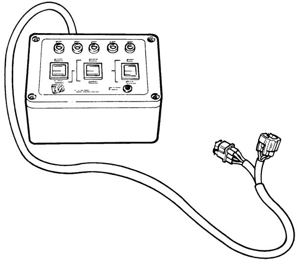
Fig 34. 892/00905 LMI Test Box
Tool Detail Reference
Note: Also requires 721/10885 interconnecting cable
ItemDescription
1Data Link Adaptor (DLA), enables data exchange between the machine ECUs (Electronic Control Units) and laptop PC loaded with the applicable ServiceMaster diagnostics software
2Interconnecting cable, DLA to laptop PC. Several cables are included to enable compatibility with different PC port types
3Kit carrying case
- General Information Service
Section 1
Tools
1-21 1-21 9803/9520-07
Fig 35. 892/01033 Electronic Test Kit
A406130-C1 711300-C1
Fig 36. 892/01096 Speed Sensor Test Harness
Tool Detail Reference 1-22 1-22 9803/9520-07
Section 1 - General Information Service Tools
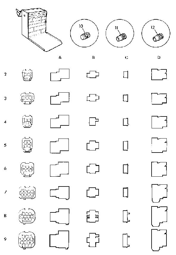
K Electrical Repair Kit ( T 1-22) 1 Electrical Repair Kit 2A 7212/00022 Way Pin Housing 2B 7212/00042 Way Pin Retainer 2C 7212/00032 Way Socket Retainer 2D 7212/00012 Way Socket Connector 3A 7213/00023 Way Pin Housing 3B 7213/00043 Way Pin Retainer 3C 7213/00033 Way Socket Retainer 3D 7213/00013 Way Socket Connector 4A 7213/00063 Way Pin Housing (DT) 4B 7213/00083 Way Pin Retainer (DT) 4C 7213/00073 Way Socket Retainer (DT) 4D 7213/00053 Way Socket Connector (DT) 5A 7214/00024 Way Pin Housing 5B 7214/00044 Way Pin Retainer 5C 7214/00034 Way Socket Retainer 5D 7214/00014 Way Socket Connector 6A 7216/00026 Way Pin Housing 6B 7216/00046 Way Pin Retainer 6C 7216/00036 Way Socket Retainer 6D 7216/00016 Way Socket Connector 7A 7218/00028 Way Pin Housing 7B 7218/00048 Way Pin Retainer 7C 7218/00038 Way Socket Retainer 7D 7218/00018 Way Socket Connector 8A 7219/000210 Way Pin Housing 8B 7219/000410 Way Pin Retainer 8C 7219/000310 Way Socket Retainer 8D 7219/000110 Way Socket Connector 9A 7219/000614 Way Pin Housing 9B 7219/000814 Way Pin Retainer 9C 7219/000714 Way Socket Retainer 9D 7219/000514 Way Socket Connector 10 7210/0001Dummy Plug 11 7210/0002Wire Seal (1.4 - 2.2 mm dia.) 12 7210/0003Wire Seal (2.2 - 2.9 mm dia.)
Fig 37. Electrical Repair Kit
Section E - Hydraulics
Tool Detail Reference
Male Adapters - BSP x BSP
1606/20523/8 in. x 1/4 in.
1604/0003A3/8 in. x 3/8 in.
892/000713/8 in. x 3/8 in. taper
1606/00041/2 in. x 1/4 in.
1606/0007A1/2 in. x 3/8 in.
1604/0004A1/2 in. x 1/2 in.
1606/00175/8 in. x 1/2 in.
1606/00083/4 in. x 3/8 in.
Male Adapters - BSP x NPT (USA only)1606/00093/4 in. x 1/2 in.
816/004393/8 in. x 1/4 in.1604/20553/4 in. x 3/4 in.
816/004401/2 in. x 1/4 in.1606/00123/4 in. x 1 in.
816/15007A3/8 in. x 3/8 in.1606/00143/4 in. x 1.1/4 in.
816/150081/2 in. x 3/8 in.1606/00151 in. x 1.1/4 in.
892/002551/4 in. BSP x Test Point
in. BSP x Test Point
in. BSP x Test Point
in. BSP x Test Point
9803/9520-07
Service
Section 1 - General Information
Tools
1-23 1-23
Fig 38. Male Adaptors
892/002563/8
892/002571/2
892/002585/8
816/151183/4
892/002591
892/002601.1/4 in.
892/002615/8
x Test Point
Fig 39. Pressure Test Adapters
in. BSP x Test Point
in BSP x Test Point
BSP x Test Point
in. UNF
816/550451/4 in. M BSP x 1/4 in. F BSP x Test Point 816/550383/8 in. M BSP x 3/8 in. F BSP x Test Point 816/550401/2 in. M BSP x 1/2 in. F BSP x Test Point 892/002635/8 in. M BSP x 5/8 in. F BSP x Test Point 892/002643/4 in. M BSP x 3/4 in. F BSP x Test Point 892/002651 in. M BSP x 1 in. F BSP x Test Point 892/002661.1/4 in. M BSP x 1.1/4 in. F BSP x Test Point 892/002671.1/4 in. M BSP x 1.1/2 in. F BSP x Test Point
Fig 40. Pressure Test 'T' Adapters
Tool Detail Reference
892/000473/8 in. BSP (A) x 1/4 in. BSP (B)
892/000481/2 in. BSP (A) x 1/4 in. BSP (B)
892/000495/8 in. BSP (A) x 1/4 in. BSP (B)
816/500433/4 in. BSP (A) x 1/4 in. BSP (B)
892/000511 in. BSP (A) x 1/4 in. BSP (B)
816/500051/2 in. BSP (A) x 1/2 in. BSP (B)
816/600963/4 in. BSP (A) x 3/4 in. BSP (B)
816/000171 in. BSP (A) x 1 in. BSP (B)
892/00055A1/4 in. BSP
892/00056A3/8 in. BSP
892/000571/2 in. BSP
892/00058A5/8 in. BSP
892/00059A3/4 in. BSP
892/000601 in. BSP
816/900451/4 in. BSP
816/00189A3/8 in. BSP
816/00190A1/2 in. BSP
816/900225/8 in. BSP
816/902743/4 in. BSP
816/902051 in. BSP
892/000743/8 in. BSP x 3/8 in. BSP
892/000751/2 in. BSP x 1/2 in. BSP
892/000765/8 in. BSP x 5/8 in. BSP
892/000773/4 in. BSP x 3/4 in. BSP
1406/00111/4 in. BSP
1406/00181/2 in. BSP
1406/00145/8 in. BSP
1406/00213/4 in. BSP
1406/00291.1/4 in. BSP
9803/9520-07
Section 1 - General Information Service Tools
1-24 1-24
Fig 41. 'T' Adapters
Fig 42. Female Blanking Caps
Fig 43. Male Cone Blanking Caps
Fig 44. Female Connectors
Fig 45. Bonded Washers
Suggest:
If the above button click is invalid.
Please download this document first, and then click the above link to download the complete manual.
Thank you so much for reading

Detail Reference 1-25 1-25 9803/9520-07
Section 1 - General Information Service Tools Tool
892/01016For
Rod Diameter 892/01017For
Rod Diameter
Rod Diameter 892/01019For
Rod Diameter
50
Rod Diameter (slew ram) 892/01021For 60 mm Rod Diameter 892/01022For 60 mm Rod Diameter (slew ram) 892/01023For 65 mm Rod Diameter 892/01024For 70 mm Rod Diameter 892/01025For 75 mm Rod Diameter 892/01026For 80 mm Rod Diameter 892/00167For 90 mm Rod Diameter
Fig 46. Ram Protection Sleeves
25 mm
30 mm
892/01018For 40 mm
50 mm
892/01020For
mm
Fig 47. 892/00334 Ram Seal Fitting Tool
Caps 992/0930055mm A/F 992/0940065mm A/F 992/0950075mm A/F 992/0960085mm A/F 992/0970095mm A/F 992/09900115mm A/F 992/10000125mm A/F
Fig 48. Hexagon Spanners for Ram Pistons and End
110mm 175mm R1.4mm 3o R3mm 7mm 11o 10mm 20mm 5mm
Fig 49. 892/01027 Piston Seal Assembly Tool