Section 1 - General Information
Section 2 - Care and Safety
Section 3 - Routine Maintenance
Section B - Body and Framework
Section C - Electrics
Section E - Hydraulics


Section F - Transmission
Section G - Brakes
Section H - Steering
Section K - Engine
Section M - Network Systems
Copyright © 2004 JCB SERVICE. All rights reserved. No part of this publication may be reproduced, stored in a retrieval system, or transmitted in any form or by any other means, electronic, mechanical, photocopying or otherwise, without prior permission from JCB SERVICE. World Class Customer Support
9803/9520-06
Issued by JCB Technical Publications, JCB Aftermarket Training, Woodseat, Rocester, Staffordshire, ST14 5BW, England. Tel +44 1889 591300 Fax +44 1889 591400 Service
Publication No.
Manual TM310
Section 0 - Service Manual 0-0 0-0 9803/9520-06
Notes:
Service Manual - TM310
Section 1 - General Information
Section 2 - Care and Safety
Section 3 - Routine Maintenance
Section B - Body and Framework
Section C - Electrics
Section E - Hydraulics
Section F - Transmission
Section G - Brakes
Section H - Steering
Section K - Engine
Section M - Network Systems
Copyright © 2004 JCB SERVICE. All rights reserved. No part of this publication may be reproduced, stored in a retrieval system, or transmitted in any form or by any other means, electronic, mechanical, photocopying or otherwise, without prior permission from JCB SERVICE. World Class Customer Support
Issued by JCB Technical Publications, JCB Aftermarket Training, Woodseat, Rocester, Staffordshire, ST14 5BW, England. Tel +44 1889 591300 Fax +44 1889 591400 Section
9803/9520-03 Publication No.
1 General Information
Section 1 - General Information 1-0 1-0 9803/9520-03
Notes:
Page No. Contents
1 - i 1 - i Introduction About this Publication ...............................................................................1 - 1 Schematic Codes .....................................................................................1 - 2 Colour Codes ......................................................................................1 - 2 Machine Identification Machine Identification Plate ......................................................................1 - 3 Data Plate ............................................................................................1 - 3 Typical Vehicle Identification Number (VIN) ........................................1 - 3 Torque Settings Zinc Plated Fasteners and Dacromet Fasteners ......................................1 - 6 Introduction ..........................................................................................1 - 6 Bolts and Screws .................................................................................1 - 6 Hydraulic Connections ............................................................................1 - 10 'O' Ring Face Seal System ................................................................1 - 10 'Torque Stop' Hose System ...............................................................1 - 13 Service Tools Numerical List .........................................................................................1 - 14 Tool Detail Reference .............................................................................1 - 17 Service Aids Sealing and Retaining Compounds ........................................................1 - 35
Section 1 - General Information
Page No. Contents Section 1 - General Information 1 - ii 1 - ii
Introduction
About this Publication
This publication is designed for the benefit of JCB Distributor Service Engineers who are receiving, or have received, training by JCB Technical Training Department.
These personnel should have a sound knowledge of workshop practice, safety procedures, and general techniques associated with the maintenance and repair of hydraulic earthmoving equipment.
Renewal of oil seals, gaskets, etc., and any component showing obvious signs of wear or damage is expected as a matter of course. It is expected that components will be cleaned and lubricated where appropriate, and that any opened hose or pipe connections will be blanked to prevent excessive loss of hydraulic fluid and ingress of dirt. Finally, please remember above all else SAFETY MUST COME FIRST!
The manual is compiled in sections, the first three are numbered and contain information as follows:
1 General Information - includes torque settings and service tools.
2 Care & Safety - includes warnings and cautions pertinent to aspects of workshop procedures etc.
3 Routine Maintenance - includes service schedules and recommended lubricants for all the machine.
The remaining sections are alphabetically coded and deal with Dismantling, Overhaul etc. of specific components, for example:
A Attachments
B Body and Framework...etc.
Section contents, technical data, circuit descriptions, operation descriptions etc. are inserted at the beginning of each alphabetically coded section. All sections are listed on the front cover.
Where a torque setting is given as a single figure it may be varied by plus or minus 3%. Torque figures indicated are for dry threads, hence for lubricated threads may be reduced by one third.
Section 1 - General Information 1-1 1-1 9803/9520-03
'Left Hand' and 'Right Hand' are as viewed from the rear of the machine facing forwards.
Schematic Codes
Schematic Codes
Colour Codes
The following colour coding, used on illustrations to denote various conditions of oil pressure and flow, is standardised throughout JCB Service Publications.
Red Full Pressure: Pressure generated from operation of a service. Depending on application this may be anything between neutral circuit pressure and MRV operating pressure.
PinkPressure: Pressure that is above neutral circuit pressure but lower than that denoted by Red.
OrangeServo: Oil pressure used in controlling a device (servo).
BlueNeural: Neutral circuit pressure.
GreenExhaust:
Light GreenCavitation: Oil subjected to a partial vacuum due to a drop in pressure (cavitation).
YellowLock Up: Oil trapped within a chamber or line, preventing movement of components (lock up).
Section 1 - General Information Introduction
1-2 1-2
9803/9520-03
Machine Identification
Machine Identification Plate
Data Plate
Your machine has a Data Plate, located as shown at T The serial numbers of the machine, engine and transmission unit are stamped on the plate.
Typical Vehicle Identification Number (VIN)
12345
SLPTM3103E1314700
1 World Manufacturer Identification (SLP = JCB)
2 Machine Type (TM310, TM-W)
3 Year of Manufacture (1 = 2001, 2 = 2002, 3 = 2003, 4 = 2004, 5 = 2005, 6 = 2006, 7 = 2007)
4 Manufacturers Location (E = England)
5 Machine Serial Number (1314700)
Typical Engine Identification Number
T1-005_2
Engine data labels A are located on the cylinder block at position C and rocker cover D (if fitted). K Fig 3. ( T 1-4) The data label contains important engine information and includes the engine identification number E
A typical engine identification number is explained as follows:
SA320/40001U0000104 12345
1 Engine Type
S = 4.4 litre series.
A = Naturally aspirated.
B = Turbocharged.
C = Turbocharged and intercooled.
E = Electronic common rail fuel injection.
2 Engine part number
Section 1 - General Information 1-3 1-3 9803/9520-03
Fig 1.
Fig 2.
A272440
3 Country of manufacture
U = United Kingdom
4 Engine Serial Number
5 Year of Manufacture
The last three parts of the engine identification number are stamped on the cylinder block at position B
U0000104
Machine Identification
Machine Identification Plate
9803/9520-03
Section 1 - General Information
1-4 1-4
Fig 3. Engine
B C D B E
Transmission Identification Numbers
The transmission serial number is stamped on label A which is mounted on the front face.
The drop box serial number is stamped on plate B mounted on the drop box.
The axle serial number is stamped on plate C mounted on the axle
Service Tools
Numerical List
The tools listed in the table are special tools required for carrying out the procedures described in this manual. These tools are available from JCB Service or, in some instances, can be manufactured locally from the specifications given in this section.
Some tools are supplied as kits or sets. Cross references are given to tables showing the kit contents.
Note: Tools other than those listed will be required. It is expected that such general tools will be available in any well equipped workshop or be available locally from any good tool supplier.
Section 1 - General Information 1-14 1-14 9803/9520-03
Part Number: Description:Tool Detail Reference: -AVO Test Kit - see tool detail reference for content K Fig 27. ( T 1-21) -Bonded Washers - see tool detail reference for content K Fig 41. ( T 1-26) -Electrical Repair Kit - see tool detail reference for content K Fig 30. ( T 1-22) -Engine and Transmission Lifting Frame K Fig 61. ( T 1-34) -Female Cone Blanking Plugs - see tool detail reference for content K Fig 42. ( T 1-26) -Female Connectors - see tool detail reference for content K Fig 45. ( T 1-27) -Hydraulic Hand Pump Equipment - see tool detail reference for content K Fig 46. ( T 1-27) -Male Adaptors BSP x BSP - see tool detail reference for content K Fig 40. ( T 1-26) -Male Adaptors BSP x NPT (USA only) - see tool detail reference for content K Fig 40. ( T 1-26) -Male Cone Blanking Caps - see tool detail reference for content K Fig 44. ( T 1-26) -Pressure Test Point `T' Adaptors - see tool detail reference for content K Fig 36. ( T 1-25) -Pressure Test Point Adaptors - see tool detail reference for content K Fig 37. ( T 1-25) -Rivet Nut Tool - see tool detail reference for content K Fig 10. ( T 1-17) 320/20050Engine Lifting Bracket Kit K Fig 60. ( T 1-33) 460/15708Flow Test Adaptor (Powershift) - Other components required, see tool detail K Fig 47. ( T 1-28) 721/10885Interconnecting Cable - use with 892/01033 K Fig 32. ( T 1-23) 892/00011Spool Clamp K Fig 53. ( T 1-30) 892/00167Ram Protection Sleeve for 90 mm Rod Diameter K Fig 52. ( T 1-29) 892/00180Seal Fitting Tool - Hydraulic Steer Unit K Fig 55. ( T 1-30) 892/00181Replacement Plastic Boss for 892/00180 K Fig 55. ( T 1-30) 892/00253Hydraulic Pressure Test Kit - see tool detail reference for content K Fig 35. ( T 1-24) 892/00268Flow Monitoring Unit - Other components required, see tool detail K Fig 34. ( T 1-24) 892/00334Ram Seal Fitting Tool K Fig 51. ( T 1-29) 892/00812Drive Coupling Spanner K Fig 58. ( T 1-31) 892/00822Splined Bolt Socket K Fig 57. ( T 1-31) 892/00842Glass Lifter K Fig 13. ( T 1-18)
Numerical List 1-15 1-15 9803/9520-03 892/00843Folding Stand for Holding Glass K Fig 14. ( T 1-18) 892/00844Long Knife K Fig 15. ( T 1-18) 892/00845Cartridge Gun K Fig 16. ( T 1-18) 892/00846Glass Extractor (Handles) K Fig 17. ( T 1-18) 892/00847Nylon Spatula K Fig 18. ( T 1-19) 892/00848Wire Starter K Fig 19. ( T 1-19) 892/00849Braided Cutting Wire K Fig 20. ( T 1-19) 892/00881Valve Spool Seal Fitting Tool K Fig 54. ( T 1-30) 892/00905LMI Test Box K Fig 29. ( T 1-21) 892/00913Grease gun attachment - Use where access to the grease nipple is restricted E.g. Axle driveshaft universal joints K Fig 12. ( T 1-18) 892/00948Nitrogen Charging Kit (without gauge) K Fig 48. ( T 1-28) 892/00949Gauge K Fig 48. ( T 1-28) 892/00964 Test Point 1/8 BSP (Powershift) K Fig 38. ( T 1-25) 892/00965 Test Point 3/8 BSP (Powershift) K Fig 39. ( T 1-25) 892/01016Ram Protection Sleeve for 25 mm Rod Diameter K Fig 52. ( T 1-29) 892/01017Ram Protection Sleeve for 30 mm Rod Diameter K Fig 52. ( T 1-29) 892/01018Ram Protection Sleeve for 40 mm Rod Diameter K Fig 52. ( T 1-29) 892/01019Ram Protection Sleeve for 50 mm Rod Diameter K Fig 52. ( T 1-29) 892/01020Ram Protection Sleeve for 50 mm Rod Diameter K Fig 52. ( T 1-29) 892/01021Ram Protection Sleeve for 60 mm Rod Diameter K Fig 52. ( T 1-29) 892/01022Ram Protection Sleeve for 60 mm Rod Diameter K Fig 52. ( T 1-29) 892/01023Ram Protection Sleeve for 65 mm Rod Diameter K Fig 52. ( T 1-29) 892/01024Ram Protection Sleeve for 70 mm Rod Diameter K Fig 52. ( T 1-29) 892/01025Ram Protection Sleeve for 75 mm Rod Diameter K Fig 52. ( T 1-29) 892/01026Ram Protection Sleeve for 80 mm Rod Diameter K Fig 52. ( T 1-29) 892/01027Piston Seal Assembly Tool K Fig 50. ( T 1-29) 892/01033Electronic Service Tool Kit - also requires 721/10885 K Fig 31. ( T 1-23) 892/01096Speed Sensor Test Harness (Powershift) K Fig 33. ( T 1-23) 892/01110Torque Converter Alignment Tool K Fig 59. ( T 1-32) 926/15500Rubber Spacer Blocks K Fig 21. ( T 1-19) 992/04000Torque Multiplier K Fig 56. ( T 1-31) 992/09100Spool Clamp K Fig 53. ( T 1-30) 992/09300Hexagon Spanner 55 mm A/F K Fig 49. ( T 1-29) 992/09400Hexagon Spanner 65 mm A/F K Fig 49. ( T 1-29) 992/09500Hexagon Spanner 75 mm A/F K Fig 49. ( T 1-29) 992/09600Hexagon Spanner 85 mm A/F K Fig 49. ( T 1-29) Part Number: Description:Tool Detail Reference:
Section 1 - General Information Service Tools
Numerical List 1-16 1-16 9803/9520-03 992/09700Hexagon Spanner 95 mm A/F K Fig 49. ( T 1-29) 992/09800Hexagon Spanner 105 mm A/F K Fig 49. ( T 1-29) 992/09900Hexagon Spanner 115 mm A/F K Fig 49. ( T 1-29) 992/10000Hexagon Spanner 125 mm A/F K Fig 49. ( T 1-29) 992/1230012V Mobile Oven K Fig 22. ( T 1-19) 992/1240024V Static Oven (2 Cartridge) K Fig 23. ( T 1-19) 992/1260024V Static Oven (6 Cartridge) K Fig 23. ( T 1-19) 992/12800Cut-Out Knife K Fig 24. ( T 1-20) 992/12801`L' Blades K Fig 25. ( T 1-20) 993/68100Slide Hammer Kit - see tool detail reference for content K Fig 11. ( T 1-17) 993/85700Battery Tester K Fig 28. ( T 1-21) 4104/1310Hand Cleaner K Fig 26. ( T 1-20) Part Number: Description:Tool Detail Reference:
Section 1 - General Information Service Tools
Tool Detail Reference
Tool Detail Reference
826/01099M6 x 16 mm Rivet Nut
826/01101M6 x 19 mm Rivet Nut
826/01102M8 x 18 mm Rivet Nut
826/01103M8 x 21 mm Rivet Nut
826/01104M10 x 23 mm Rivet Nut
826/01105M10 x 26 mm Rivet Nut
Installation Tool Available from:
Section 1 - General Information Service Tools
1-17 1-17 9803/9520-03
Fig 10. Rivet Nut Tool
Bollhoff Fastenings Ltd. Midacre The Willenhall Estate Rose Hill Willenhall West Midlands, WV13 2JW 1 993/68101 Slide Hammer 6 993/68106 Adaptor - M20 x M24 2 993/68102 End Stops 7 993/68107 Bar - M20 x M20 X 800 mm 3 993/68103 Adaptor - M20 x 5/8" UNF 8 993/68108 Adaptor - M20 x 7/8" UNF 4 993/68104 Adaptor - M20 x 1" UNF 9 993/68109 Adaptor - M20 x M12 5 993/68105 Adaptor - M20 x M20 10 993/68110 Adaptor - M20 x M16 (Shoulder) 11 993/68111 Adaptor - M20 x 1/2" UNF
Fig 11. 993/68100 Slide Hammer Kit
Used
Tool Detail Reference
Minimum
Hand operated. Essential for the application of
Used
1 - General Information Service Tools
Section
1-18 1-18 9803/9520-03
Fig 12. 892/00913 Grease Gun Attachment
Fig 13. 892/00842 Glass Lifter
2 off - Essential for glass installation, 2 required to handle large panes of glass. Ensure suction cups are protected from damage during storage.
Fig 14. 892/00843 Folding Stand Essential for preparing new glass prior to installation.
Fig 15. 892/00844 Long Knife
to give extended reach for normally inaccessible areas.
Fig 16. 892/00845 Cartridge Gun
sealants, polyurethane materials etc.
Fig 17. 892/00846 Glass Extractor (Handles)
with braided cutting wire K Fig 20. ( T 1-19) to cut out broken glass.
Used
Tool Detail Reference
1 cartridge capacity. Required to pre-heat adhesive prior to use. It is fitted with a male plug (703/23201) which fits into a female socket (715/04300).
Available with 2 or 6 cartridge capacity. Required to preheat adhesive prior to use. No plug supplied. Note: 110V models available upon request - contact JCB Technical Service.
1 - General Information Service Tools
Section
1-19 1-19
9803/9520-03
Fig 18. 892/00847 Nylon Spatula General tool used for smoothing sealants - also used to reinstall glass in rubber glazing because metal tools will chip the glass edge.
Fig 19. 892/00848 Wire Starter Used to access braided cutting wire K Fig 20. ( T 1-19) through original polyurethane seal.
Fig 20. 892/00849 Braided Cutting Wire Consumable heavy duty cut-out wire used with the glass extraction tool K Fig 17. ( T 1-18), approx. 25 m length.
Fig 21. 926/15500 Rubber Spacer Blocks
to provide the correct set clearance between glass edge and cab frame. Unit quantity = 500 off.
Fig 22. 992/12300 Mobile Oven 12V
Fig 23. 992/12400, 992/12600 Static Oven 240V
Tool Detail Reference
Section 1 - General Information Service Tools
1-20 1-20
9803/9520-03
Fig 24. 992/12800 Cut-Out Knife Used to remove broken glass
Fig 25. 992/12801 `L' Blades 25 mm (1 in) cut. Replacement blades for cut-out knife K Fig 24. ( T 1-20). Unit quantity = 5 off.
Fig 26. 4104/1310 Hand Cleaner Special blend for the removal of polyurethane adhesives (454g; 1 lb tub).
Tool Detail Reference
AVO Test Kit:
1 892/00283 Tool Kit Case
2 892/00298 Fluke Meter 85
3 892/00286 Surface Temperature Probe
4 892/00284 Venture Microtach Digital Tachometer
5 892/00282 100 amp Shunt - open type
6 892/00285 Hydraulic Temperature Probe
9803/9520-03
Section 1 - General Information Service Tools
1-21 1-21
Fig 27. AVO Test Kit
Fig 28. 993/85700 Battery Tester
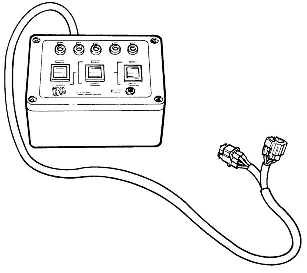
Fig 29. 892/00905 LMI Test Box For testing load moment indicator system
Tool Detail Reference 1-22 1-22 9803/9520-03
Section 1 - General Information Service Tools
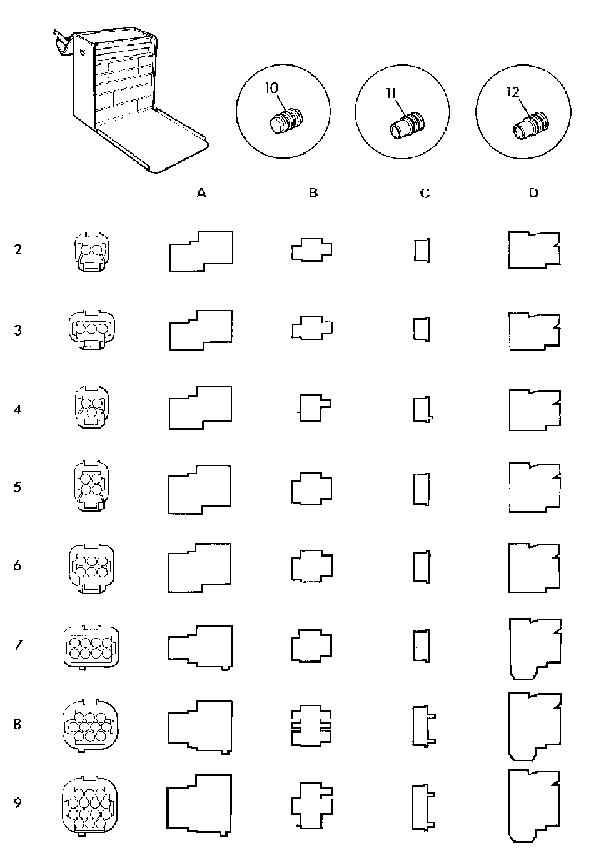
K Electrical Repair Kit ( T 1-22) 1 Electrical Repair Kit 2A 7212/00022 Way Pin Housing 2B 7212/00042 Way Pin Retainer 2C 7212/00032 Way Socket Retainer 2D 7212/00012 Way Socket Connector 3A 7213/00023 Way Pin Housing 3B 7213/00043 Way Pin Retainer 3C 7213/00033 Way Socket Retainer 3D 7213/00013 Way Socket Connector 4A 7213/00063 Way Pin Housing (DT) 4B 7213/00083 Way Pin Retainer (DT) 4C 7213/00073 Way Socket Retainer (DT) 4D 7213/00053 Way Socket Connector (DT) 5A 7214/00024 Way Pin Housing 5B 7214/00044 Way Pin Retainer 5C 7214/00034 Way Socket Retainer 5D 7214/00014 Way Socket Connector 6A 7216/00026 Way Pin Housing 6B 7216/00046 Way Pin Retainer 6C 7216/00036 Way Socket Retainer 6D 7216/00016 Way Socket Connector 7A 7218/00028 Way Pin Housing 7B 7218/00048 Way Pin Retainer 7C 7218/00038 Way Socket Retainer 7D 7218/00018 Way Socket Connector 8A 7219/000210 Way Pin Housing 8B 7219/000410 Way Pin Retainer 8C 7219/000310 Way Socket Retainer 8D 7219/000110 Way Socket Connector 9A 7219/000614 Way Pin Housing 9B 7219/000814 Way Pin Retainer 9C 7219/000714 Way Socket Retainer 9D 7219/000514 Way Socket Connector 10 7210/0001Dummy Plug 11 7210/0002Wire Seal (1.4 - 2.2 mm dia.) 12 7210/0003Wire Seal (2.2 - 2.9 mm dia.)
Fig 30. Electrical Repair Kit
Note: Also requires 721/10885 interconnecting cable
ItemDescription
1Data Link Adaptor (DLA), enables data exchange between the machine ECUs (Electronic Control Units) and laptop PC loaded with the applicable ServiceMaster diagnostics software
2Interconnecting cable, DLA to laptop PC. Several cables are included to enable compatibility with different PC port types
3Kit carrying case
- General Information Service
1-23 1-23 9803/9520-03
Section 1
Tools Tool Detail Reference
Fig 31. 892/01033 Electronic Test Kit
A406130-C1 A406130-C2 D F A B H J E G
Fig 32. 721/10885 Interconnecting Cable Use with 892/01033
711300-C1
Fig 33. 892/01096 Speed Sensor Test Harness
Note: Components listed as follows also required
1406/0021Sealing washer
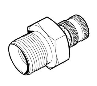
1604/0006 Adaptor 3/4 in M x 3/4 in M BSP
1604/0008Adaptor 1 in M x 1 in M BSP
1606/0012 Adaptor 1 in M x 3/4 in M BSP
1606/0015 Adaptor 11/4 in M x 1 in M BSP
1612/0006 Adaptor 3/4 in F x 3/4 in M BSP
816/20008 Adaptor 3/4in F x 1/2 in M BSP
816/20013 Adaptor 3/4 in F x 1 in M BSP
892/00078Connector 1 in F x 1 in F BSP
892/00269Sensor head 0 - 100 l /min. (0 - 22 UK gal / min.)
892/00270Load valve
892/00271 Adaptor 3/4 in F x 5/8 in M BSP
892/00272 Adaptor 5/8 in F x 3/4 in M BSP
892/00273Sensor head 0 - 380 l per min.
892/00275 Adaptor 1/2 in F x 3/4 in M BSP
892/00276 Adaptor 3/4 in F x 3/8 in M BSP
892/00277 Adaptor 3/8 in F x 3/4 in M BSP
892/00293Connector pipe
892/00294Connector pipe
Tool Detail Reference
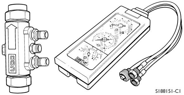
ItemDescription
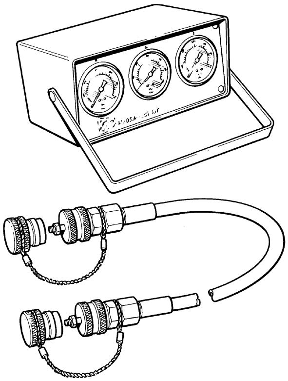
1892/00201 Replacement gauge 0 -20 bar (0-300 lbf/in2
2892/00202 Replacement gauge 0 -40 bar (0-600 lbf/in2
3892/00203 Replacement gauge 0 -400 bar (06000 lbf/in2
4892/00254 Replacement hose
Note: Components listed as follows also required 993/69800 Seal kit for 892/00254 (can also be used with probe 892/00706)
892/00706 Test probe
892/00347 Connector - hose to gauge
Section 1 - General Information Service Tools
1-24 1-24
9803/9520-03
Fig 34. 892/00268 Flow Monitoring Unit
Fig 35. 892/00253 Hydraulic Pressure Test Kit
892/002621/4 in M BSP x 1/4 in F BSP x Test Point
816/550383/8 in M BSP x 3/8 in F BSP x Test Point
816/550401/2 in M BSP x 1/2 in F BSP x Test Point
892/002635/8 in M BSP x 5/8 in F BSP x Test Point
892/002643/4 in M BSP x 3/4 in F BSP x Test Point
892/002651 in M BSP x 1 in F BSP x Test Point
892/002551/4 in BSP x Test Point
892/002563/8 in BSP x Test Point
892/002571/2 in BSP x Test Point
892/002585/8 in BSP x Test Point
816/151183/4 in BSP x Test Point
892/002591 in BSP x Test Point
892/002601.1/4 in BSP x Test Point
892/002615/8 in UNF x Test Point
Tool Detail Reference
- General Information Service
Section 1
Tools
1-25 1-25
9803/9520-03
Fig 36. Pressure Test `T' Adaptors
Fig 37. Pressure Test Adaptors
Fig 38. 892/00964 Test Point 1/8 BSP
Fig 39. 892/00965 Test Point 3/8 BSP
Male Adapters - BSP x NPT (USA only)
816/004393/8 in. x 1/4 in.
816/004401/2 in. x 1/4 in.
816/150073/8 in. x 3/8 in.
816/150081/2 in. x 3/8 in.
Male Adapters - BSP x BSP
1606/00033/8 in. x 1/4 in.
1604/00033/8 in. x 3/8 in.
892/000713/8 in. x 3/8 in. taper
1606/00041/2 in. x 1/4 in.
1606/00071/2 in. x 3/8 in.
1604/00041/2 in. x 1/2 in.
1606/00175/8 in. x 1/2 in.
1606/00083/4 in. x 3/8 in.
1606/00093/4 in. x 1/2 in.
1604/00063/4 in. x 3/4 in.
1606/00123/4 in. x 1 in.
1606/00143/4 in. x 1.1/4 in.
1606/00151 in. x 1.1/4 in.
892/000551/4 in. BSP
892/000563/8 in. BSP
892/000571/2 in. BSP
892/000585/8 in. BSP
892/000593/4 in. BSP
892/000601 in. BSP
Tool Detail Reference
1406/00111/4 in. BSP
1406/00181/2 in. BSP
1406/00145/8 in. BSP
1406/00213/4 in. BSP
1406/00291.1/4 in. BSP
892/000473/8 in. BSP (A) x 1/4 in. BSP (B)
892/000481/2 in. BSP (A) x 1/4 in. BSP (B)
892/000495/8 in. BSP (A) x 1/4 in. BSP (B)
816/500433/4 in. BSP (A) x 1/4 in. BSP (B)
892/000511 in. BSP (A) x 1/4 in. BSP (B)
816/500051/2 in. BSP (A) x 1/2 in. BSP (B)
816/600963/4 in. BSP (A) x 3/4 in. BSP (B)
816/000171 in. BSP (A) x 1 in. BSP (B)
816/002941/4 in. BSP
816/001893/8 in. BSP
816/001901/2 in. BSP
816/001975/8 in. BSP
816/001963/4 in. BSP
816/001931 in. BSP
- General Information Service
Section 1
Tools
1-26 1-26
9803/9520-03
Fig 40. Male Adaptors
Fig 41. Bonded Washers
Fig 42. Female Blanking Caps
Fig 43. T Adaptors
Fig 44. Male Cone Blanking Caps
Tool Detail Reference
892/000743/8 in. BSP x 3/8 in. BSP
892/000751/2 in. BSP x 1/2 in. BSP
892/000765/8 in. BSP x 5/8 in. BSP
892/000773/4 in. BSP x 3/4 in. BSP
892/00223Hand Pump
892/00137Micro-bore Hose 1/4 in BSP x 3 metres
892/00274Adapter 1/4 in M BSP x 3/8 in M BSP Taper
892/002621/4 in M BSP x 1/4 in F BSP x Test Point
892/00706Test Probe
892/00278 Gauge 0 - 40 bar (0 - 600 lbf/in2)
892/00279 Gauge 0 - 400 bar (0 - 6000 lbf/in2)
Section 1 - General Information Service Tools
1-27 1-27
9803/9520-03
Fig 45. Female Connectors
Fig 46. Hand Pump Equipment
Note: Components listed below also required
- General Information Service Tools Tool Detail Reference 1-28 1-28 9803/9520-03
Section 1
Fig 47. 460/15708 Flow Test Adaptor
ItemDescription 1460/15707 Banjo bolt 22401/0222 O-ring 32403/0110 O-ring 42403/0108 O-ring 51604/0004 Adaptor - 2 off 61406/0018 Sealing washer - 2 off A313250-C1 1 3 4 2 6 5
Fig 48. Nitrogen Charging Kit
892/00948Charging
Kit (without gauge)
892/00949Gauge
Tool Detail Reference
992/0930055 mm A/F
992/0940065 mm A/F
992/0950075 mm A/F
992/0960085 mm A/F
992/0970095 mm A/F
992/09800105 mm A/F
992/09900115 mm A/F
992/10000125 mm A/F
892/01016For 25 mm Rod Diameter
892/01017For 30 mm Rod Diameter
892/01018For 40 mm Rod Diameter
892/01019For 50 mm Rod Diameter
892/01020For 50 mm Rod Diameter (slew ram)
892/01021For 60 mm Rod Diameter
892/01022For 60 mm Rod Diameter (slew ram)
892/01023For 65 mm Rod Diameter
892/01024For 70 mm Rod Diameter
892/01025For 75 mm Rod Diameter
892/01026For 80 mm Rod Diameter
892/00167For 90 mm Rod Diameter
General Information
Section 1 -
Service Tools
1-29 1-29
9803/9520-03
Fig 49. Hexagon Spanners for Ram Pistons and End Caps
110mm 175mm R1.4mm 3o R3mm 7mm 11o 10mm 20mm 5mm
Fig 50. 892/01027 Piston Seal Assembly Tool
Fig 51. 892/00334 Ram Seal Fitting Tool
Fig 52. Ram Protection Sleeves
Tool Detail Reference
1 - General Information Service
Section
Tools
1-30 1-30
9803/9520-03
Fig 53. Spool Clamps
992/09100Spool Clamp
892/00011Spool Clamp
Fig 54. 892/00881 Valve Spool Seal Fitting Tool
Fig 55.
892/00180Seal Fitting Tool for fitting 'O' ring and kin ring to Hydraulic Steer Unit
892/00181Replacement plastic boss
Tool Detail Reference
1 - General Information Service Tools
Section
1-31 1-31 9803/9520-03
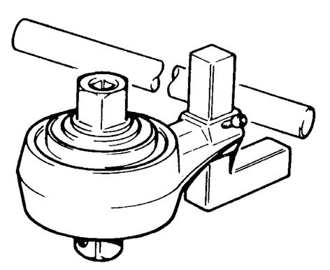
Fig 56. 992/04000 Torque Multiplier
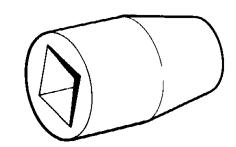
Fig 57. 892/00822 Splined Bolt Socket
Fig 58. 892/00812 Drive Coupling Spanner
1 - General Information Service Tools Tool Detail Reference 1-32 1-32 9803/9520-03
Section
A A SECTION A-A 30.2 30.1 43.4 43.3 57.0 REF 2 DOWELS 8.0 12.0 10.0 TYP 10.0 TYP 10.0 x 45 TYP 1.0 65.0 171.0 185.0 342.0 370.0 0.3 X 2 DOWELS 8 x 32 LONG PRESS FIT 0.3 X 5 3 x 35(25) X A436700
Fig 59. 892/01110 Torque Converter Alignment Tool For use with 12" and W300 torque converters
Suggest:
If the above button click is invalid.
Please download this document first, and then click the above link to download the complete manual.
Thank you so much for reading

Tool Detail Reference
Note: Brackets are designed to lift only the engine. They MUST NOT be used to lift the engine and transmission
- General Information Service
Section 1
Tools
1-33 1-33
9803/9520-03
Fig 60. 320/20050 Engine Lifting Bracket Kit
assembly.