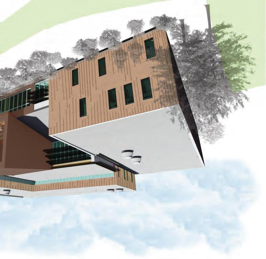
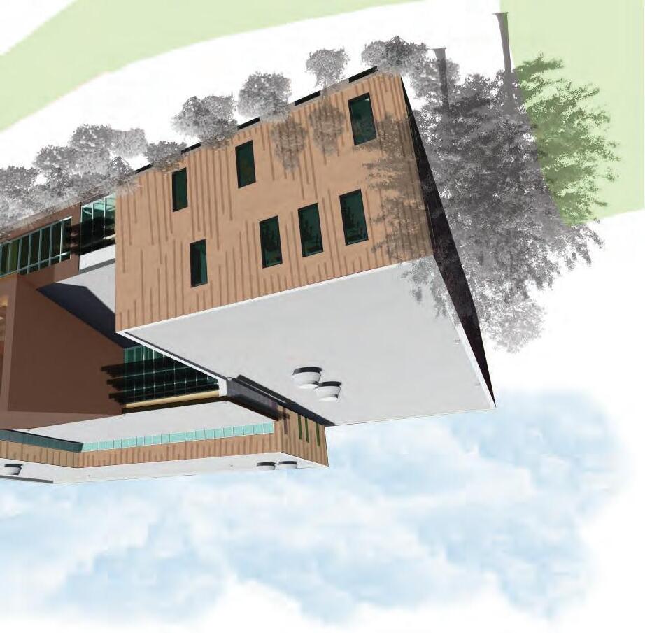
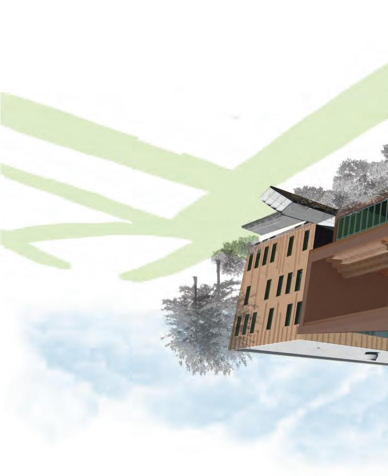
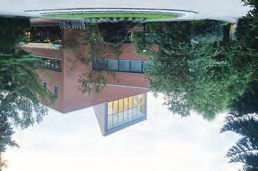
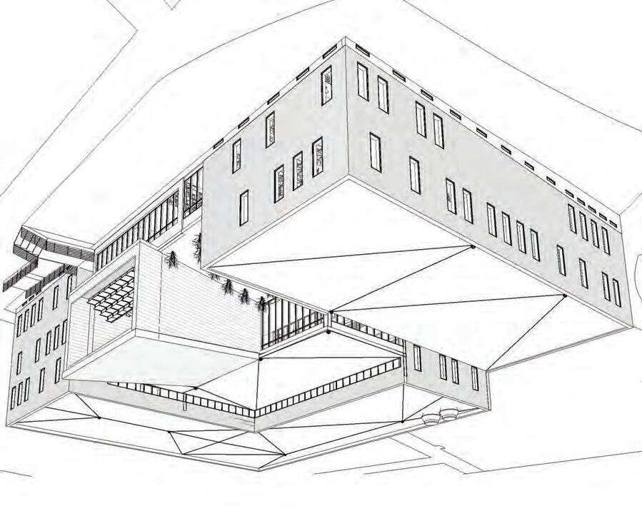
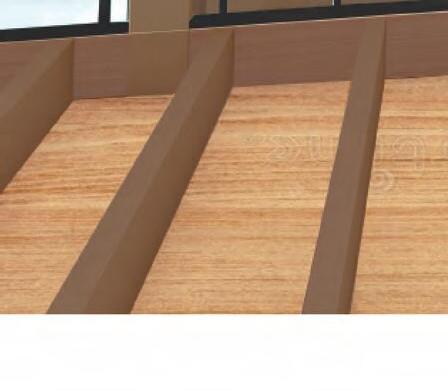
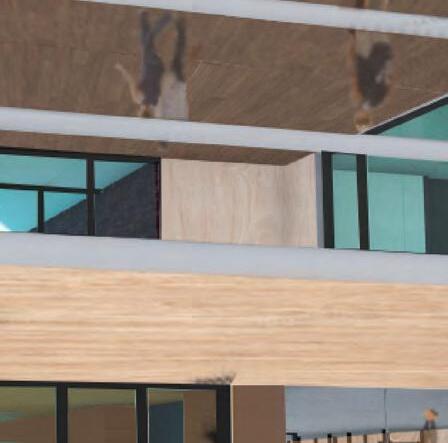
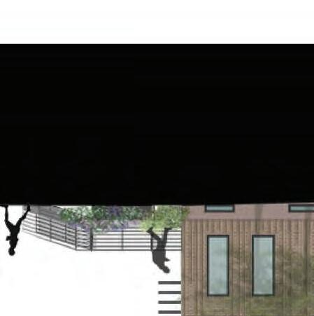
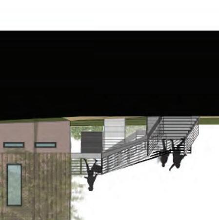
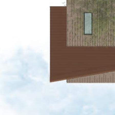
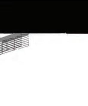
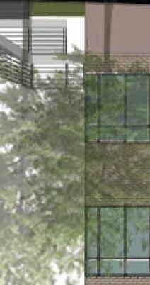
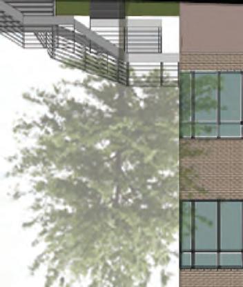
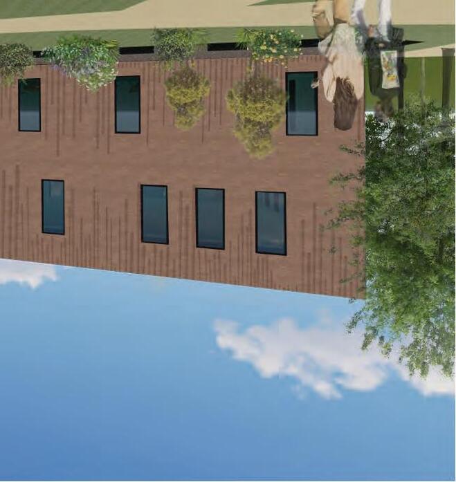
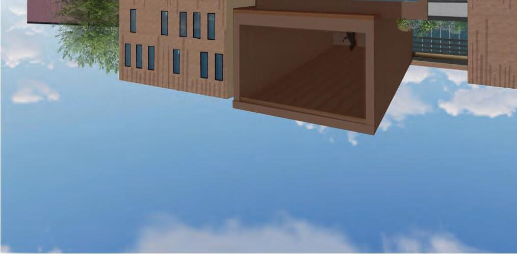
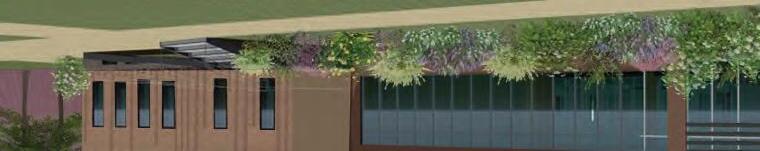
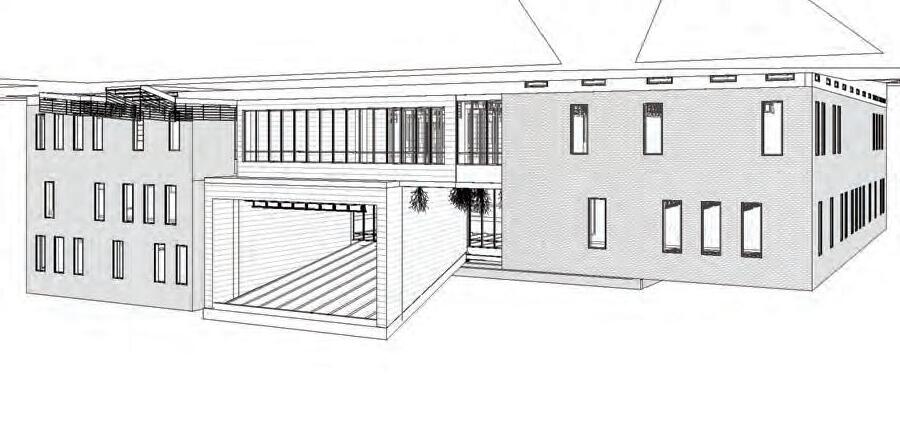
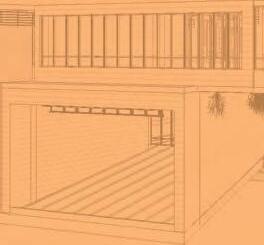
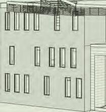
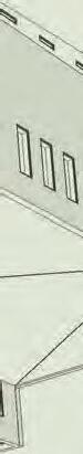
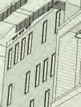
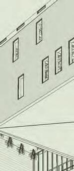
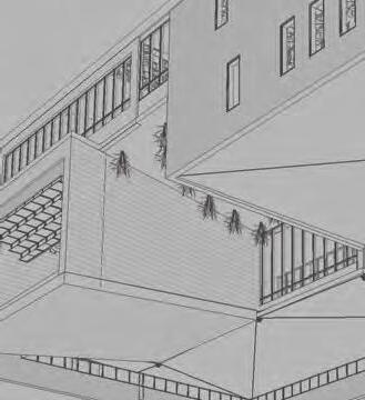
SOUTHEAST PERSPECTIVE


DESIGN TAKEAWAYS


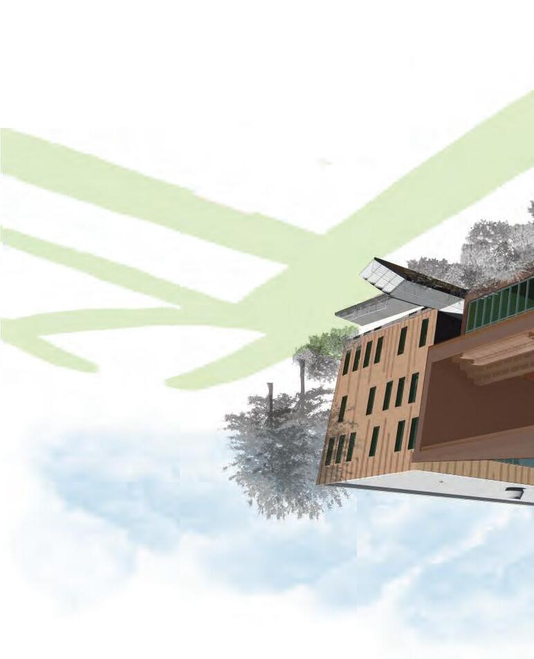
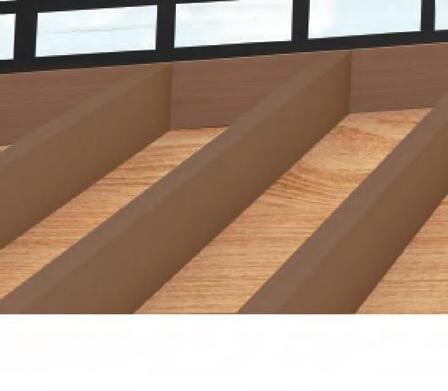
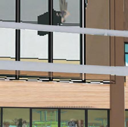
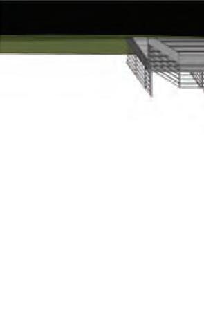
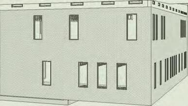
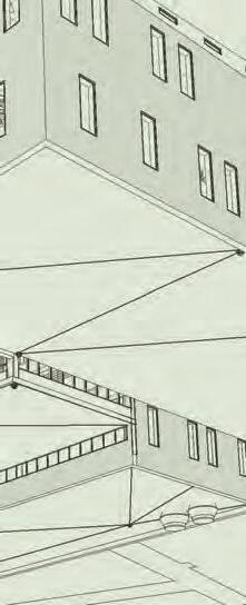
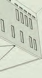
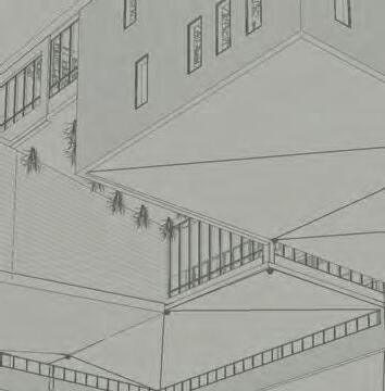
NORTHEAST PERSPECTIVE


PROGRAMMATIC BREAKDOWN


SCALE: 1/64”= 1’-0”
SCALE: 1/64”= 1’-0”
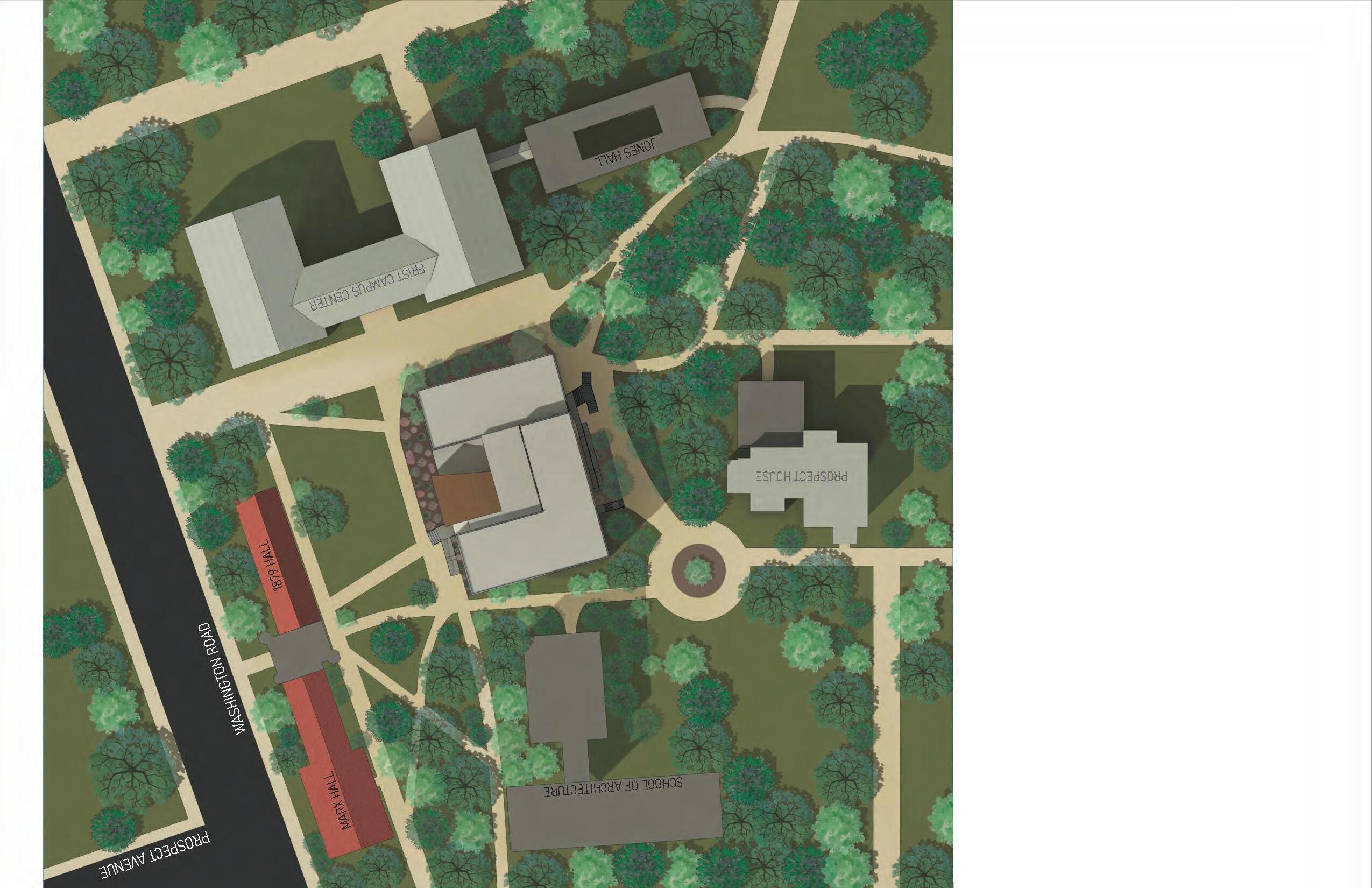
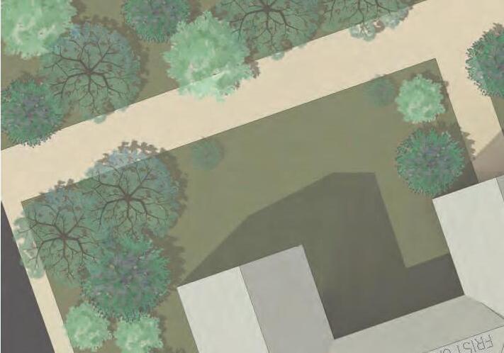
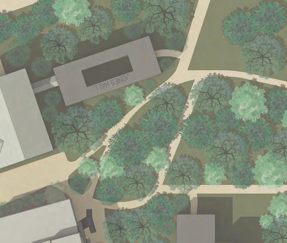
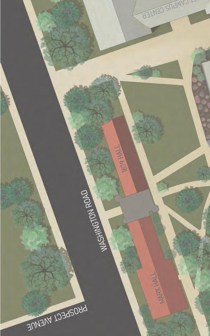
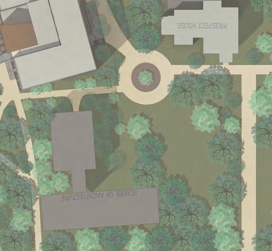
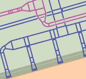
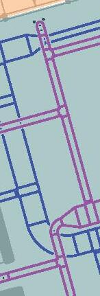
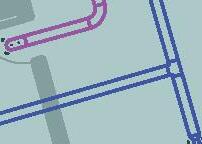
SITE CIRCULATION
DIRECT AND INDIRECT SUNLIGHT ATRIUM SUNLIGHT AND NATURAL VENTILATION


ZONING USE DESIGNATION
E2
ALLOWABLE HEIGHT
ALLOWABLE STORIES
BUILDING USE CLASSIFICATION: B (Business) with automatic sprinkler system and an emergency voice/alarm communication system
TOTAL NUMBER OF ALLOWABLE OCCUPANTS:
*Basement = 213 Persons
*First Floor = 514 Persons
*Second Floor = 500 Persons
*Third Floor = 145 Persons
*Total = 1372 Persons
***Original Woolworth Center Total = 1316 Persons
OCCUPANCY CALCULATIONS
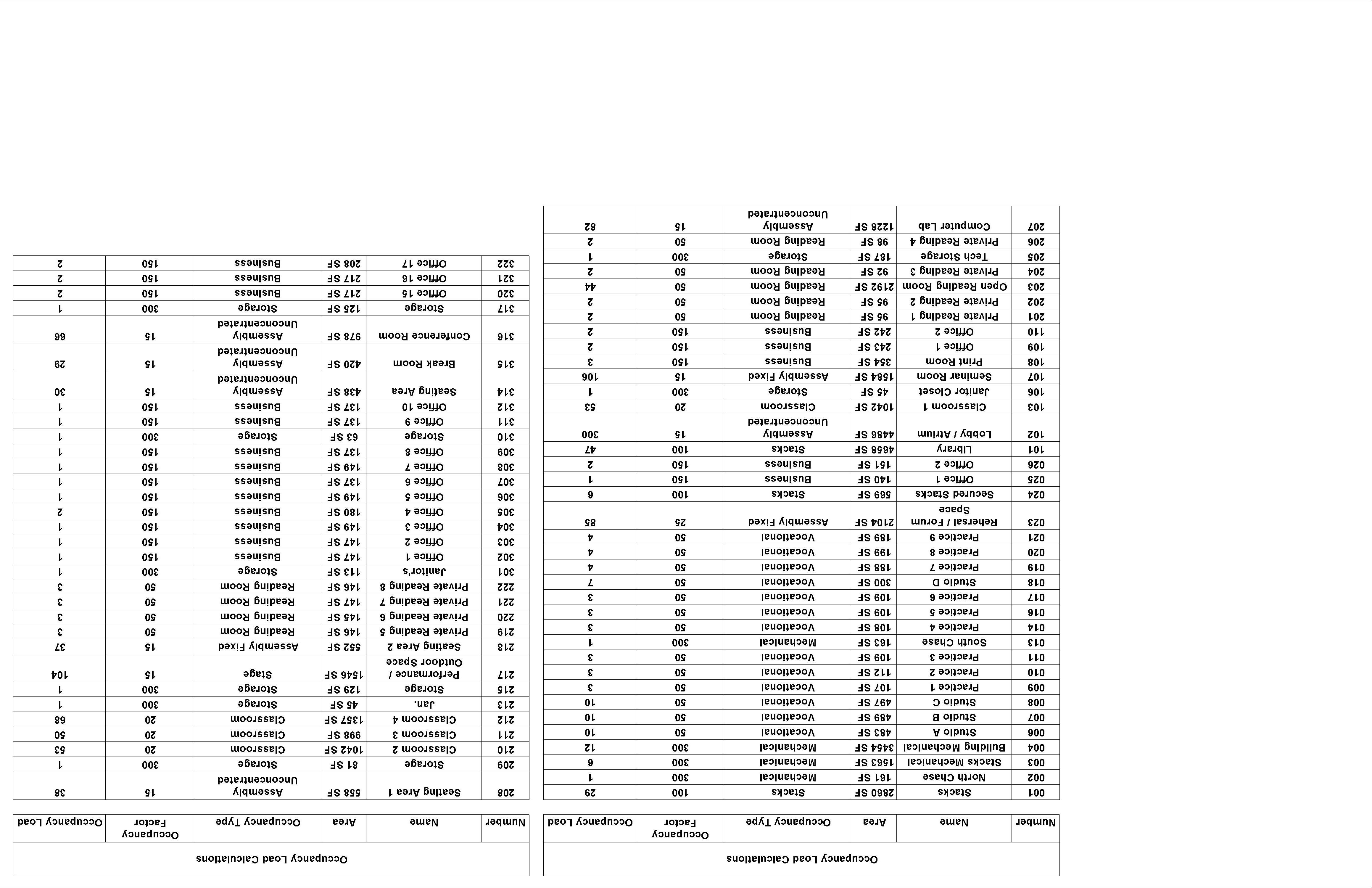
ALLOWABLE OCCUPANCY CALCULATION BREAKDOWN: IBC 2018, TABLE 1004.5
*Stacks/Library/Secured Stacks - “Stacks” = 100 gross sqft per occupant
*Faculty/Student Offices/Print Room - “Business” = 150 gross sqft per occupant
*Mechanical/Vertical Chases - “Mechanical” = 300 gross sqft per occupant
*Practice Room/Studio Space = “Vocational” = 50 net sqft per occupant
*Rehersal Space/Seminar Room - “Assembly Fixed” = 1 fixed seat per occupant
*Lobby/Seating Area/Computer Lab/Break Room/Conference Room“Assembly Unconcentrated” = 15 net sqft per occupant
*Classrooms - “Classroom” = 20 net sqft per occupant
*Storage Room/Janitor Closet/Tech Storage - “Storage” = 300 gross sqft per occupant
*Open Reading Room/Private Reading Room - “Reading Room” = 50 net sqft per occupant
*Performance Space - “Stage” = 15 net sqft per occupant
*Restrooms/stairs/corridors - does not classify as occupiable spaces
MINIMUM NUMBER OF EXITS OR ACCESS TO EXITS PER STORY:
IBC 2018 table 1006.3.2
*Basement = 2 exit staircases
*First Floor = 3 exits
*Second Floor = 2 exit staircases
*Third Floor = 2 exit staircases
IBC 2018 section 1007.1.1, exception 2
*Distance between two exits, exit access doorways, or ramps, shall be placed no more than 1/3 of the maximum overall diagonal length apart from another.
*Overall diagonal length = 199’-10 1/2”
*Distance between means of egress = 199’-10 1/2“ x 0.333 = 65’-5 1/2”
EGRESS STAIR REQUIREMENTS:
IBC 2018 section 1005.3.1, exception 1
*Width = multiply the occupant load by the capacity factor of 0.2”
*Widths meeting requirements shall be dimensioned in plan
IBC 2018 section 1011.5.2
*Stair riser heights = 7” maximum and 4“ minimum
*Stair treads = 11” minimum in depth
*Per IBC 2018 section 1011.5.4, stair treads and risers should be uniform in shape and size
IBC 2018 section 1014.1
*Handrails = must be on both sides of stairway
* Handrail height = 34“ minimum, measured above stair tread nosings with a 38” maximum
IBC 2018 1009.3.3
*Area of refuge is not required in an automatic sprinkler system building per 2
EGRESS EXIT REQUIREMENTS:
IBC 2018 section 1005.3.2, exception 1
*Width = multiply the occupant load that will be utilizing the specific exit by 0.15”
*Widths of egress exits meeting requirements shall be dimensioned in plan
IBC 2018 section 1010.1.2
*Door swings = pivoted or side-hinged and must swing in the direction of egress travel
IBC 2018 table 1020.1
*Corridor fire resistance rating = not required for a building with sprinkler system
IBC 2018 section 1003.3
*Clearance = minimum headoom of 80” over any circulation paths for egress
ACCOMMODATIONS FOR ACCESSIBLE MEANS OF EGRESS:
IBC 2018 section 1009.1
*Required accessible means = no less than one accessible means of egress in a building
IBC 2018 section 1009.3
*Stairways = clear width of 48” minimum is not required for a building with sprinkler system, per exception 2
IBC 2018 section 1009.4
*Elevators = 4 or more stories above or below a level of exit discharge, a minimum of 1 accessible elevator must be provided and equipped with standby emergency power
MAXIMUM PATH OF TRAVEL:
IBC 2018 table 1017.2
Maximum travel distance for B (Business) occupancy = 300 feet
FIRST FLOOR EGRESS DOOR REQUIREMENTS AND CALCULATIONS
IBC 2018 section 1006.3.2, exception 1
*Number of doors required = 3
*Width - occupant load served by door as a means of egress x 0.15”
Door 1 = 36 occupants x 0.15” = 5.4“ ”
Door 2 = 57 occupants x 0.15” = 8.55”
Door 3 = 228 occupants x 0.15“ = 34.2” = 2’-10 2/3“
Door 4 = 539 occupants x 0.15” = 80.85” = 6’-8 7/8”
Door 5 = 509 occupants x 0.15” = 76.35” = 6’ 4 3/8”
BUILDING EGRESS STAIR REQUIREMENTS AND CALCULATIONS:
IBC 2018 section 1005.3.1, exception 1
*Width - floor’s occupancy load x 0.2 with an absolute minimum of 44“
*Third floor stair widths = 145 occupants x 0.2” = 29“ = absolute minimum 44”
*Second floor stair widths = 500 occupants x 0.2” = 7’-0“
*Basement floor widths = 213 occupants x 0.2” = 42.6” = absolute minimum 44”
INTERIOR CIRCULATION AND SLANTED WALLS
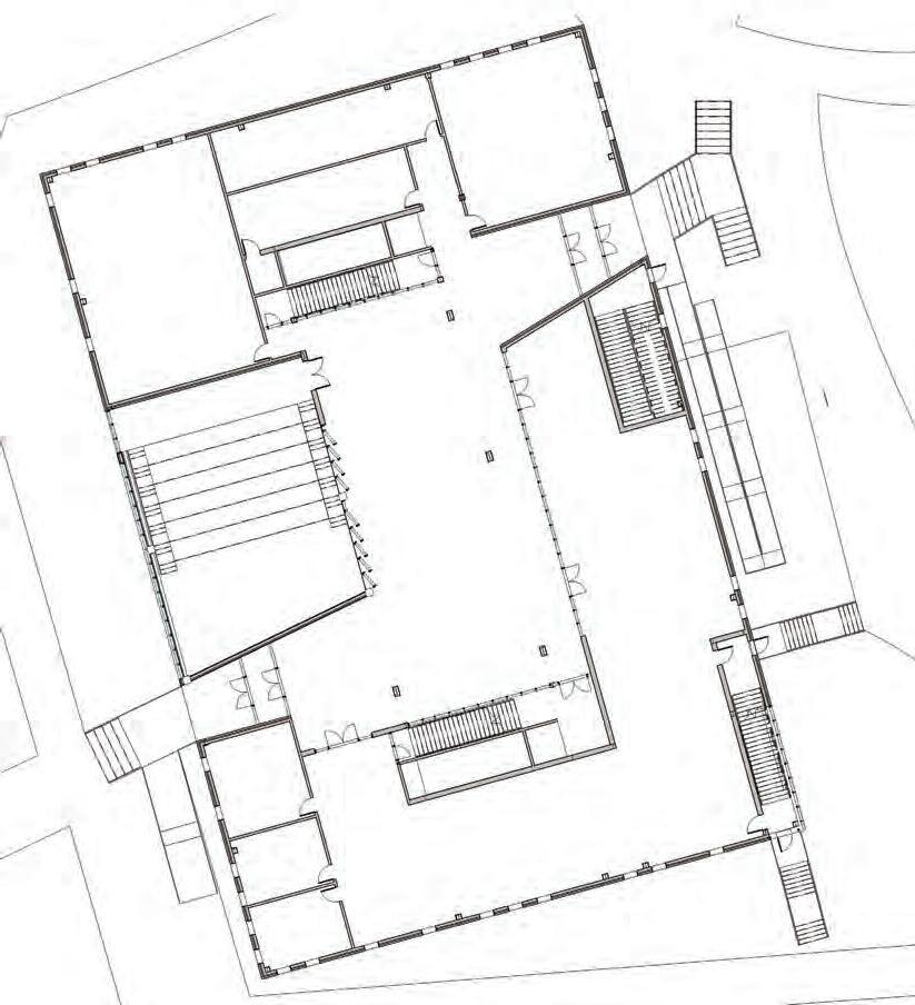


PROGRAM LAYOUT

SCALE: 1” = 20’-0”
SCALE: 1” = 20’-0”


SCALE: 3/32” = 1’-0”


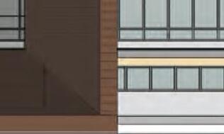
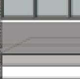


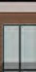


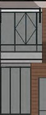

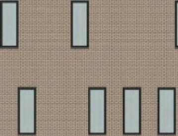

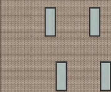
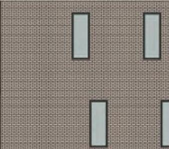


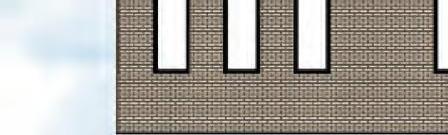


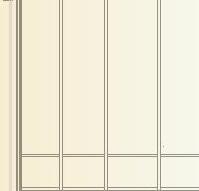
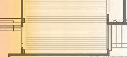
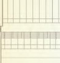
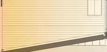
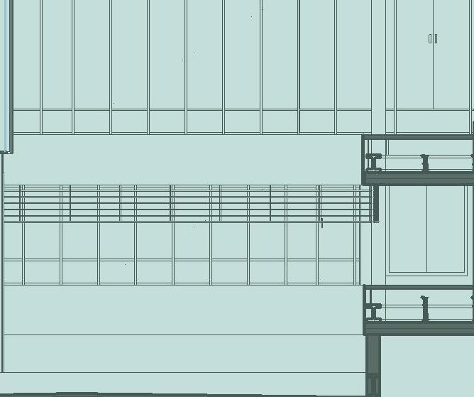
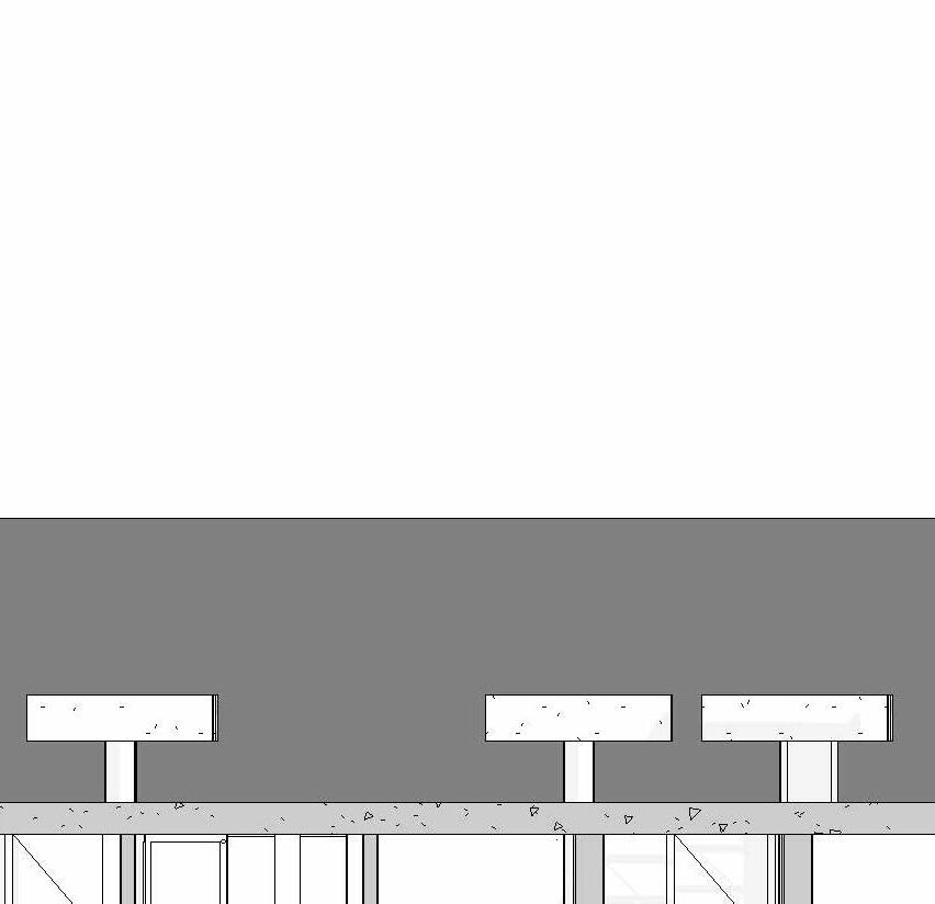
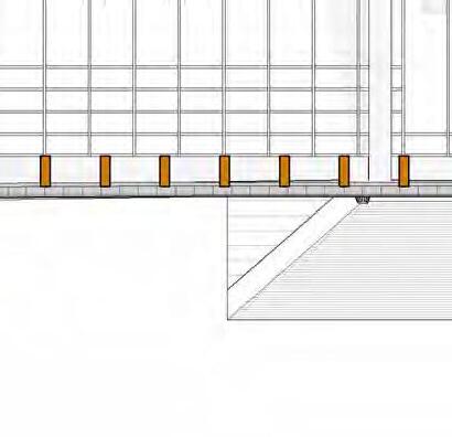
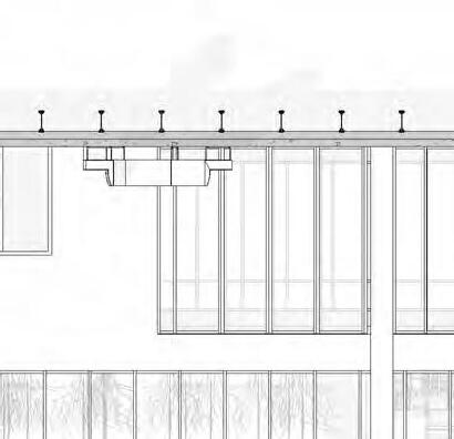
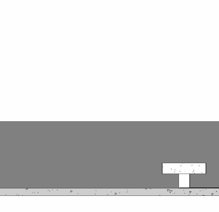
EAST ELEVATION


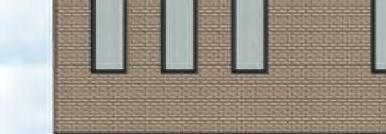
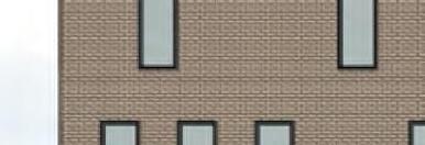
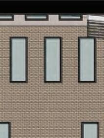
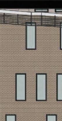


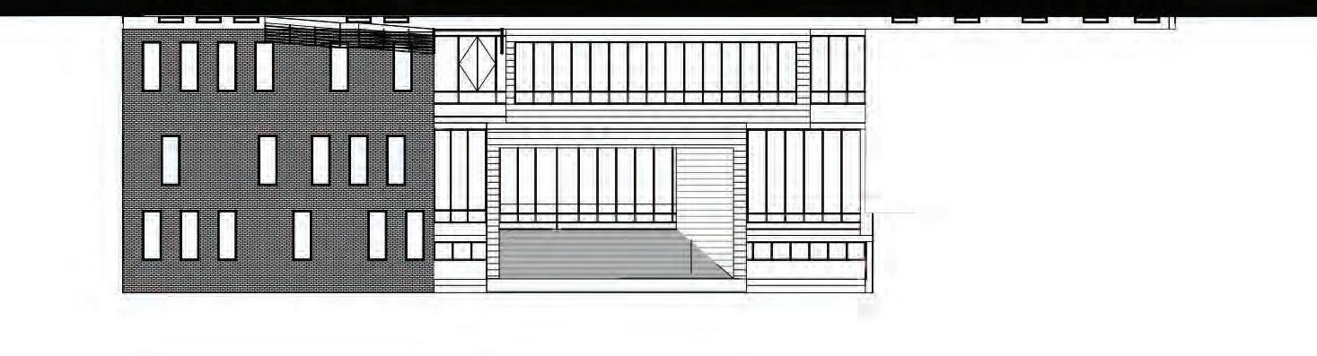
SCALE: 3/32” = 1’-0”


SOUTH ELEVATION
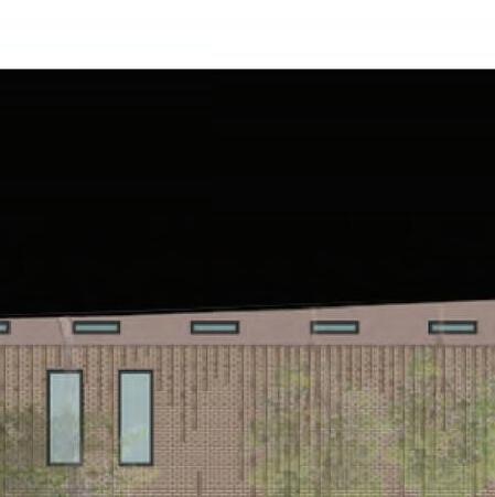
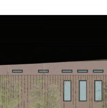
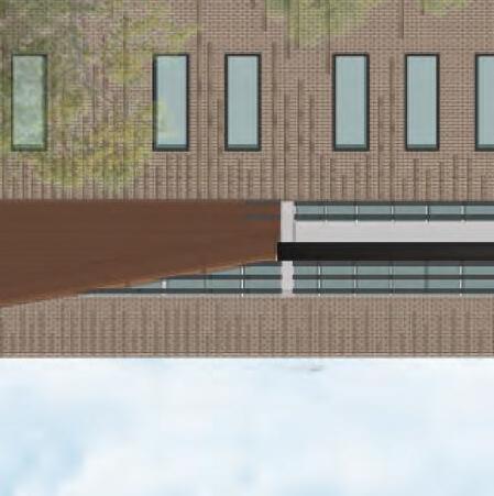
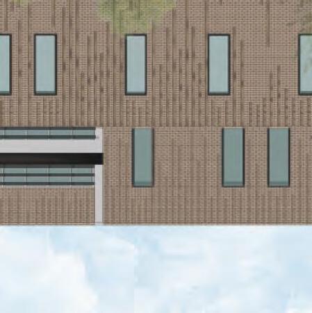
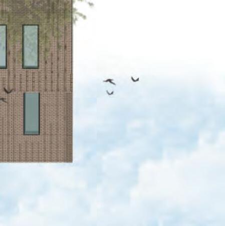
SCALE: 3/32” = 1’-0”


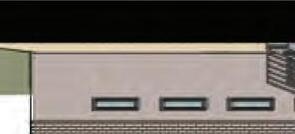


WEST ELEVATION

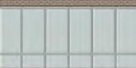

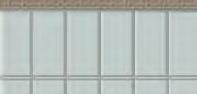


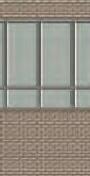
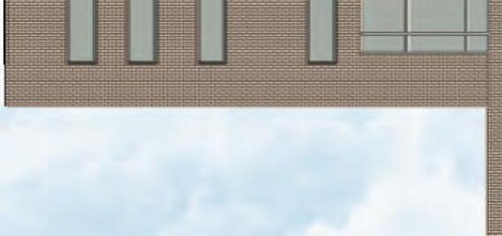
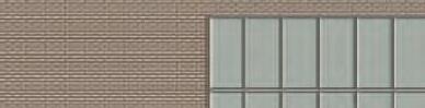
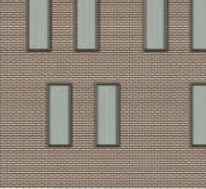
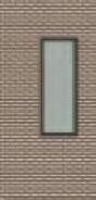
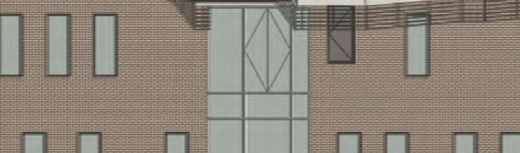
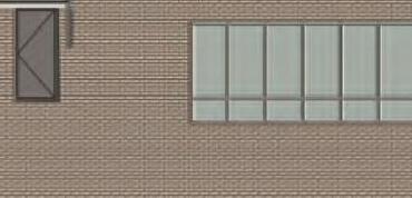
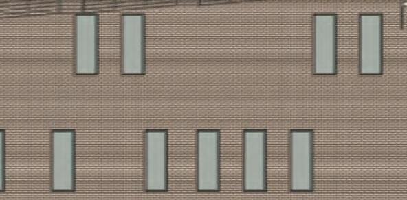


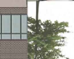

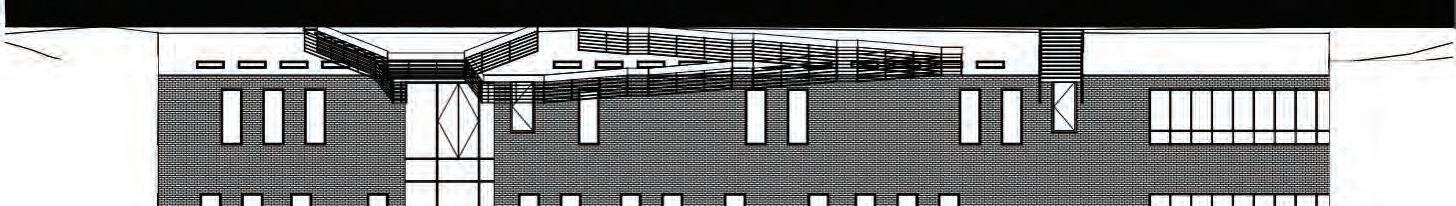
SCALE: 3/32” = 1’-0”


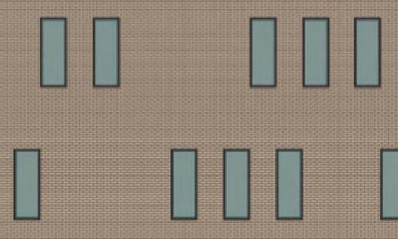


NORTH ELEVATION


SCALE: 3/32” = 1’-0”


SCALE: 1/32” = 1’-0”


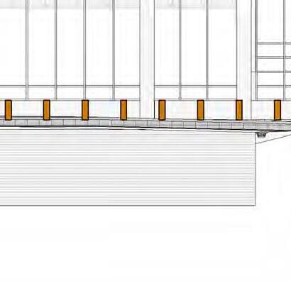
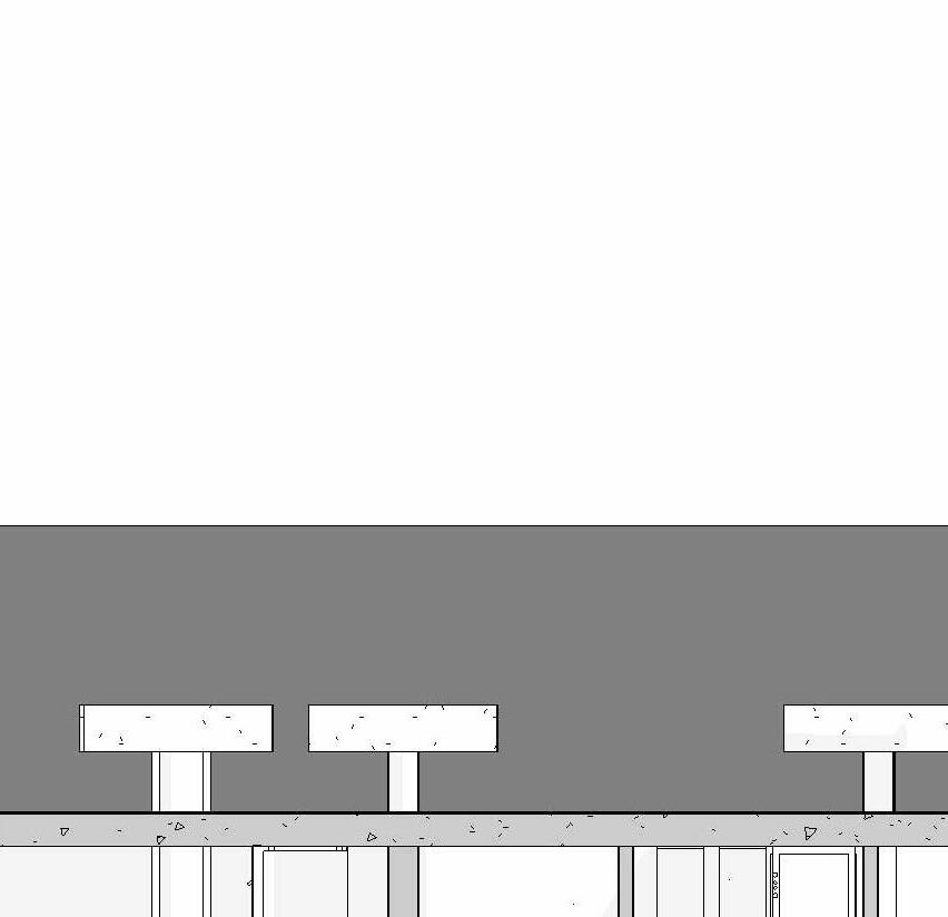
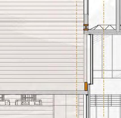
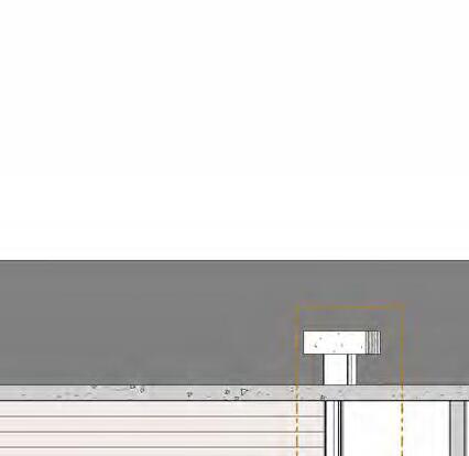
METAL FLASHING
SHEAR BOLTS
2X3 WOOD BLOCKING
WATER CONTROL MEMBRANCE
1/2" PLYWOOD SHEATHING
4" STANDARD BRICK
ADJUSTABLE BRICK WALL TIE
1" AIR SPACE
VAPOR BARRIER
2" RIGID INSULATION
6" STEEL STUD PLACED @ 24" O.C. WITH BATT INSULATION IN CAVITY
STEEL C - CHANNEL
5/8" GYPSUM WALL BOARD
DRIP EDGE
PARAPET ASSEMBLY
SCALE: 3/4”= 1’-0”
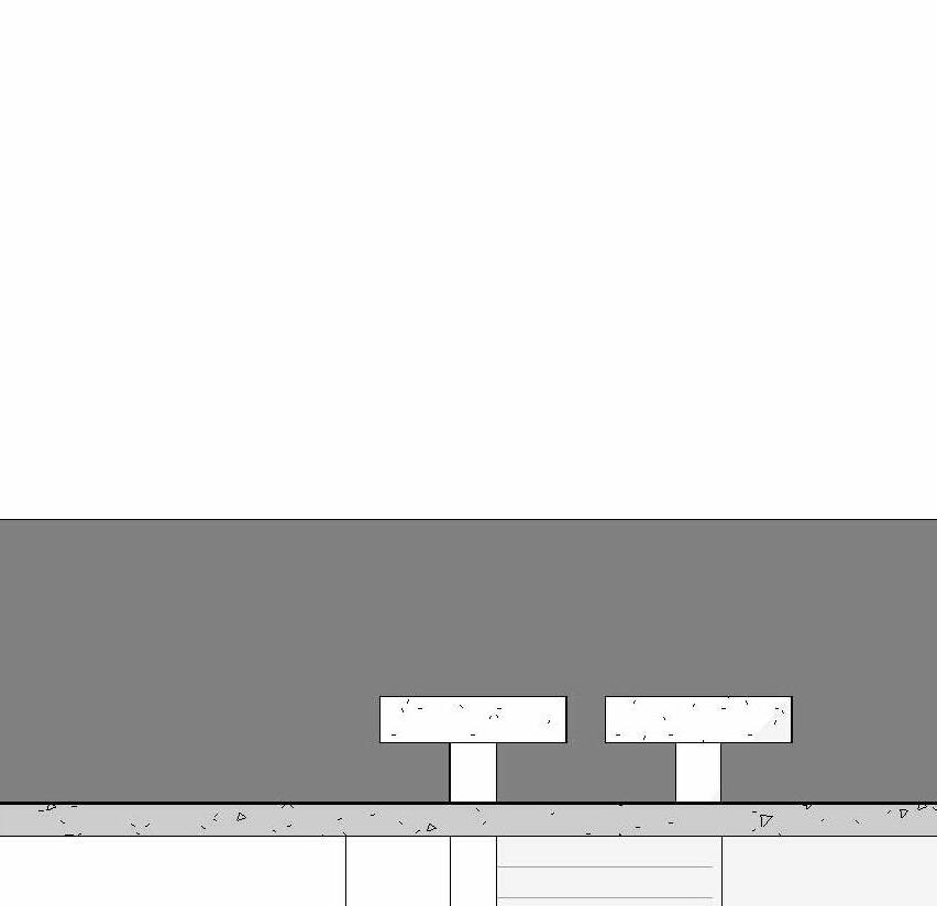
EDPM ROOF MEMBRANE
23/32" PLYWOOD SHEATHING
10" RIGID INSULATION SLOPED TOAWRDS ROOF DRAIN
METAL CHANNEL
STEEL BEAM CONNECTION PLATE
W12X336 WIDE FLANGE BEAM
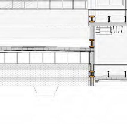
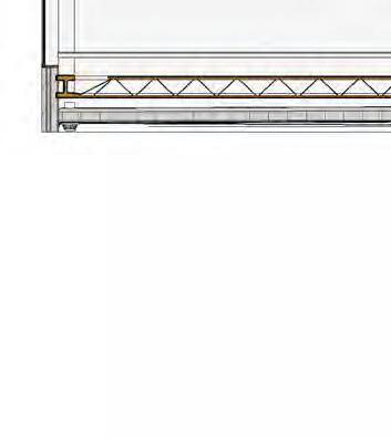
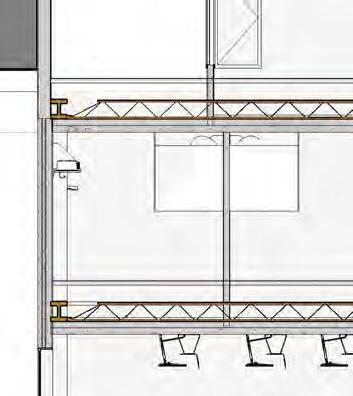
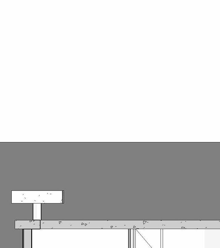
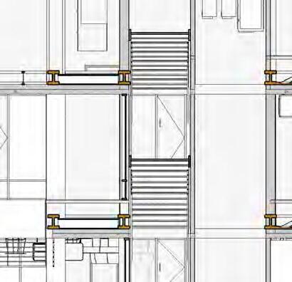
FLOOR ASSEMBLY
SCALE: 3/4”= 1’-0”
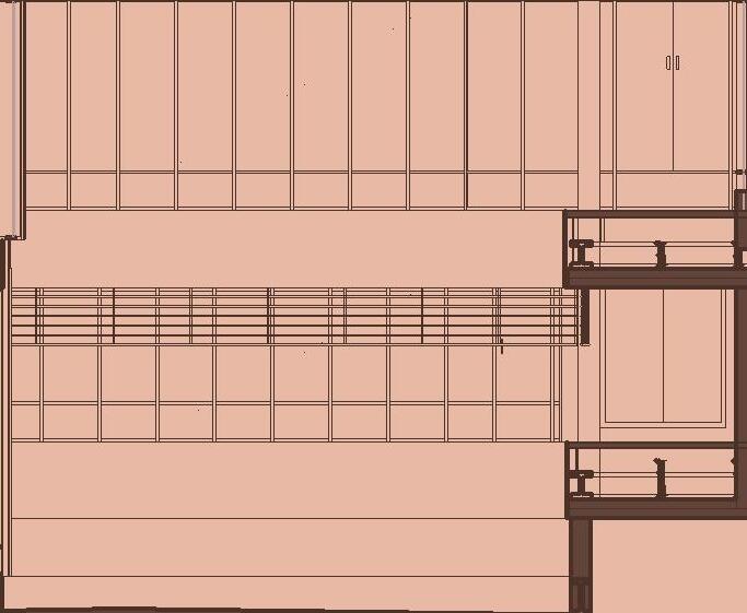
BRICK WALL SECTION
METAL SUSPENDED CEILING SUPPORT GRID
1/2" GYPSUM CEILING
WIDE FLANGE COLUMN WRAPPED IN GYPSUM
2 1/4" WOOD FLOOR FINISH
5/8" SUBFLOOR
6" CONCRETE FLOOR SLAB
3" METAL DECK
4" RIGID INSULATION
METAL CHANNEL
W12X336 WIDE FLANGE BEAM
STEEL BEAM CONNECTION PLATE
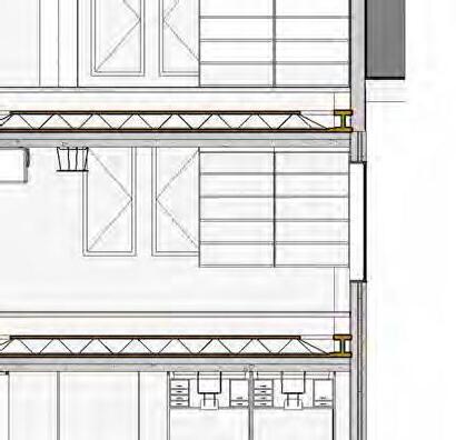
16K9 OPEN BAR JOIST
SUSPENDED CEILING ROD
METAL SUSPENDED CEILING SUPPORT GRID
1/2" GYPSUM CEILING
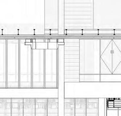
3'X8' FIXED WINDOW WITH ALUMINIUM FRAMING
3'X8' FIXED WINDOW WITH ALUMINIUM FRAMING
FLOOR ASSEMBLY DETAIL
3'X8' FIXED WINDOW WITH ALUMINIUM FRAMING
12" CONCRETE FOUNDATION WALL
6" METAL STUD @ 24" O.C. WITH BATT INSULATION IN CAVITY
5/8" GYPSUM WALL BOARD
2 1/4" WOOD FLOOR FINISH
5/8" PLYWOOD SUBFLOOR
6" CONCRETE FLOOR SLAB
VAPOR BARRIER
2" RIGID INSULATION
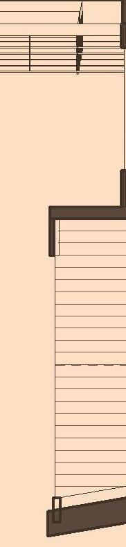
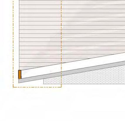
WALL SECTION
SCALE: 3/16”= 1’-0”
EDPM ROOF MEMBRANE
1" PROTECTION BOARD
8" RIGID INSULATION
2 1/4" WOOD DECK
6.75X24 GLUELAM BEAMWESTERN SPECIES
18X18 HEAVY TIMBER COLUMN
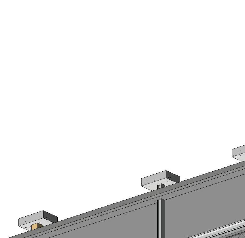
STEEL CONNECTION PLATE
8X26 GLUELAM BEAMWESTERN SPECIES
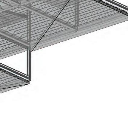
ROOF CONNECTION ASSEMBLY
SCALE: 3/4”= 1’-0”
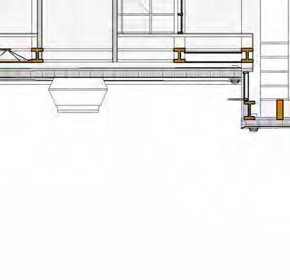
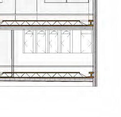
18X18 HEAVY TIMBER COLUMN
2 1/4" WOOD FLOOR FINISH
5/8" PLYWOOD SUBFLOOR
6" CONCRETE FLOOR SLAB
3" METAL DECK
4" RIGID INSULATION
16K9 OPEN BAR JOIST SUSPENDED CEILING ROD
METAL SUSPENDED CEILING SUPPORT GRID
1/2" GYPSUM CEILING
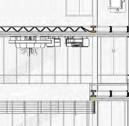
ATRIUM FLOOR ASSEMBLY
SCALE: 3/4”= 1’-0”
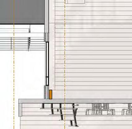
ATRIUM WALL SECTION
2 1/4" WOOD DECK
6X8 WOOD BLOCKING
8X32 GLUELAM BEAMWESTERN SPECIES
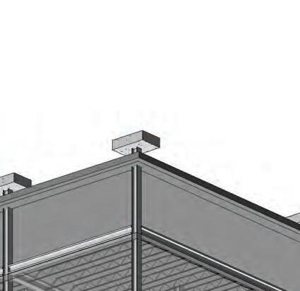
ROOF CONNECTION DETAIL
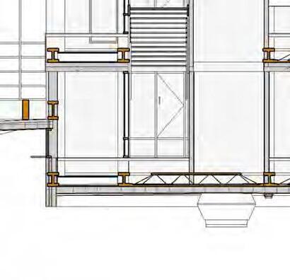
OPERABLE WINDOW FOR ATRIUM VENTILATION
REFER TO ROOF DECK DETAIL FOR ASSEMBLY
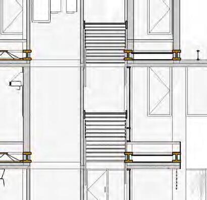
(2) 5/8" GYPSUM WALL BOARD SHEATHING
NRC ACOUSTIC PADDING
2" ACOUSTIC PANELS
METAL ZIP CLIPS RESILIENT CHANNEL
4'x10' CURTAIN WALL PANELS WITH ALUMINIUM FRAMING
W12X336 WIDE FLANGE BEAM
ATRIUM FLOOR ASSEMBLY DETAIL
6" METAL STUD @ 24" O.C WITH SOUND BATT INSULATION IN CAVITY
ACOUSTIC SYSTEM ASSEMBLY REFER TO ATRIUM FLOOR ASSEMBLY DETAIL
2 1/4" WOOD FLOOR FINISH
5/8" PLYWOOD SUBFLOOR
6" CONCRETE FLOOR SLAB VAPOR BARRIER
2" RIGID INSULATION
WALL SECTION
SCALE: 3/16”= 1’-0”
EPDM ROOF MEMBRANE
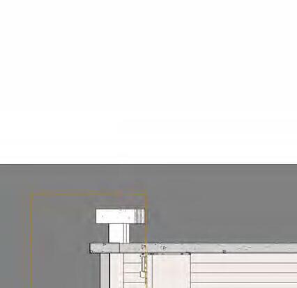
PERFORMANCE ROOF ASSEMBLY
SCALE: 3/4”= 1’-0”
2" WOOD DECK
2X4 ANGLED SLEEPER
EDPM ROOF MEMBRANE
VAPOR BARRIER
6" RIGID INSULATION
2 1/4" WOOD SUBSTRATE
2X10 WOOD BEAM SUPPORT TO CANTILEVER
6.75X24 GLUELEAM BEAM SPACED @ 4' WITH RIGID AND BATT INSULATION IN CAVITY
6.75X24 GLUELEAM BEAMWESTERN SPECIES
5/8" GYPSUM CEILING
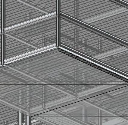
ROOF DECK ASSEMBLY
SCALE: 3/4”= 1’-0”
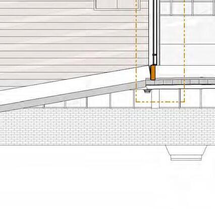
REHEARSAL WALL SECTION
VAPOR BARRIER
2 1/4" WOOD DECK
2X3 WOOD BLOCKING
EPDM ROOF MEMBRANE METAL FLASHING
STEEL BEAM CONNECTION PLATE
8X32 GLUELAM BEAMWESTERN SPECIES
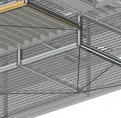
ROOF DECK DETAIL
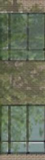
3'X2' GLASS CURTAIN WALL PANELS WITH ALUMINIUM FRAMING
3'X8' GLASS CURTAIN WALL PANELS WITH ALUMINIUM FRAMING
2" RIGID INSULATION
VAPOR BARRIER
RESILIENT CHANNEL
METAL Z CLIPS
1" X 4" STEEL EXTERIOR CLADDIND
6" METAL STUD SPACED @ 24" O.C. WITH BATT INSULATION IN CAVITY
ACOUSTIC SYSTEM ASSEMBLY REFER TO ATRIUM FLOOR ASSEMBLY DETAIL
12" CONCRETE FOUNDATION WALL
VAPOR BARRIER
2" RIGID INSULATION
WALL SECTION
SCALE: 3/16”= 1’-0”


 Roof drain, 15” strainer with 8” drain
SCALE: 1”= 20’-0”
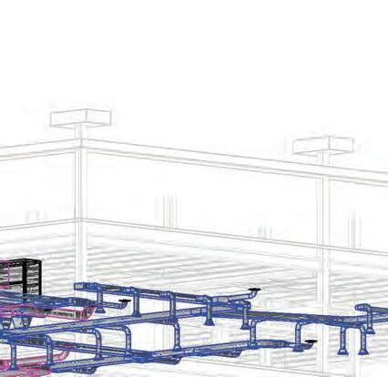
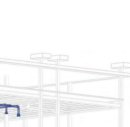
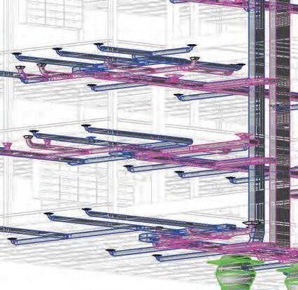
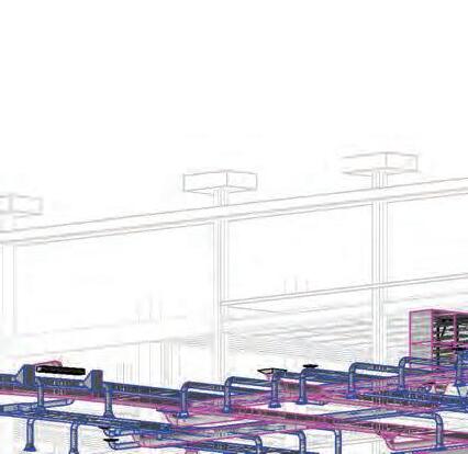
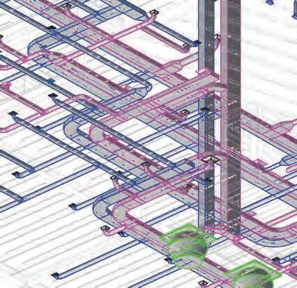
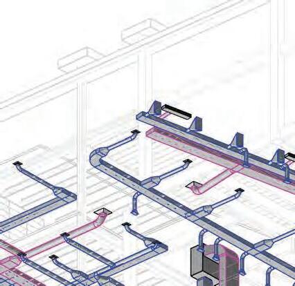
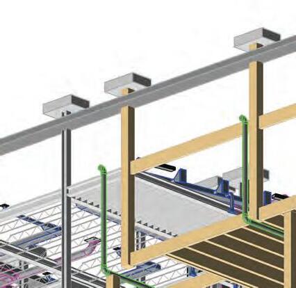
HVAC ZONE 1North section of building, 3 floors + basement
SUPPLIED BY: Vertical split system air handling unit, located in north vertical chase
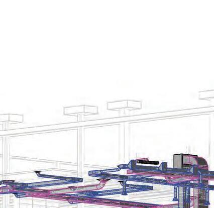
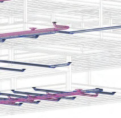
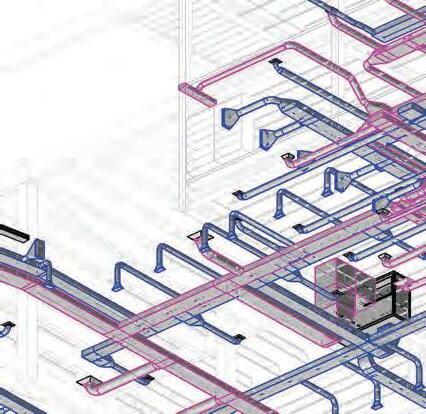
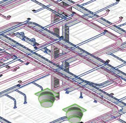
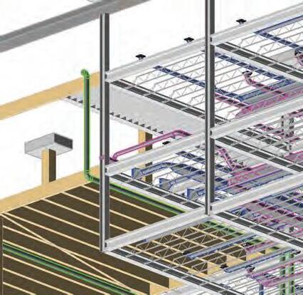
HVAC ZONE 2Atrium + Rehersal, first floor + basement
SUPPLIED BY: DX Vertical packaged air handling unit, located in building mechanical room
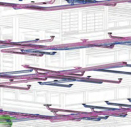
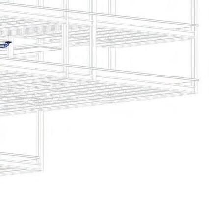
HVAC ZONE 3South section of building, 2 floors + basement
SUPPLIED BY: Vertical split system air handling unit, located in south vertical chase


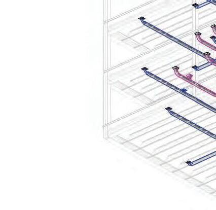
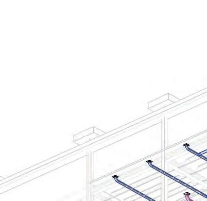
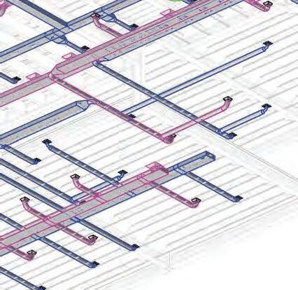
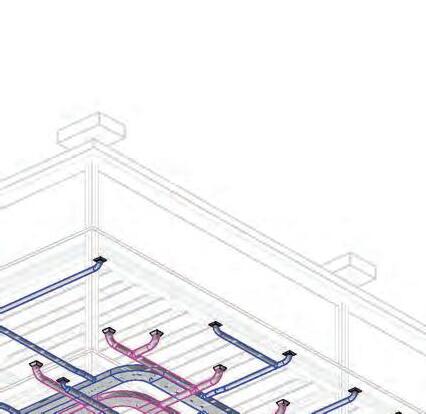
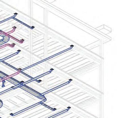
Supply air terminals: 12” x 12” diffuser with 8” diameter neck
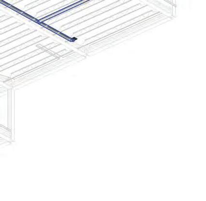
Supply branches: 18” x 8”
Return branches: 24” x 8”
Supply branches: 8” diameter
Return branches: 12” diameter
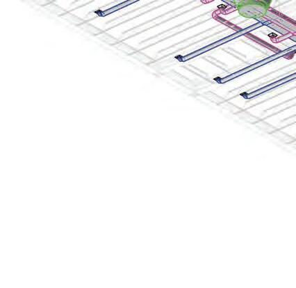
Supply air terminals: 12” x 6” perforated supply grille, supplying atrium above
Air Handling Unit: Vertical split
Return air diffusers: 24” x 24” diffuser with 12” diameter neck
Return air diffusers: 12” x 12” diffuser with 12” diameter connection
SCALE: 1”= 20’-0”
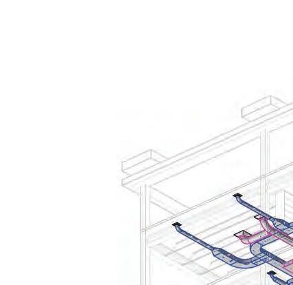
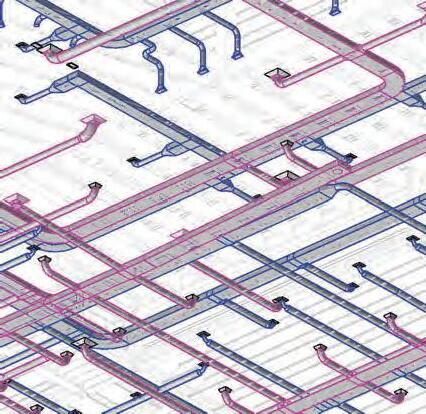
Supply trunk: 24” x 16”
Return trunk: 36” x 16”
Return air diffusers: 60” x 5 1/4” linear 3-slot hosted diffuser with plenum, returning rehersal space
Supply air terminals: 4’-0” x 6’-0” sidewall diffuser, supplying rehersal space
Air Handling Unit: DX Vertical packaged
Return trunk: 36” x 36”
Supply trunks: 24” x 24”
Return trunk: 36” x 16”
Supply trunk: 24” x 16”
Air Handling Unit: Vertical split system
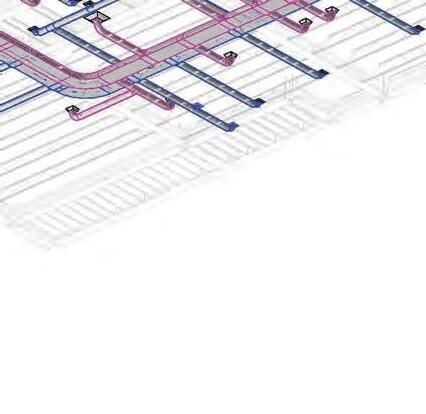
NOTE: All supply components used throughout buildinng are specified on “Basement Mechanical” sheet
NOTE: All return components used throughout building are specified on “Basement Mechanical” sheet
NOTE: All supply components used throughout building are specified on “Basement Mechanical” sheet
SCALE: 1”= 20’-0”
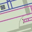
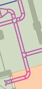
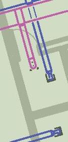
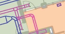
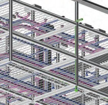
Supply
Return
NOTE: All return components used throughout building are specified on “Basement Mechanical” sheet HVAC
SCALE: 1”= 20’-0”
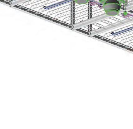
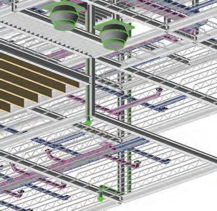
Rooftop centrifugal exhaust fan
Supply
Return
Rooftop centrifugal exhaust fan
NOTE: All supply components used throughout buildinng are specified on “Basement
Mechanical” sheet
NOTE: All return compoonents used throughout buildinng are specified on “Basement
Mechanical” sheet
NOTE: All supply components used throughout building are specified on “Basement


Mechanical” sheet
NOTE: All return components used throughout building are specified on “Basement
Mechanical” sheet
NOTE: All supply components used throughout building are specified on “Basement Mechanical” sheet
NOTE: All return components used throughout building are specified on “Basement Mechanical” sheet


Rooftop centrifugal exhaust fan
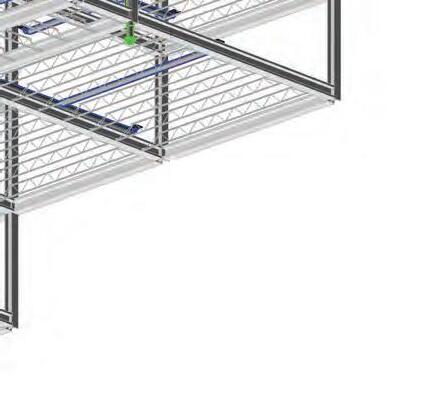
Supply
Return
Rooftop centrifugal exhaust fan
Return
Supply
NOTE: All supply components used throughout building are specified on “Basement

Mechanical” sheet
NOTE: All return components used throughout building are specified on “Basement
Mechanical” sheet
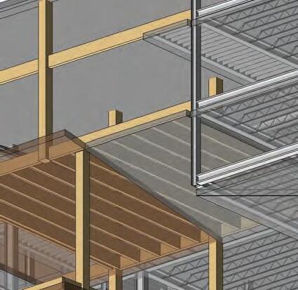
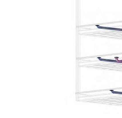
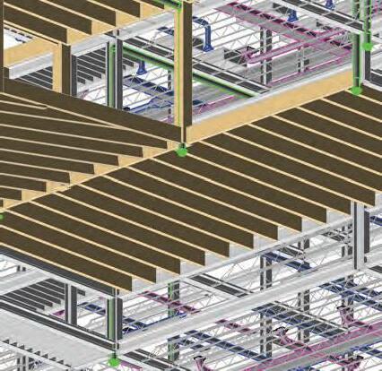
NOTE: All structural components used throughout building are specified on “Structural Axonometric” sheet

 Rooftop centrifugal exhaust fan
Roof drain, 15” strainer with 8” drain
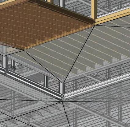
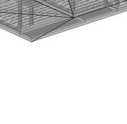
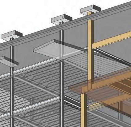
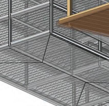
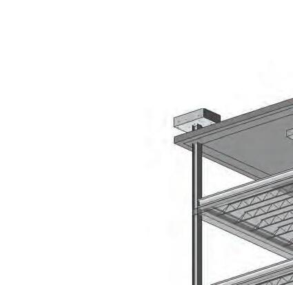
Steel structural system
Rooftop centrifugal exhaust fan
Rooftop centrifugal exhaust fan
Roof drain, 15” strainer with 8” drain
Steel structural system