Mechatronics Electronics in products and processes
D.A. Bradley
Department of Engineering University of Lancaster, UK
N.C. Burd
National Semiconductor GmbH Fürstenfeldbruck, Germany
D. Dawson
Engineering Department Lancaster University, UK
A.J. Loader
Digitron Redditch, UK
SPRTNGER-SCTENCE+BUSTNESS MEDIA, B.V.
Preface
1 What is mechatronics?
1.1 Mechatronics in manufacturing
1.2 Mechatronics in products
1.3 Mechatronics and engineering design
1.3.1 A modular approach to mechatronics and engineering design
1.4 The engineer and mechatronics
1. 5 Mechatronics and technology
Part One Sensors and Transducers
2 Measurement systems
2.1 Sensors, transducers and measurement
2.2 Classification
2.2.1 Classification by function
2.2.2 Classification by performance
2.2.3 Classification by output
2.3 Developments in transducer technology
2.3.1 Solid state transducers
2.3.2 Optical transducers
2.3.3 Piezoelectric transducers
2.3.4 Ultrasonic transducers
2.4 Signal processing and information management
2.5 The design of a measurement system
3 Resistive, capacitive, inductive and resonant transducers
3.1 Resistive transducers
3.1.1 Potentiometers
3.1.2 Strain gauges
3.1.3 Resistive temperature transducers
3.2 Capacitive transducers
7
7.1.3
7.2
7.2.1
7.2.2
7.2.3 Noise
7.2.4
8 Signal processing
8.1 Operational amplifiers
8.1.1 Integrator
8.1.2
8.1.3
8.1.4
8.1. 5
8.1. 6
8.3
8.1.8
8.3.3
8.4
12
19.2
Part Four Systems and Design
Part Five Case Studies
Preface
The need for an integrated approach to the design of complex engineering systems involving electronic engineering, mechanical engineering and computing has become increasingly apparent in recent years and has led to the growth of the concept of mechatronics. However, it is a concept which is as yet not particularly well defined; a broad range of interpretations has been placed upon it. The following definition has been adopted within the EEe:
Mechatronics is the synergetic combination of precision mechanical engineering, electronic co.ntrol and systems thinking in the design of products and processes.
From this definition it is clear that mechatronics is not itself a separate discipline within the overall spectrum of engineering but rather represents an integration across a number of different fields within engineering.
This text is therefore an attempt to set out the nature of mechatronics for a broad engineering audience. In order to achieve this objective the text aims to provide an indication of the range and scope of a mechatronic approach to the design of engineering systems and to identify the major areas of technology involved in such systems. It has its origins in the engineering degree course at Lancaster University and, specifically, in Professor Michael French's concept that engineering design should form a connecting theme throughout the whole of this course. As the course developed it became clear through links wth industry and through involvement in the Cambridge University based advanced course in design, manufacturing and management, for which Lancaster is the northern outpost, that there was an increasing need for engineering graduates who could function in an interdisciplinary environment. This led to the establishment in the late 1970s of a final year option course entitled 'the electromechanical interface' linking the two disciplines specifically in the area of drive technology. Then in 1985 an MEng course in mechatronics was established, the first such in the UK and from which the first graduates appeared in 1988.
The authors were all involved in the definition, setting up and teaching of the mechatronics MEng course and it was from this that the idea came about for
a book bringing together some of the concepts and material from the course. That the book has eventually seen the light of day owes much to a number of people. Michael French, the Professor of Engineering Design at Lancaster University, has already been mentioned and we owe much to his ideas on the nature of engineering design. Tony Dorey, the Professor of Electronic Engineering at Lancaster University, has also provided much advice and encouragement throughout this period, while other members of staff of the Engineering Department have advised and commented on items within the text. Away from Lancaster, many thanks must go to Sid Dunn for reading the manuscript and for his invaluable comments. At Chapman and Hall, Dominic Recaldin displayed admirable perseverance. Indeed, this was particularly notable in view of the problems created by the fact that although all the authors were members of the same department when the book was started, two later left to take up other appointments in Germany and the Midlands respectively. Thanks must also go to those companies who supplied information either for inclusion in the text or as background. It must, however, be emphasized that the opinions and conclusions are throughout the authors' own and do not represent those of the companies concerned.
Finally, thanks must go to the members of the authors' families for putting up with strange hours and bursts of work as deadlines approached and for the support they proVided throughout; this contribution was perhaps the most valuable of all.
D.A. Bradley
D. Dawson
N.C. Burd
A.J. Loader
Chapter 1
What is mechatronics?
The success of industries in manufacturing and selling goods in a world market increasingly depends upon an ability to integrate electronics and computing technologies into a wide range of primarily mechanical products and processes. The performance of many current products - cars. washing machines. robots or machine tools - and their manufacture depend on the capacity of industry to exploit developments in technology and to introduce them at the design stage into both products and manufacturing processes. The result is systems which are cheaper. simpler. more reliable and with a greater flexibility of operation than their predecessors. In this highly competitive situation. the old divisions between electronic and mechanical engineering are increasingly being replaced by the integrated and interdisciplinary approach to engineering design referred to as mechatronics.
In a highly competitive environment. only those new products and processes in which an effective combination of electronics and mechanical engineering has been achieved are likely to be successful. In general. the most likely cause of a failure to achieve this objective is an inhibition on the application of electronics. In most innovative products and processes the mechanical hardware is that which first seizes the imagination. but the best realization usually depends on a consideration of the necessary electronics. control engineering and computing from the earliest stages of the design process. The integration across traditional boundaries that this implies and requires lies at the heart of a mechatronic approach to engineering design and is the key to understanding the developments that are taking place.
Engineering design and product development are. as illustrated by Figs 1.1 and 1.2. complex processes involving an interaction between many skills and disciplines. Mechatronics is not a distinctly defined. and hence separate. engineering discipline but is an integrating theme within the design process. In achieving this integration it combines. as shown by Fig. 1.3. its core disciplineselectronic engineering. computing and mechanical engineering - with links into areas as diverse as manufacturing technology. management and working practices.
The foundations of a mechatronic approach to engineering design are
Identification of
Analysis
Propose and
evaluate solutions
Select
solution Prototype and test
Finalize design Manufacture
Costing
Figure 1.1 The engineering design process. Aesthetics
Materials
Manufacturing technology
considered to lie in information and control. Indeed. it may be objected in some quarters that mechatronics is 'only control engineering' in another guise. Such objections would. however, fail to recognize the direct impact on the approach to the design of a mechanical system of the introduction and incorporation of electronics and computing technologies. Indeed. a feature of a mechatronic approach to engineering design is that the resulting mechanical systems are often simpler. involving fewer components and moving parts than their wholly mechanical counterparts. This simplification is achieved by the transfer of
Production
Product development
IManufacturing technology
Electronic engineering
Figure 1.2 Product development.
I Financial I r Management control
Mechanical engineering
Computing
Education and training
Working practices I and Marketing industrial relations
Figure 1.3 The elements of mechatronics.
1
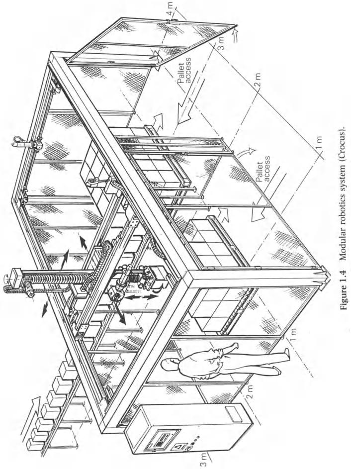
complex functions such as accurate positioning from the mechanical system to the electronics. An example of this is seen in the modular robotics system of Fig. 1.4. Here. encoders for position measurement together with electronic motor control have enabled the use of simple chain drives and induction motors instead of the expensive leadscrews and servomotors that would previously have been required. and which perhaps would have been too highly specified in terms of accuracy and resolution for the intended applications.
To be successful. a mechatronic approach needs to be established from the very earliest stages of the conceptual design process. where options can be kept open before the form of embodiment is determined. In this way the design engineer. and especially the mechanical design engineer. can avoid going too soon down familiar and perhaps less productive paths.
The first examples of mechatronic systems. albeit in a somewhat cumbersome and less capable and adaptable form. were to be found in the early computer numerically controlled (CNC) machine tools and in large scale automated processes such as chemical plant or rolling mills. However. in the majority of such systems the basic mechanical design was largely unaffected by the addition of electronically based control systems. Indeed. such control systems were regarded by many design engineers as a somewhat suspicious and mysterious bolt-on adjunct. Such inhibitions would now be a serious constraint on the ability of mechanical engineers in particular to exploit the opportunities made available through the incorporation of electronics.
1.1 Mechatronics in manufacturing
In the manufacturing industries there is a demand for production systems which are capable of responding rapidly to changing market conditions. accommodating a range of product types with short production runs involving relatively small numbers of items. Neither manual manufacturing processes nor mass production lines can meet these requirements. The former. though highly adaptable. suffer from low levels of productivity. The assembly and transfer lines associated with the latter lack flexibility. with changeovers involving significant time costs.
Within a wide range of manufacturing systems and processes. a mechatronic design approach has had as its primary benefit the ease with which the process can be reconfigured while. at the same time. offering enhanced product quality and consistency. The effect of a failure to adapt can be seen in the inability until quite recently of a range of UK capital equipment manufacturers. particularly of machine tools. injection moulding equipment. shoe making machinery. textile machinery and confectionery equipment. to supply systems of comparable performance to those of overseas competitors at a comparable price. Even where extensive government support was provided. a trend towards increasing import penetration was recorded.
A major reason for this failure can be identified in terms of the machine or system capability. UK produced equipment tended to be robust but lacking in the range of sensors and advanced state-of-the-art control systems offered by
their competitors. The resulting equipment was slower in operation. less adaptable to changes in product specification (with long set-up times) and. most importantly. less able to deliver a product of consistent quality.
Where full attention has been given to market trends. the adoption of an integrated mechatronic approach to design has led to a revival in areas such as high speed textile equipment. metrology and measurement systems. and special purpose equipment such as that required for the automatic in-wafer testing of integrated circuits. In most cases the revival or new growth is brought about by the enhancement of process capability achieved by the integration of electronics. often in the form of an embedded microprocessor. with the basic mechanical system.
This demand for increased flexibility in the manufacturing process has led to the development of the concept of flexible manufacturing systems (FMSs) in which a number of elements such as computer numerically controlled machine tools. robots and automatically guided vehicles (AGVs) are linked together for the manufacture of a group of products. Communication between the individual elements of the system is achieved by means oflocal area networks (LANs). Such interconnected systems operate in many implementations as a stand-alone grouping or island of automation within the production environment.
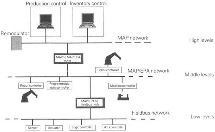
As levels of automation increase. so does the need for communications. This requirement has led to the introduction of the manufacturing automation protocol (MAP). the technical office protocol (TOP) and the open systems interconnection (OSI) standard to provide a communications structure for the passage of information throughout the whole of the manufacturing environment. as illustrated by Fig. 1.5. These concerns are also having a major effect
Figure 1.5 A hierarchical communications system for manufacturing control.
Production
Table 1.1 Comparison between a traditional and a mechatronic approach to process control and manufacturing
Traditional approach
Chemical process
Centralized computer control
All instruments, transducers wired back to central computer and control room
Sequence control predominates
Individual parts of the process relatively inflexible
Control systems involve the large scale use of electropneumatic interfaces because of hazard concern
'Hard' process, e.g. bottling plant
Sequence control predominates
Whole process controlled by relay logic
Highly inflexible as to product size and type; an 'army with spanners' needed to change conveyor guides etc.
Two-position air cylinders or simple electro pneumatics widely used, control by limit switches
Inspection/QA stages towards or at end of process
Manufacturing unit e.g. machine tool
Dedicated CNC controller, perhaps including automatic tool changes
Essentially stand-alone mode
Largely manual inspection and quality assurance procedures
Predominantly manua1-handling processes for loading and unloading
Plant maintenance on a breakdown or preventive basis
Mechatronic approach
Distributed processing power with localized decision making capacity
Reduced cable runs; machine cycles stored and executed via local control loops
More parts of process are capable of individual control
Optimization facilitated by stages and as a whole
Reduced size of components via VLSI results in lower power levels; may be intrinsically safe, therefore electronic controls become acceptable
Some proportional control where variable speed drives are used
Microprocessor based programmable logic controllers (PLCs) providing distributed control incorporating a degree of intelligence
Stepless actuators incorporating position feedback widely employed; process flexibility enhanced, downtime reduced
Robust electrical drives with variable speed and position feedback; proportional electropneumatics in limited applications
In-process automatic inspection
Networked CNC controllers with remote or central control of cycles
Linked flexible manufacturing system (FMS) with integrated parts handling and transfer, the latter based on the use of AGVs
In-process gauging, automated inspection, data collection and reporting
Use of general purpose robots for handling; automatic tool changing
Plant maintenance on a predictive basis, based on in-line diagnostics and condition monitoring
on the design integration of mobile systems such as vehicles. For example, where a vehicle has modular electronic controllers to handle the requirements of different systems such as a semi-active suspension and an anti-lock braking system, it is important that the modules should be able to interface to a common data bus. This is especially the case where the output of an individual sensor, say of wheel rotational speed, is used for different purposes. The more common use of such sophisticated techniques in vehicles has given impetus to the development of controlled area network (CAN) techniques - and a group of emerging standards to which all subsystem suppliers will be under pressure to conform if they are to remain competitive.
The process industries have seen the working together of mechanical, electrical and electronic engineering for many years, and the 'wet' process industry in particular has exhibited a significant degree of integration in its approach to system design, as exemplified by the high level of control engineering expertise to be found in companies such as ICI and Shell. Indeed, a chemical plant may be regarded as a mechatronic system in its own right, and in which the introduction of microprocessors and associated communications is having a significant impact through the opportunities offered for distributed control incorporating local decision making capacity. The introduction of decentralized systems has also brought about significant changes in procedures in areas of plant optimization, diagnostic based maintenance and data handling.
In both the manufacturing and process industries the development of low cost microprocessor based programmable controllers has enabled their introduction as the basic control element for many plants. In addition, there has been a progressive development in sensor technology, often employing very large scale integration (VLSI) technologies to provide 'smart' features such as self-calibration, monitoring and test.
Some indication of the nature of the changes in capability and emphasis that have occurred as a result of the adoption of a mechatronics approach is illustrated, albeit in a very limited way. in Table 1.1, which shows some of the features which distinguish the trend.
1.2 Mechatronics in products
Within products the diversity and opportunity offered by a mechatronic approach to engineering design is to date largely unrealized. End user products are substantial revenue earners and it is possible here to distinguish between existing products offering enhanced capabilities and completely new product areas which would not have existed without a mechatronic design approach having been adopted from the outset.
In the first category the following are illustrative from many examples: Automotive engines and transmissions Engine and driveline management
systems leading to reduced emissions. improved fuel economy. protection against driver misuse by. for example. prohibiting excessive fuel flow at low speeds. anti-lock braking systems and selectable gear characteristics.
Cameras Automatic adjustment of focus. aperture and shutter speed to suit the prevailing conditions. leading to a virtual elimination of technical skillsexcept those of picture composition!
Power tools Modern power tools such as drills offer a range of features including speed and torque control. reversing drives and controlled acceleration.
Examples in the second category include the following:
Modular robotics
Conventional industrial robots are often limited in their operation by their geometry. By providing a range of structural components and actuators together with a central controller a modular robotics system has been made available. allOWing users to assemble robot structures directly suited to their needs.
Autopilots for small boats These are able to accept an input from a windvane. fluxgate compass or radio beacon and drive a tiller or steering wheel.
Video and compact disc players Video and compact disc systems involve complex laser tracking systems to read the digitally encoded signal carried by the disc. This control is achieved by means of a microprocessor based system which also provides features such as multiple track selection. scanning and preview.
A common factor in consumer mechatronics as exemplified by the above is the continuous improvement in capability achieved against a constant or reducing real cost to the end user. The capability of a mechatronic system. based as it often is on inexpensive components or modules. also provides a means to execute bespoke solutions to special problems.
1.3 Mechatronics and engineering design
In engineering design. a mechatronics approach represents and requires the integration of a wide range of material and information aimed at providing systems which are more flexible and of higher performance than their predecessors. and which incorporate a wider range of features. Thus. for full benefit and effect. mechatronics must be a feature of both the conceptual and embodiment phases of the design process.
In manufacturing. users are demanding a much higher degree of control of both the overall process and its components. This requires a knowledge both of the capabilities of these components and of the means by which they are integrated within the complete system.
In products. the concern is primarily with the provision of enhanced performance and increased ease of use and the user is not generally concerned with
the means by which these objectives are achieved. This means that in most products the microcontroller responsible for the enhanced performance is transparent to the user, whose interface effectively allows the selection of an option from a range of predetermined programs.
At present, and though many organizations are involved in the development of products and systems which are inherently mechatronic in concept and realization, the responsibility for managing the technical integration is often left to a systems department. Such departments often have no responsibility for the design process; their role is simply to ensure that any changes made by one functional design team are passed on to other related groups, a largely clerical activity. In a true mechatronic design environment the coordinating role is central to the design process and would contain much of the fundamental design effort, in both the conceptual and embodiment phases. This fact is increasingly being recognized, particularly in Japan where many organizations have a mechatronics department whose role is central to the design and development of the company's product range.
It is therefore fundamental to a mechatronics approach to engineering design that the integration of the electronics and computing technologies with the mechanical system is considered throughout the design process. For an established product or process a mechatronic approach may well be used to provide an enhancement of performance for the same basic design. In such an application it is likely that this represents only one stage in an evolutionary process and that subsequent developments will take account of the inclusion of electronics within the basic system.
1.3.1 A modular approach to mechatronics and engineering design
A mechatronic approach to engineering design is concerned with the provision of a structure within which the integration of the various technologies can be established and evaluated. In order to achieve this objective, a top down and information based strategy is suggested in which the overall system is broken down into a series of blocks or modules as in Fig. 1.6. The role of each of these modules is then as follows:
Environment module The environment module is concerned with those external parameters such as temperature range and load factors which will influence the operation of the complete system. Within the overall design they constitute a series of parameter boundaries within which the system must exist and function. The environment modules must therefore encompass features such as standards and codes of practice.
Assembly module The assembly module represents the physical realization of the mechanical and structural elements of the system. It is primarily concerned with parameters such as the properties of materials, structural
World Interface module
Processor module
Communications module
Actuation module
Measurement module
Software module
Assembly module
Environment module
Figure 1.6 The building blocks of a mechatronic system.
behaviour, form and context. Inputs to the assembly module consist of the motions provided by the actuation modules together with the conditions defined by the environment module. Output from the assembly module is provided by the measurement module. As the assembly module is concerned with the appearance of the system it must also contain an aesthetic element. Measurement module This is concerned with the gathering of information about system status and behaviour. Input parameters are physical properties
of the assembly module while output parameters are concerned with the nature of the information to be transmitted.
Communications module This is concerned with the transmission of information between modules within the system. Input and output conditions relate to the nature of the information to be transmitted. the distance over which it is to be transmitted and the operating environment.
Processor module This is concerned with the processing of the information provided by the measurement and interface modules. Input parameters include measured parameters and demand settings together with system parameters such as speed of operation. The outputs from the processor modules determine the operation of the actuation modules and provide information to the interface modules.
Software module This contains the operating instructions and defining algorithms for the system and controls the operation of the processor module. The nature and form of the software module is linked to that of the associated processor module.
Actuation module This represents the 'muscle' required in the system to change system conditions. Input conditions are set by the output of the processor module and outputs are defined by the type of motion required. Interface module This is concerned with the transfer of information between levels within the system and. at the highest level. with providing the necessary man-machine interface for the transfer of user information. Inputs and outputs are concerned with the nature of the information transfer involved.
At each level in the design process the nature of the functions to be provided by an individual module can be established. and so can the nature but not necessarily the form of the informationn to be transferred. Modules defined at a higher level in the design process will themselves form a mechatronics system in their own right. in which case a further set of modules may be defined describing the next level down in the design.
As an example of this approach. consider a requirement for a mobile robot to be used in firefighting and rescue. Such a robot would be required to negotiate regions where debris was lying. to climb over such debris in order to deliver a hose to the seat of the fire. and to remove casualties from danger. The robot would also be required to communicate with and receive instructions from a control centre and to deploy a range of sensors and systems, many of which may not be capable of being specified at an early stage of the design process. In the first stage of the design process the modules are used to define. in conceptual terms. the functions of the robot and its constituent elements. At this level. a decision may be made that a legged robot is required to provide the obstacle crossing capability defined in the environment module. Thus. in the high level representation. an actuation element may be simply defined within the actuation module as leg. This actuation element may now be considered as a mechatronics system in its own right. giving rise to a second set of modules which describe the functioning of the leg in more detail. Information about the
operation of the leg, for example a movement instruction, is passed from the high level communications system to the leg via the lower level interface module. The actual functioning of the leg to meet the required demand is then determined by the leg's own processor module.
The design process will proceed in a similar manner through successive levels, defining further sets of modules at each stage and eventually providing detailed designs for the individual components making up the leg. The adoption of this type of approach means that the detail design of each component of the complete system can be undertaken in the knowledge of its relationship with all other components within the system. The problem of managing such a design process is a complex one and has not as yet been fully addressed.
1.4 The engineer and mechatronics
As has already been seen, within engineering design mechatronics is concerned with both the conceptual and embodiment phases of the design process. This requires that throughout the design process the individuals involved must have a sufficient knowledge of what is, or is not, available in a particular area of technology in order to assess any possible contribution to the final design and to maintain control of the project as it progresses. This latter aspect is of particular importance in respect of the inevitable changes and modifications to the initial concept and specifications that will occur as the design process proceeds to the final, detailed stages.
The skills and capabilities needed by an engineer to operate with confidence in a mechatronic environment can best be illustrated with reference to a specific system on a prototype product, namely an adaptive or smart suspension for a medium weight truck.
This suspension system is based upon air springs, one for each of the six wheels carried on three axles, with sensors to measure the current vertical position, velocity and acceleration of each wheel relative to the body of the vehicle. The data from the sensors is transmitted to the on-board microprocessor based controller at 20 ms intervals, where it is used as the input to control algorithms based on a mathematical model of the suspension system. Fast acting cross-flow valves, operating under the control of the on-board microprocessor, are then used to modulate the pressures of the individual air springs; electrically switched, dual rate dampers permit adjustment of the vehicle's ride behaviour. The resulting system is shown in Fig. 1.7.
Three modes of operation are possible:
Static Static levelling is provided to enable the vehicle to adjust to loading dock height and to ensure a horizontal platform for live pallets.
Quasi-static Manoeuvres such as cornering and lane changing impose a lateral acceleration which would normally cause the vehicle to roll. In the design adopted, the onset of roll is anticipated by a sensor on the steering wheel. The controller then uses this information in combination with the
Damper
Air spring
Steering angle
Road speed
Brake signal
Loading height request
Microprocessor based controller
Height sensor
Cross-flow valve
Exhaust
Reservoir
Valve block
Figure 1.7 Configuration of a smart semi-active suspension for a medium weight truck.
vehicle speed data to determine the operation of electropneumatic valves to transfer air to the outer air springs. simultaneously switching the dual rate dampers to the hard mode.
Dynamic The response of the vehicle suspension to short period events such as those caused by crossing rough ground is monitored at each wheel. The damper rates are than adjusted to give the desired ride quality.
The realization of the system from concept to hardware and software. primarily by a single individual. requires the exercise or development of competence in the following areas of skill and knowledge:
1. The mathematical modelling of mass. spring and damper systems with multiple degrees of freedom; system representation and programming using numerical integration techniques;
2. The selection and application of sensors;
3. Instrumentation generally. including the use of portable data collection and test equipment;
4. The design and application of electrohydraulic and electropneumatic control systems;
5. The use of microprocessor based development systems;
6. The establishing of control algorithms for system development;
7. The more general mechanical design of test equipment and pre-production items;
8. A general knowledge of analogue circuit design and electrical installations as appropriate to vehicles, sufficient to specify and in some cases construct signal conditioning and other circuits.
Taken altogether, this is a complex and challenging problem for an engineer!
1.5 Mechatronics and technology
Mechatronics is concerned with the bringing together and integration of certain key areas of technology, particularly: sensors and instrumentation systems embedded microprocessor systems drives and actuators engineering design.
In the case of sensors, instrumentation, drives and actuators the incorporation of local dedicated processing power within a device, enabling it to act independently of the main controller, provides increased system flexibility. Such smart sensors and intelligent actuators incorporating embedded microprocessors as part of a distributed system playa significant role in the design and development of a large scale mechatronic system.
The employment of a distributed system of embedded microprocessors means that communications and software engineering have important roles to play in any mechatronic design process. In the latter area, the adoption of a top down modular approach to the design of complex mechatronic systems means that techniques such as object oriented programming can readily be introduced for software development as the information transfer is defined by the module structure.
This text is therefore structured around a discussion of these four major elements in order to indicate the form and nature of the questions and problems involved in developing a mechatronic approach to the design process. The discussion is intended not to provide a detailed description of all the possible options that exist in an individual area, but rather to identify the technologies and their mode of deployment in relation to the functioning of a mechatronic system.
Part One
Sensors and Transducers
Chapter 2 Measurement systems
The role of measurement is to provide information on system status which, in a mechatronic system, is used to control the operation of the system. This function is performed by the measurement modules of Fig. 1.6, which incorporate the necessary sensors and transducers together with any local signal processing.
Following the production of the high level functional specification for an individual measurement module, the designer is faced with the problem of choosing the appropriate measurement technology from a wide and growing range of such technology. For this reason, in the discussion of sensors, transducers and measurement within mechatronics, the concern is with the identification of the range and scope of measurement technologies available, of the questions that must be asked and of the decisions that must made. A detailed consideration of the full range of measurement technologies is, however, outside the scope of this presentation.
Measurement technology is not a new science but can be traced back to origins in trade, where the need to quantify, on a basis which was both repeatable and representative, the nature of goods on offer led to the introduction of standards for measures such as volume and weight. With the growth in science and technology as exemplified by the Renaissance, more and specific measuring instruments evolved to support the growing interest in and investigation of the physical world.
With the advent of the industrial revolution, instrumentation and measurement science began to be applied to manufacturing. The early instruments were analogue in nature and provided information about the basic physical parameters concerned with the operation of the process. Feedback was achieved by the operator who read the instruments and then made the necessary adjustments to maintain the process within the required bounds.
The next step forward came with the introduction of the steam engine and automatic feedback control mechanisms such as the Watt governor for speed control. Following this lead, instrumentation gradually became more integrated with the process, providing feedback information to a controller which when regulated the system behaviour with a minimum of manual intervention.
By the late 1960s the advantages of discrete control had been recognized and production processes were often controlled by relay based systems. Such relay controllers, though complex in configuration and layout, were relatively unsophisticated and incapable of handling complex information. The performance requirements of their associated sensors and transducers was correspondingly restricted to the supply of simple data at a level capable of being utilized by the controllers.
These conditions were largely maintained with the introduction of computer monitored, as opposed to controlled, systems in which the computer was used primarily in a supervisory role as a central machine receiving information sequentially from a number of radially connected outstations. With the advent of minicomputers such as the DEC PDP series, computer controlled systems increased in both number and scope, though they were limited in application by both processing power and cost. More recently, sophisticated microprocessor based programmable logic controllers together with distributed and embedded microprocessor systems have resulted in the complex interconnected designs that are now found in both products and manufacturing processes.
The growth in microelectronics and computing technologies from the mid 1970s that made available low cost processing power has resulted in a parallel growth in the demand for information about system conditions. In many cases this increased demand could not be met by existing sensors and transducers and resulted in the development of a range of advanced sensors and transducers, often incorporating local processing power, either integral with the sensing element on the same silicon slice or in the form of a single chip microprocessor.
2.1 Sensors, transducers and measurement
In any measurement system, sensors and transducers are used to provide information about system conditions. Unfortunately, the usage of the terms 'sensor' and 'transducer' is complicated by the variety of different meanings adopted internationally, including in some instances an apparent interchangeability. For the purpose of this book the following definitions are adopted:
Sensor That part of the measurement system that responds to the particular physical parameter to be measured.
Transducer That component of the system that transfers information in the form of energy from one part of the system to another, including in some cases changing the form of energy containing the information.
In addition to a sensor/transducer, a measurement may include a pre-processing stage and a post-processing stage, as shown in Fig. 2.1. The pre-processing stage serves to characterize the information in the incoming signal before presentation to the sensing element. This then detects and responds to the physical stimulus at its input and provides the input to the transducer. The output signal from
Input Pre-processing Sensor/ Post- Output stage transducer processing st age
Figure 2.1 Pre- and post-processing of measurement data.
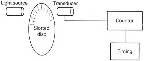
Figure 2.2 Speed measurement using a slotted disc with optical sensors and transducers. the transducer is then operated on by the post-processing stage to produce the final output. The relationship between these stages is illustrated by the optical encoder used for speed measurement shown in Fig. 2.2. Here, the light from the source is pre-processed by the slotted disc to produce a series of pulses. These light pulses are received by the transducer which converts the signal into a series of electrical pulses. The post-processing stage then counts the number of pulses occurring in a defined time interval to determine the speed of rotation of the shaft carrying the encoder.
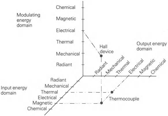
As has been stated, the physical basis for the transmission of information by a transducer is that of energy transfer. This concept has been developed by Middelhoek (see Bibliography) to identify six signal energy domains for the transfer of information. These domains are as follows:
Radiant This covers the full spectrum of electromagnetic radiation. Major parameters are frequency, phase, intensity and polarization.
Mechanical This covers parameters such as distance, velocity, size and force.
Thermal This covers temperature effects in materials, including parameters such as thermal capacity, latent heat and phase change properties.
Electrical This covers electrical parameters such as current, voltage, resistance and capacitance.
Magnetic This covers magnetic field parameters such as field strength and flux density.
Chemical This covers the internal structure and behaviour of matter and includes parameters such as concentrations of material. crystal structure and aggregation state.
Of these, the electrical output domain is the most significant in a mechatronics
(a)
Plug gauge (b) Plug gauge
Capacitive
Output sensor .f----.
Capacitive diaphragm pressure gauge Valve Air supply
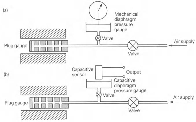
Figure 2.3 Pneumatic plug gauges with (a) direct dial readout (b) electrical output using a capacitive transducer.
context because of its information handling capability, and transducer outputs in other domains may well be further processed to transfer the information into the electrical domain. Figure 2.3 illustrates this condition in relation to a pneumatic plug gauge used for measuring the internal dimensions of a cylinder. In the original system of Fig. 2.3a, the back pressure developed is read by a diaphragm pressure gauge in which the displacement of the diaphragm operates a mechanical linkage to move the pointer on the dial. By replacing the mechanical linkage with a capacitive displacement transducer as in Fig. 2.3b, an electrical output signal is provided. which can then be transmitted onwards via a communications link.
In terms of their utilization of energy, transducers may be considered as direct or passive, requiring no energy source other than that provided by the input signal in order to function, and indirect or active, when an additional energy source must be provided. Examples of direct transducers are photoelectric devices and thermocouples, where the input energy is in each case directly converted to electrical energy. Indirect transducers include strain gauges and Hall effect devices, in which the incident energy is used to modulate an electrical signal. The additional. or modulating, energy input required by an indirect transducer must itself be derived from one of the six energy groups already referred to. This has resulted in the three-dimensional representation of Fig. 2.4, on which all transducers, whether direct or indirect, can be located by reference to their input energy domain, their output energy domain and any modulating energy source.
Figure 2.4 Three-dimensional representation of sensor and transducer operating energy domains.
2.2 Classification
It is possible to further classify transducers in a variety of ways. for example in terms of their performance. their function or their output signal. Each of these. and any other. classification can be used. as illustrated by Fig. 2.5, to identify transducers for a particular application.
Figure 2.5 Transducer selection chain.
2.2.1 CLASSIFICATION BY FUNCTION
In a mechatronic system the majority of measurements will be concerned with providing information about parameters in the mechanical domain. Typical measurands within this domain are as follows:
Force Absolute, relative, static, dynamic and differential pressures; torque; power; (stress).
Other Hardness; viscosity.
Similar functional tables can be drawn up for each of the other domains identified earlier.
2.2.2 CLASSIFICATION BY PERFORMANCE
Performance can be assessed in terms of parameters such as accuracy, repeatability, linearity, sensitivity and range. The selection of an appropriate device then requires that the available devices must be examined against each of the relevant performance parameters in terms ofthe application under consideration to produce a subset of suitable devices.
2.2.3 CLASSIFICATION BY OUTPUT
Output signals fall into one of a number of groupings as follows:
Analogue output Provides a continuous output signal, some property of which is directly related to the value of the measurand.
Digital output Generates a digital representation of the measurand in either serial or parallel form. Information may be produced either at regular time intervals or on demand.
Frequency output A signal is produced, the frequency of which is a function of the measurand. Output may be a continuous or a pulsed waveform which can be readily converted to a digital format by the use of counters and timers.
Coded output Various forms of coded signal can be produced including amplitude and frequency modulation, pulse width and pulse position modulation.
Provided overall performance parameters are met, the choice of transducer is not necessarily dependent upon the nature of its output, as the use of analogue to digital (A/D) and digital to analogue (D/ A) converters enables a signal in either the analogue or the digital domain to be used to generate an equivalent signal in the other domain.
Input Sensor/ Analogue Analogue Analogue AID transducer data signal data converter processing
f Control Control t Digital Digital data processing
D/A converter
Digital output Analo ue out ut g p
Figure 2.6 Simplifiyed schematic diagram of an integrated smart sensor.
2.3 Developments in transducer technology
Developments in transducer technology include the introduction of solid state silicon based transducers. optical systems incorporating fibre optics. piezoelectric devices and ultrasonic transducers. together with enhanced signal processing techniques. In particular. the introduction of local signal processing. often on the same chip as the sensor and transducer. has led to the development of the concept of the smart sensor. shown in schematic form in Fig. 2.6.
2.3.1 SOLID STATE TRANSDUCERS
The development of thin and thick film technologies has resulted in the production of a range of largely silicon based transducers for a wide selection of physical properties. In addition. micro-machining has enabled the creation of complex mechanical structures at the chip level. particularly the beams and diaphragms required for strain gauges. accelerometers and pressure gauges. However. even more complex structures such as gears. levers and motors have been shown to be capable of production on chip.
The continued development of solid state transducers based on silicon and other semiconductor materials is likely to have advantages in terms of reliability. signal conditioning. reduced signal-to-noise ratios and cost.
2.3.2 OPTICAL TRANSDUCERS
Fundamental to optical sensing technology are developments in lasers. photodetectors. fibre optics. optical materials and signal processing. the
combination of which has resulted in the provision of optical transducers for measurement applications ranging from distance to strain. In addition, developments in camera technology have led to the introduction of vision systems for measurement purposes.
2.3.3 PIEZOELECTRIC TRANSDUCERS
Piezoelectric devices have been used for many years as the basis for miniature accelerometers and ultrasonic ranging systems. The development of surface acoustic wave (SAW) technology has led to the introduction of transducers for applications such as gas detection and pressure sensing
2.3.4 ULTRASONIC TRANSDUCERS
Ultrasound is increasingly being used as a means of providing non-invasive measurement in environments ranging from process control to medical imaging. Such non-invasive measurements can:
1. Reduce the level of hazard when working with explosive, radioactive, poisonous, corrosive or flammable materials;
2. Avoid the contamination of materials such as drugs or foodstuffs;
3. Simplify maintenance procedures by enabling direct access to the sensors and transducers.
Measurements using ultrasound rely on the Doppler effect or the reflection, absorption or scattering of a pulse of ultrasound to generate the required information, often after significant signal processing.
2.4 Signal processing and information management
It is in the area of signal processing that computing technology has had the greatest impact upon the development of sensors and transducers. The availability of cheap local processing power has enabled compensation to be introduced for effects, such as a non-linear temperature coefficient, which would otherwise have rendered some technologies unusable, and has allowed for the conversion of the measured information into a form in which it can be transmitted over a communication link for further processing. Local processing power has also enabled the introduction of self-test and self-checking routines and the devolution of a decision making capability to the sensor/transducer.
At a higher level, the use of sophisticated data and signal processing techniques has enabled the development of the concepts of sensor fusion and data fusion in which information from a number of sources is combined to build up a picture of a complex system. Such an approach, when integrated with expert systems and artificial intelligence, offers increasing scope for development.
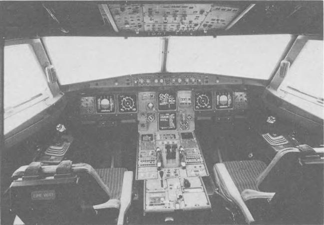
Information management and the presentation of data based on advanced signal and information processing techniques have an important role in the construction of a measurement system by ensuring that at any instant all necessary information is made available as required and that appropriate manmachine interfaces are available to present the data. An example of this is seen in the development of cockpit displays for civil and military aircraft, of which the A320 cockpit of Fig. 2.7 is an example. Here, the large number of individual gauges that were characteristic of cockpits have largely been replaced by visual display units on which the pilot receives the current flight and systems data. Should more detailed information be needed, either on demand or automatically in the case of a fault. these same displays are used for the presentation of the required data.
2.5 The design of a measurement system
Mechatronics implies an information based approach to engineering design, with measurement systems forming one element within the design concept. The primary function of the high level design process is therefore to establish the information required. Once this has been achieved, the design of the individual measurement modules can proceed to identify appropriate sensors, transducers and signal processing requirements to provide the required information. In this