Cooperative Systems Design Scenario based Design of Collaborative Systems 1st Edition by Carla Simone, Manuel Zacklad, Francoise Darses, Rose Dieng ISBN 1586034227 9781586034221
Embedded System Design Embedded Systems Foundations of Cyber Physical Systems and the Internet of Things 3rd Edition by Peter Marwedel ISBN 331956045X 9783319560458
ISBN 978-83-65596-31-4 ISBN 978-83-65596-32-1 (eBook)
The publication is available on license Creative Commons Recognition of authorshipNon-commercial use - Without dependent works 4.0 (CC BY-NC-ND 4.0) Full license content available on the site creativecommons.org/licenses/by-ncnd/4.0/legalcode.pl
The publication is available on the Internet on the site of the Printing House of Bialystok University of Technology
Technical editing, binding: Printing House of Bialystok University of Technology
Printing:
„UNI-DRUK” Wydawnictwo i Drukarnia Sp. J.
Edition: 43 copies
Printing House of Bialystok University of Technology ul. Wiejska 45C, 15-351 Białystok tel.: 85 746 91 37, fax: 85 746 90 12
MS – mechatronic system, MO – mechatronic object, MP – mechatronic process, CD – conceptual design, DD – detailed design, CS – conceptual studies, PC – personal computer, GO – geometric object, CAD – computer aided design, CAE – computer aided engineering, CIM – computer integrated manufacturing, KBE – knowledge based engineering, MDE – model-driven engineering, FBS – function-behavior-structure, FCBS – function-cell-behaviour-structure, FKC – functional knowledge cell, B-R – boundary representation, CSG – constructive solid geometry, ACS – automated computer system, HS – hierarchical system, DE – differential equations, CG – computational geometry, SRS – surgical robot system, TKA – total knee arthoplasty, MCM – manhole cutting machine, PCB – printed electronic circuit board, Coordination – systems design and control processes, Aed – formal analogous of two-level system with dynamic objects,
Sings and variables:
X – input,
Y – output,
S – system of level l,
S o – object of level l,
S – process of system S of level l,
S
– environment of system S ,
– structure of system S ,
0S – coordinator of system S ,
– aggregated dynamic presentation of system S ,
– reaction of system S ,
– function of states transition of system S , SL – numerical positional system,
– output function of coordinator (coordination strategy),
tt’ – time interval [t, t’],
– coordination signal and sub-systems connections, w – feedback signal.
PREFACE
This book presents the systemic model and coordination technology of hierarchical systems for conceptual design of mechatronic and other engineering objects. The conceptual model creation of the mechatronic system (MS) being designed is the actual task which is performed in the frames of automation and robotics, mechatronics, engineering design, computer integrated manufacturing (CIM), computer aided design (CAD) and other related subject fields. Conceptual model of the designed object is usually created before generating concrete mathematical models necessary for design tasks performing at the detailed design phase of the object life cycle [1].
Among the widespread models and methods which are usually used at the conceptual and detailed design phases are the following ones. Models of classical mathematics – discrete and continuous – successfully used to model the dynamics or structure of the object being designed, but do not solve the basic problem of design: do not link the structure of the object and its function. Models of artificial intelligence are most commonly used when describing the structure of the designed object and design knowledge representation Solving some specific design problems, these models remain one-level at its core and do not take into account the dynamics of the object being designed and therefore do not perform the general design task in one common theoretical basis. For the case of logical-dynamical systems, the dynamical elements of these systems are connected by logical systems in a higher-level structure, thus forming a higher-level system. Such systems are most useful in the design, but they take into account two levels of the designed objects only. Hybrid systems use the models of classic mathematics or artificial intelligence in that cases when they work most sufficiently, i.e. use the models of classic mathematics for description of systems dynamics or models of artificial intelligence for structure description of the object being designed. But it is impossible to represent both models of classic mathematics and artificial intelligence in the common formal basis. It complicates the performance of the general design tasks. Other methods and models are described in Chapter 1.
In the book presented, the conceptual formal model of mechatronic systems is created using construction and technology of hierarchical systems (HS) [2] with
their standard element aed by S.Novikava and K.Miatluk [3-8], dynamic systems by M. Mesarovic and Y.Takahara [9, 10], numeric positional systems and hierarchical geometry [7, 11, 52]. This conceptual model allows the connected formal descriptions of a mechatronic system structure, its aggregated dynamic representation as a unit in its environment, the system environment, its process and systemenvironment interactions; the system coordinator and its coordination, i.e. design and control, processes. Besides, the conceptual model takes into account the connected descriptions of mechatronic subsystems of different nature, i.e. mechanical, electronic, electromechanical, and computer. Availability of HS coordinator allows the realization of inter-level connections of mechatronic system being designed.
In this manuscript, the objects under consideration are designed and controlled mecharonic systems described in the theoretical basis of hierarchical systems (HS). The design and control process of mecharonic system is realized by HS coordinator. Mechatronic system (3.1) can be presented according to HS model in forms of mechatronic object (3.2) and process (3.3) being coordinated, i.e. designed and controlled (see Section 3.1). Therefore, mechatronic system (MS) in this book can be also called a mechatronic object (MO) or mechatronic process (MP) depending on the way of its consideration.
At the beginning, an overview of modern approaches and methods of conceptual design and engineering design methods are presented in this book in Introduction – Chapter 1. An overview of wide-spread geometric models which are used in CAD systems is given in Chapter 2. The formal basis of the conceptual model developed with the help of hierarchical systems, dynamic systems, and numeric positional systems is presented in Chapters 3. First, the standard block of hierarchical systems – aed (ancient Greek word) – a formal analogue of a two-level system [3,4] is described in Chapter 3. Formal modes of mechatronic object being designed, its environment and their processes are described using dynamic systems [9,10]. The main element – coordinator – which performs design and control tasks on its strata is formally presented using its canonic model. Metrical characteristics of hierarchical mechatronic systems including numeric positional system are given after that. Chapter 4 presents the description of the proposed design method and hierarchical geometric representations of mechatronic objects being designed. The exemplary tasks of the conceptual design of methatronic objects are presented in Chapters 5-9. Among the tasks there are biomechatronic surgical robot system (SRS) design, conceptual design of dinosaur Bioloid robot, human motion design, design and testing of electronic printed circuit boards (PCB), technological manhole cutting machine (MCM) design and control. Conclusive remarks are finally presented in the book.
1.INTRODUCTION – OVERVIEW OF DESIGN METHODS AND MODELS
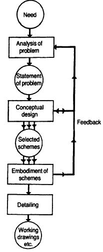
Conceptual model creation of an engineering, e.g. mechatronic system being designed is the actual task for automotive control, robotics and industrial production systems which usually operate with modern CAD/CIM systems [1, 12-15]. Nowadays, there are a lot of definitions of Conceptual Design (CD) and corresponding methods and models which are used at the conceptual design phase. The following definitions: “conceptual design or what some call ‘ideation’ defines the general description of the product” given by Paul Brown, “the early part of any design process, which can occur at any point in the product development cycle” given by Bob McNeel, and “conceptual design is about possibilities” given by Fielder Hiss are analyzed by Hudspeth [16]. Hudspeth considers conceptual design to be more about what a product might be or do, how it would meet the expectations of the manufacturer and the customer. M.J. French defines the conceptual design as the phase of the design process where the statement of the problem and generation of broad solution to it in the form of schemes is performed [17]. In any case before giving a definition to Conceptual Design and Conceptual Model of an engineering (e.g. mechatronic) object being designed it seems to be reasonable to define the place of Conceptual Design in general design process and object’s life cycle. To make such a definition, the general design scheme is presented by French [17] in the form of a block diagram given in Figure 1.1.
1.2. Mechatronic object life cycle [1]
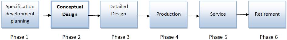
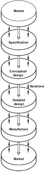
Here circles represent phases and rectangles represent work which is not completed. In this diagram things that are important but outside of the scope of the work, have been omitted by French. For examples, interactions with such activities as research and development, inputs of information, etc., were not under consideration. The ‘evaluation’ box was also omitted in the scheme because French believes it should be going on continuously in all the rectangles of the diagram [17]. According to Ullman [1], in the object life cycle (Fig. 1.2) the Conceptual Design phase is just before the phase of the Detailed Design (DD) where the object’s concrete mathematical model is created and numeric calculations are performed. Another similar scheme which contains both conceptual and detailed design phases in the total design core is presented by P. Childs in [13], see Figure 1.3.
Fig. 1.1. Block diagram of the design process [17]
Fig.
Fig. 1.3. The total design core [13]
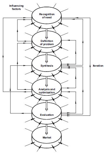
The main design tasks performed at both CD and DD phases (Fig. 1.3) are synthesis and analysis tasks. The places of these tasks in the general design process are presented by the scheme in Figure 1.4 given in [13]. Synthesis is defined by Childs as the process of combining the ideas developed into a form or concept, which offers a potential solution to the design requirement. Analysis task is recognized as involvement of the application of engineering science. In this case, subjects are explored extensively in traditional engineering courses, such as statics and dynamics, mechanics of materials, fluid flow and heat transfer. These engineering 'tools' and techniques are used in analysis tasks to examine the design to give quantitative information such as whether it is strong enough or will operate at an acceptable temperature [13]. Analysis and synthesis invariably go together.
In the frames of the conceptual design model presented in this book and described below in aed formal basis of HS (see Chapters 3-4), the synthesis and analysis tasks are also performed together and defined as coordinator tasks of creating (synthesis) and changing (after analysis) mechatronic system construction and technology by selecting units of lower levels and settling their interactions to make
the state and activity of the system on higher levels (environment) best coordinated with environmental aims.
1.4. Synthesis and analysis design steps in the general design process [13]
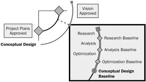
Another definition of the conceptual design process was given in the Overview section of the work titled “Analyzing Requirements and Defining Microsoft.net Solution Architectures” [18] where MSF (Microsoft Solutions Framework) process model was presented. It was pointed out here that the planning phase of the Model involves three design processes: conceptual, logical, and physical. The conceptual design starts during the envisioning phase of the MSF process model and continues throughout the planning phase. Because the MSF design process is evolutionary as well as iterative, conceptual design serves as the foundation for both logical and physical design. The following three steps of conceptual design and associated baselines are formulated. Conceptual design is an iterative process and the steps are repeated as required: 1) research, 2) analysis, 3) optimiza-
Fig.
tion. The optimization baseline leads to the baseline of the conceptual design. Correspondent Figure 1.5 illustrates these steps in the conceptual design.
During the research step of conceptual design, the team gathers more information to refine and validate data collected during the envisioning phase. Typically, the information gathered during the envisioning phase is high level and lacking in detail. During the first step of the conceptual design, the design team needs to collect detailed information. For example, the team first identifies questions raised by the first iteration of information gathering; the team then continues to clarify the tasks, business processes, and workflow. As greater detail is discovered, the results are incorporated in the use cases and draft requirements.
US Department of Transportation [19] formulated that conceptual studies (CS) are typically initiated as needed to support the design planning and programming process. CS phase identifies, defines and considers sufficient courses of action (i.e., engineering concepts) to address the design needs and deficiencies initially identified during the planning process. This phase advances a project proposed in the program to a point where it is sufficiently described, defined and scoped to enable the preliminary design and technical engineering activities to begin. The CS and preliminary design phases are performed in conjunction and concurrently with the environmental process which evaluates environmental impacts of the engineering proposals resulting from the conceptual studies and preliminary design phases. Environmental systems and processes are also taken into account in knowledge based engineering (KBE) approach proposed by Pokojski and Szustakiewicz in [20]. The main structures for extended KBE application are design process and design models. The models contain specific aspects such as product structure as a whole and its fragments, engineering calculations and analysis with ability of integration with external systems, design requirements and decision making processes. This object-oriented approach makes it possible to speed up the
Fig. 1.5. Steps in conceptual design [18]
process of generating the source code of design models from the extended KBE application. KBE approach is also used in [132] to support multidisciplinary design optimization. Another approach where the decision support tools in the domain of conceptual design are sufficiently developed is model-driven engineering (MDE) described in [21]. Here, a prototype software is presented that allows the user to specify functional requirements for the designed buildings, and hierarchical graphs and graph grammars serve as knowledge representation tool.
In systematic respect, designing is defined in [22] as the optimization of given objectives within partly conflicting constraints. Requirements can be changed with time, so that a particular solutions can be optimized for a particular circumstances set. In organizational respect, design is recognized as a part of the product life cycle. This cycle is trigged by a market need or a new idea. Life cycle starts with product planning and ends with recycling or environmentally safe disposal. The activity on engineering design is placed at the center of two interacting technical and cultural streams (Fig. 1.6) in [22].
From the point of view of Hierarchical Systems (HS) method proposed in this manuscript, both streams belong to the general process of level increasing of the object being designed in its life cycle. This process and the life cycle for the case of Tractor and Automobile Industry (TAI) were described in [23, 24] and are presented in Fig. 1.7 below.
Fig. 1.6. The central activity of engineering design [22]
Fig. 1.7. Main phases (1-5) of product life cycle and their places in State levels space [24]
Figure 1.7 presents the main phases of product life cycle for the case of articles of Tractor and Automobile Industry (TAI) and their places in State levels. States levels are (Nat) natural (physical, chemical, biological), (Demog) demographical (social), (En) engineering, (Kn) knowledge and the level of the State power (St.Power). The phases of TAI product life cycle are: (1) manufacturing of articles and equipment for TAI; (2) transport networks, the delivering of raw materials, details, equipment; (3) trade; (4) field of activity and technical service of TAI articles; (5) design of new things (innovations) in TAI, financial and juridical service, scientific maintenance. The place of the conceptual design phase where HS design technology and correspondent conceptual model (presented and described below in this book) are implemented is in the fifth block – design of new things, financial and juridical service, scientific maintenance – of the scheme (Fig. 1.7).
The connection of the Life Cycle phases (Fig. 1.7) as well as State levels –natural, demographic, engineering, knowledge, State power – is realized by aed technology of hierarchical system partially described by Aλ scheme given in [8]. The scheme connects elements of symbol construction of hierarchical system presented in Aλ form of aed and reflects both the design mechanism and the law of object’s level increasing in its life cycle.
To represent concept design knowledge, the technology of functional modelling was researched and applied by Bryant et al. [25]. Gero and Kannengiesser [26] presented an function–behavior–structure (FBS) ontology representation process for concept design in different domains, and emphasized the reasoning mechanism with the FBS ontology for knowledge representation. Borgo et al. [27] suggested an ontological characterization of artefact behavior and function to capture the informal meanings of these concepts in the engineering practice and to characterize them as part of a foundational ontology. As for
a mechatronic design process, Yan and Zante stated that "mechatronic system design is normally considered to be a sequential process in which a design solution to a given design problem is generated, explored and evaluated following a series of prescribed steps" [28]. A mechatronic approach towards designing inspection robots using rapid prototyping and real-time simulation is also described by Giergiel et al. in [29].
The design methods based on the abstract modelling of PALMERA and the DMC model, Design Flow for Reconfigurable Architectures (INDRA) has been developed to guide the designer through different implementation steps to create a concrete dynamic reconfigurable system architecture. These design methods and the design flow are described in [133, 134].
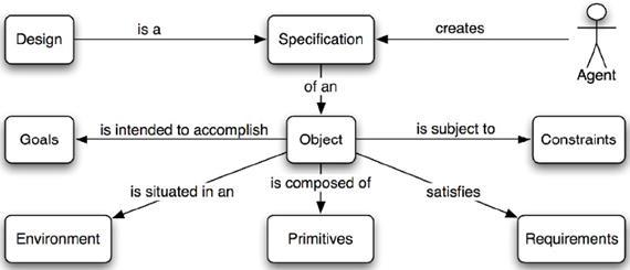
A formal definition of the concept design and a conceptual model linking concepts related to design projects are presented by Ralph P. and Wand Y. [30]. Their definition of design incorporates seven elements: agent, object, environment, goals, primitives, requirements and constraints. The design project conceptual model is based here on the view that projects are temporal trajectories of work systems that include human agents who work to design systems for stakeholders, and use resources and tools to accomplish this task. Ralph and Wand demonstrate how these two conceptualizations can be useful by showing that 1) the definition of design can be used to classify design knowledge, and 2) the conceptual model can be used to classify design approaches. The analysis performed by Ralph and Wand [30] led to defining the design as follows in Fig. 1.8.
Here the conceptual model of Design presented as a noun in Fig. 1.8 is recognized as a specification of an object, manifested by an agent, intended to accomplish goals in a particular environment using a set of primitive components, satisfying a set of requirements, subject to constraints. The Design recognized as a verb is presented to create a design in an environment where the designer operates.
Fig. 1.8. Conceptual model of Design as a noun [30]
Both noun and verb design definitions correspond to the object and its process respectively as the elements of aed model of HS conceptual design method suggested in this book, see aed scheme in Fig. 3.1, Chapter 3.
A systematic approach for the competency-oriented development of learning factories integrating the conceptual design levels ‘learning factory’, ‘teaching module’ and ‘learning situation’ is given by Tisch et al. in [129]. The presented approach enables “an effective competency development in learning factories by addressing problems of intuitively designed learning systems. As a result learning factories, teaching modules and single teaching–learning situations meeting industries’ requirements can be realized with less effort and an increased success in applied competencies in real situations”. A systematic analysis of mechatronic objects is also presented by Gawrysiak in [104].
The function–cell–behaviour–structure (FCBS) model for better comprehending representation and reuse of design knowledge in conceptual design was presented by Gu et al. [31]. Hierarchical two-layer concept is given here, i.e. two knowledge representing layers – the principle layer and the physical layer – are presented in the FCBS model. The principle layer is utilized here to represent the principle knowledge. Case modelling is employed in the physical layer to integrate the structural information and behavioural performances of the existing devices, which applies the design principles represented by the functional knowledge cells (FKCs).
FCBS model presented by Gu et al [31] and a formal definition of the concept design and a conceptual model given by Ralph P. and Wand Y. [30] are close to Hierarchical Systems design technology which is described below in this book and was chosen in this work as the formal basis of the conceptual model creation.
In the presented book the Conceptual Design (CD) is recognized as a process of creation of a systemic model of the object being designed on the early phase of its life cycle. To define the conceptual model of a mechatronic system in systemic bases it is necessary to describe: mechatronic system structure; its dynamic representation as a unit in its environment; the system environment, its process and system-environment interactions; the system coordinator and its coordination (design&control) processes; processes executed by mechatronic subsystems and a general process. Besides, the conceptual model should take into account the connected descriptions of mechatronic subsystems of different nature, i.e. mechanical, electromechanical, electronic and computer.
Furthermore, conceptual model of the mechatronic system being designed and its coordination (deisgn&control) technology should meet the requirements of the general design system which must allow performing the design – synthesis and analysis – and control tasks under condition of any information uncertainty, i.e. (1) to create and change mechatronic system construction and technology by selecting units of lower levels and settling their interactions to make the state and activity of
the system in higher levels (environment) best coordinated with environmental aims (selection stratum); (2) to change the ways (strategies) of the design task performing when the designed unit is multiplied and the knowledge uncertainty is removed (learning stratum); (3) to change the above mentioned strata when new knowledge is created (self-organization stratum).
The coordination technology must also cohere with traditional forms of information representation in mechatronics, i.e. numerical and geometrical systems. The theoretical basis of the design process in agreement with these requirements must be a hierarchical construction connecting any level unit with its lower and higher levels.
The above mentioned methods used in the conceptual design and well as models of mathematics based on set theory and methods of artificial intelligence do not meet the above formulated requirement. They do not allow the description of mechatronic subsystems with their specific characteristic features in common formal basis. At the same time they do not describe the mechanism of interlevel dynamics of the mechatronic object (MO) being designed since the set theory describes one-level world outlook only.
To solve the problem, the symbol construction and coordination technology of Hierarchical Systems (HSs) [2-8] was chosen in the work as the formal basis of the conceptual model creation. HS formal model was constructed with the help of aed (Fig. 3.1) – formal analogue of two-level system [3-8], and general dynamic systems by Mesarovic and Takahara [9,10], numeric positional system codes, geometry and cybernetics methods [32]
Among the first attempts of HS technology and aed model application in design are the results presented in [3-4, 33]. The current version of the conceptual model and design technology of mechatronic objects based on the Hierarchical Systems approach is partially described in [49] and presented below in this book.
2. GEOMETRIC MODELS IN DESIGN SYSTEMS
Geometric models of modern CAD systems which are used for solving the problems of mechatronics, robotics and automation are overviewed and analyzed in this Chapter. The overview covers recent decades, when almost all theoretical geometric models were realized in design systems and some new ideas were formulated. The main attention is paid to the models implemented in the systems which have their commercial realization.
There are two main classes of geometric representations in computer aided design (CAD) systems and other automated systems – Boundary Representation, B-R [34] and Constructive Solid Geometry, CSG [35].
An object being constructed is presented by expressions of CSG type in the form of a group of connected elementary objects (primitives) – cylinders, prisms, spheres, cones etc. The connection can be formally described by algebraic sum, i.e. some objects take part in this group with negative signs. CSG expression is graphically presented as a tree, whose root is the whole object. The object unites the details at each level, where the terminal tops (leaves) are primitives (Fig. 2.1).
Objects in B-R are represented by the set of parts of surfaces (sides) and the connections between the sides bytheir boundaries (edges) may be indicated (Fig. 2.1).
It is easy to see that B-R in this case contains the set of boundary elements of primitives which are used for uniting in CSG representation. At the same time, B-R contains only such boundary elements which are connected with the environment directly, and are not connected with each other in the whole object construction. Therefore, after defining each primitive in CSG model by its boundary representation and erasing common parts of their boundaries we obtain B-R of the whole object. It means that there is a simple transition from CSG to B-R but the reverse process is not so simple.
Primitives and more complex objects can be presented in algebraic form, which include patent, parametric [36], polynomial representations [37] and different types of splines [37, 38], and also in the form of sequences of Euler operators [39]. Geometric representation and parametric model of the object were proposed in the mid 80s of the 20th century. For geometric representation [40] the set of notions is introduced: {surface, point, vectors, scalars} .
Each of the notions can have a set of meanings in accordance with Table 2.1. It is easy to see that the meaning of variable “surface” in Table 2.1 plays the role of key and to each meaning of key there corresponds a strictly defined set of other variables in the same line in the table.
3D object
Constructive Solid Geometry expression
Boundary Representation
Fig. 2.1. Known basic geometric representations of object in CAD [140]
Table 2.1. Multitude of geometric characteristics meanings
Surfaces Points
Plane
Any point on the plane
Vectors Scalars
Unitary normal No
Sphere Center No
Rectilinear cycle cylinder
Any point on the axis
Rectilinear cycle cone Top
Unitary vector parallel to axis
Unitary vector parallel to axis
Radius
Radius, length of axis
Top angle, radius
There is a certain mutual concordance between the representation of primitive in the space of geometric characteristics and its algebraic definition in form:
Ax2 +By2 +Cz2 +Dxy+Eyz+Fxz+Gx+Hy+Jy+K=0, (2.1)
where: x, y, z are coordinates in 3-dimension Euclidean space. That means that there are algorithms for transformation of geometric representation to algebraic one and vice versa. Calculations presented in [40] show that geometric representations require the minimal computer memory in comparison with other forms of representation. Besides, it is well connected with the natural language, convenient for enquiring about searching for elements of the object and forming directives for its change. It is sometimes useful to calculate some metrical characteristics, such as volumes and squares of surfaces using geometric representation directly. But it is necessary to convert the geometric representation to other forms to calculate physical characteristics, to form graphic images and to determine the technological process.
Objects and their primitives can be presented by the sequences of Euler operators [39]. Therefore, objects are described by the sequence of constructing operators and inverse sets of destructing operators of geometric objects of a higher (in the case of destruction – lower) dimension. For instance, if we have an image of polyhedron we can erase one of its apexes (vertex) and save this operation on computer. After that we can erase another top which is located on the same edge. These two operations correspond to the operation of the edge erasing. The sequence of operations of erasing of all edges which form one polyhedron side corresponds to the operation of removal of the whole side and finally, the erasing of all the sides destroys the object.
The repetition of the chain of all the operations in the inverse sequence when destructing operations are changed by constructing ones allows the object to be rebuilt. Such direct and inverse chains are called Euler operators. Their name arose from Euler’s formula:
where: v – number of apexes, e – number of edges, f – number of sides.
Euler’s formula allows correctness of the object construction to be controlled. General formula which corresponds to the object of any connectivity is presented in the form of the expression:
e+f=2(s–h)+r, (2.3)
where: s – general number of untied components, h – number of through holes in object, r – general number of cavities in sides.
For the formation of graphic images Euler operators are one of the best expressions. At the same time their most effective application to computer raster terminal units is achieved by the hybrid connection of Euler operators with Octrees [41]. Such trees finally include the white and black leaves only (i.e. empty and filled elements of the object corresponding to cube primitives) but initially and in the middle state they have the grey leaves as well. Grey leaf corresponds to the case when one primitive simultaneously contains empty and filled areas. It is decomposed according to the general rule for each level till only black and white leaves remain.
Octrees is the most acceptable geometric model for raster graphics. The transition from Euler operators to Octrees is one of the way of transition from vector (which is most useful for the output of boundary expressions) to raster representation [42]. It is necessary to convert Euler operators to other forms in order to calculate functional characteristics of objects and to define technological processes.
The algebraic representations of geometric objects are well investigated [40, 43].
They are not practically used in requests to search the objects and are hard for their formation with participation of the user. There are some possibilities of connection of created in this way primitives in CAD systems with CSG representation. But connection algorithms of objects of various forms are very complex and require a lot of computer memory and time for calculation.
At the same time such representations are suitable for computer graphics tasks (in vector forms), for generation of some programs for automated production and are the most effective for calculation of many functional characteristics in many tasks of engineering analysis.
The most convenient way of forming an algebraic expression is the case when one of the input units of a computer is scanning a physically realized (or simply graphically written) object. In this case the unit forms a range of observations during a definite period of time which is changed later by corresponding mathematical definitions. It allows the information to be compressed and the initial range of observations to be restored when necessary.
Rational parametrical B-spline [38, 44, 45] gives the general form of any object’s surface representation in homogeneous, i.e. descriptive, coordinates.
The spline is obtained from common parametric B-spline in the following way. C(t) is polynomial B-spline curve in 3D Euclidian space, i.e.
where: Pi – 3-dimention control points, t – parameter, such as a t b & a, b are fixed and 0 a b; B(t) – polynomial of variable t of k order (power k-1). Bi,n(t) –basic functions defined by node vector
The representation of C(t) in homogeneous (descriptive) space with fourth coordinate hi has the following form:
where h i P is a control point in 4D space.
The corresponding spline representation for surface is defined by the expression:
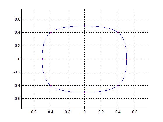
This approach allows good representation of both the objects which are usually described by manifest definition (cycles, cones, primitive cubes) and the objects which are defined with the help of the parametrical polynomial forms (sculptural surfaces) [45]. The exemplary 2D path generated based on p(x, y) points using Spline interpolation algorithm is presented in Fig. 2.2. Spline interpolation is used in this case to create the 3 degree polynomials for the set of measurement points of the cutting path. Technological process of the pipe cutting along the predefined path is realized by robot cutter or CNC machine in production environment [46].
First, 1D spline for x and y point is created independently. Then the 2D path is generated as the composition of 1D x and 1D y splines. The set of measurement points in this case is as follows: 00,40,500,40,50,40 x= and
0,50,400,40,50,400,5 y= , see Fig. 2.2.
The manifest functionsrequire more elementaryactions and lesscomputer memory for representation of primitive surfaces and lines. But the use of one general expression improves the characteristics of the system in general and allows the memory volumes for programs location to be reduced, the speed of operations to be increased and the dialogue with the engineer to be unified. At the same time the expenses of system development, exploitation and the amount of documentation are reduced.
Vertex list Edge list
V1(0, 0, 0)
V2(1, 0, 0)
V3(0, 1, 0)
V4(0, 0, 1)
e1[V1, V2]
e2[V2, V3]
e3[V3, V1]
e4[V2, V4]
e5[V4, V3]
e6[V1, V4]
2.3. Tetrahedron – an example of a wire-frame model
Fig. 2.2. 2D path generated based on p(x, y) points using Spline interpolation algorithm
Fig.
For the case of wireframe modeling [46], the model consists entirely of points, lines, arcs and circles, conics, and curves. In 3D wireframe model, an object is not recorded as a solid. Instead the vertices that define the boundary of the object, or the intersections of the edges of the object boundary are recorded as a collection of points and their connectivity (Fig. 2.3).
Wireframe models are most economical in term of time and memory requirements, easy to construct, used to model solid object and often used for previewing objects in an interactive scenario. At the same time the models have the following disadvantages. They do not allow for use of photo realistic rendering tools, have no ability to determine computationally information on mass properties (e.g. volume, mass, moment, etc.) and line of intersect between two faces of intersecting models and do not guarantee that the model definition is correct, complete or manufacturable.
To expand the potential possibilities of traditional boundary representation, the connections of dimensions (length, squares, volumes, angles) are added to algebraic expression in the process of forming the representation. It permits the process of parametric construction with the use of geometry of variations to be realized.
Parametric model, or which is often used for the representation of objects in data bases of design systems, is defined by set {T, D, O, V, R, C}, where: T – set of topologies, D – set of possible dimensions, O – set of operations, V – set of variables, R – set of relations between V and T/O/D, C – set of restrictions of the meanings of variables.
Any class of objects PS can be presented in these terms in the following form:
S ={
d, o, v, r, c}, (2.8) tiT, diD, oi
It is possible to create B-R defining T and D only. To create CSG it is necessary to define O
Therefore, parametric model of the object contains not only traditional representations (B-R in its most developed form based on geometry of variations) but also the relations between different forms of representations. Declarative definition of all the elements of set {T, D, O, V, R, C} ensure flexibility of the system, possibility of its adaptation to different classes of objects and optimization of system parameters in its functioning process (for instance, finding more effective operations, defining new relations, etc.).
Having many characteristic features of systems of artificial intelligence, parametric model has a drawback – its relatively weak formalization. Six elements presented above are not strictly defined. That makes the creation of such models very complicated for the user. In other words, sets of possible meanings (states) of objects T, D, O, V, R, C are not defined. Possible connections of these states, i.e.
states of the whole system, and transition operations from one possible state to another are not defined either.
A more theoretically grounded from the point of view of realization simplicity is the approach (independent from technical realisation) of graphical standard development proposed by CGS Associates [47].
This approach is based on the application of mathematical means of formal system theory and algebra for the development of data bases. GSC Associates has adapted its technology in its commercial software products. Some of these products are Computer Graphics Metafile (CGM) generator used by Apple, and CGM interpreter used by Microsoft, Apple and Symantec [47].
Geometrical objects are considered in [47] as formal systems which have their inputs, outputs, states and actions of state transitions. A set of the actions also contains the ways of obtaining information about the object’s state (states recognition).
Definite data structure of a data base corresponds to the formal system – abstract data type, which can be adapted to any concrete state (any data of this type) and the set of state transition functions, i.e. operations which do not take the elements out the frames of the abstract type being considered. For instance, the structure of group of integer numbers is defined on computer by a cell organised for representation of integer number as a positional number with a definite base and actions of adding and subtraction.
The cell can be in any of its states (can contain one of integer numbers presented in the computer numeric format). Each of the mentioned operations with the present number and some other number which goes to the cell input are performed with the help of sequence of elementary operations (with bits) and forms the output which is also an integer number, i.e. has the same abstract type.
Division operation does not belong to the group of integer numbers because it can take the elements out of the frames of this abstract type (it is necessary to have one additional cell for the division remainder). The fields of real and complex numbers, logical data are also realized in computers in the form of abstract data types.
With respect to geometric expressions, this approach means the representation of a geometric object in the form of abstract data type with a set of operations of states transition which do not take the elements out of the frames of this abstract type. For instance, the data structure “segment” can be defined by a set of axioms, limits and by the operations of motion on a straight line, rotation and change of length. The operation of arbitrary uniting of two segments is not included in the data structure “segment” because it can take elements out of the frames of this abstract type. For instance, it is possible to obtain the broken line or “+”-like object as a result of uniting two segments, i.e. lines.
Data structure of “segment” also contains the operations with it. The description of several connected data structures for vector computer graphics with similar organization is presented in [47].
In this case the analogy of parametric model set T, D, O, V, R, C is a set of notions of formal system theory which corresponds to the language of abstract data types. That means that the notions and their relations from this set are not only strictly defined and easy for programming but are realized in many cases as hardware.
So, concluding the overview of traditional ways of geometric information representations, it can be pointed out that the possibility of formal system theory and abstract data types application for the construction of expressions of geometric objects (models) opens new perspectives in CIM systems including robotics and CAD.
Both the CSG and B-R have their own advantages and drawbacks. So, the CSG models are simply constructed with the participation of a user. CSG model also requires less computer memory, is better adapted for definition of technological processes (for inst. assembling type) and for imitation of movements of object’s details.
On the other hand, B-R models can actually be built without human participation, allow the sculptural surfaces to be constructed, allow variations methods to be used, and are better adapted for calculation of technological processes of continuous deformation and for aerodynamic and hydrodynamic calculations.
The connection of these two approaches is possible, but sub-process of geometric constructions creating and changing for CSG differs in marked degree from this sub-process for B-R.
In the existing CAD-systems these are principally different design technologies. Integration of these approaches in one system can be possible in the case of existence of the general formal language which can contain both representations and transition operations from one to another. It looks like the hierarchical and general systems theory can give an opportunity to create such a formal language. In this book, the hierarchical geometry model given in Chapter 4 is used in design tasks of mechatronic objects. The exemplary design tasks where HS (aed) geometric model is used are presented is Sections 4.4.2 and 4.4.3, and Chapters 6-8.
3. THEORETICAL BASIS OF THE DESIGN METHOD
3.1. Formal model of hierarchical mechatronic system
Theoretical means of the both conceptual and detailed design method, as was stated in Chapter 1, must present the mathematical apparatus for formal description of the designed mechatronic system (MS) structure, its aggregated dynamic representation as a unit in its environment and the environment model. All the descriptions should be connected by the coordinator which performs the design&control tasks on its selection, learning and self-organization strata. Furthermore, theoretical means of the proposed mechatronic design method should allow presentation of the numerical and geometrical information in its formal basis and be coordinated with the main requirements to design systems which must:
– carry out the main design and control task for the systems of any level under the conditions of any initial knowledge uncertainty, i.e. to create or to change the system construction and technology, to make its activity in a higher level system (environment) most coordinated with the desired environment states on all its levels (selection task);
– change the ways (strategies) of fulfilment of the main design and control when designed constructions and technologies are multiplied and knowledge uncertainty is removed (learning task);
– change the selection and learning strata when new (higher level) knowledge constructions and technologies have been created (self-organisation task).
Traditional one-level mathematic, artificial intelligence and cybernetic models and methods used in conceptual and detailed design do not meet all the above mentioned requirements, because it is impossible to express interleave relations in their terms.
Therefore, the construction of hierarchical system (HS) with its standard block aed (formal analog of two-level system) has been chosen as the theoretical basis for conceptual and detailed mechatronic design performing. Aed – ancient Greek
word – is a standard element of design systems [3-7, 33, 49], which realizes the general laws of systems organization on each level and the inter-level connections.
The first version of aed model was described in [3-5, 33], and later in [6-8]. Aed contains all the characteristic features of two-level system [2] and also the following ones:
1) for inter-level connections modeling aed contains more levels, the block of environment , in particular;
2) two-level system in [2] is not sufficiently formalized for measuring quantitative characteristics and for investigating dynamic laws of hierarchical systems; aed formal model is based mainly on the two particular cases – dynamic systems [9, 10] and numerical positional systems by H. Lebesque [48].
3) structural connections in two-level system were explored only for the method of the general systems synthesis [9, 10], but the nature and the dynamics of the connections were not revealed;
connections in are hierarchical systems and can be described by aed formal model; for structural connections and for the connections of system with environment the laws of their coordinated dynamics, i.e. the dynamics of inter-level transition are defined;
4) the coordinator of two-level system does not change its own state; it is connected only with the subsystems being coordinated and cannot construct or change the formal model of two-level system;
coordinator 0S of aed is constructed from the interactions of lower level systems coordinated and directly connected with the coordinator 1 0 S of higher level.
The dynamics of 0S states was explored for four periods of time: , , and ( , , , , – time of level ). The initial moment for each concrete system and its coordinator 0S is the moment
is fixed when the elements
of level
of system have arisen. For time the formal model
T S | allows the experimental checking of its coherence only with the systems of lower levels
and cannot be coordinated with the synthesis laws of level systems. It causes improvement of the model. During the process of system synthesis its coordi-
nator 0S begins to form and contain new system law T S | . Control of system coherence with its model T S | and T S | improvement are the tasks of the self-organization layer of coordinator 0S .
In addition, aed has some less important differences in comparison with two-level system. For instance, formal models of objects and their processes in are not coincide, entities of coordinating signals and feedback signals were revealed, etc.
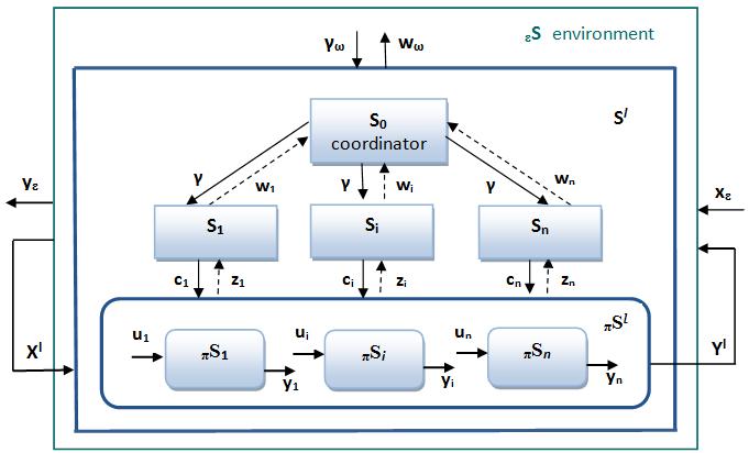
Graphical image of any level mechatronic system as aed is presented in Figure 3.1, where:
sL , sL – numerical positional system, defined on the multitude {:(,)}LI , L, L – multitude of levels indices, I – finite multitude of indices on level
S o is mechatronic object, X is input, Y is output of object S o ; – interactions of mechatronic system with other systems from its environment , and ↔ are indexes of mechatronic object , its process , process performer by MS environment , and environment itself respectively. are processes, and is the mechatronic process which object S o performs in its environment , are actions, which environment executes with object S o ;
: { 1 1
I i S S i and – families of subsystems, connected in by interconnections and correspondent sub-processes;
I i C C C i
– control signals from 1
– coordinating signals for system S ; – feedback from 0S to coordinator 1 0 S of higher level
Aed S is a system which has the following characteristic features:
– environment contains a set of systems of level ;
– it is possible to present S as object S o , its interactions with create a higher level system;
– process contains both the actions which the object S o performs in environment and actions of environment system with object S o ; – dynamic realization of S in is defined by aggregated model , , where and are aggregated dynamic models of object S o , environment and their processes , respectively;
– structure contains the lower level systems 1 S with their interactions which create coordinator 0S and in this way connect with : ~} , { 0 S , ;
– the task of coordinator 0S is to create not only systems S but also (partly) higher levels systems; for solving this task coordinator 0S constructs the informational models of concrete systems ) ( L S ; the models are constructed from the elements of interconnections of S with other systems S of level ℓ and must be coordinated both with S and higher levels systems;
incoherence of the models with concrete systems causes a change of the abstract informational model of S by coordinator 0S .
Definition 3.1. Mechatronic system S is expressed by the next aed formal system:
where is an aggregated dynamic realization of any level mechatronic system in its environment S , is a model of the system S structure, is coordinator, – index of level, , see Fig.3.1.
Fig. 3.1. Structure diagram of aed – standard block of HS. S0 is the coordinator, εS is the environment, Si are subsystems, πSi are subprocesses, πSl is the process of level , Xl and Yl are the input and output of mechatronic system Sl; ci, zi, , wi , ui, yi are interactions
3.1.1. Aggregated dynamic realization
Taking into account the necessity of creation of the external functional representation of any mechatronic object being designed, the aggregated dynamic realizations for the elements of aed construction are built in this Section. Reaction and dynamic realization of mechatronic object (MO) which is described by the ratio are constructed by the method proposed in [9]:
where is the time of level , reaction ρ, state transition function φ, and time interval tt’
Model of actions, i.e. processes which object performs in environment changing its own state differs from the model of the object:
– object of initial states of process coincides with the object of inputs ; – input of process is defined by states , their alterations are control signals to process .
Taking into account the differences, dynamic realization of mechatronic process connected with is presented in the following way:
The expression for shows that the input of object is defined not only by the environment but also (partially) by system in process , i.e. can form its inputs by itself.
Actions of environment system with the object are also formalized by dynamic system : , (3.4) , where is both the state of environment and inputs of process ; is the state of environment process , tt’ is a time interval.
Aggregated dynamic models of actions of systems and are defined as
The model of environment of system is presented as follows: , (3.6) .
The coherence condition of constructed models with concrete mechatronic systems were regarded. As stated in [9], for reaction family coherence with the time system it is necessary and enough the execution of the following conditions [9]: , (3.7) .
Time system is called a dynamic system only when it is possible to find both the reaction family and the family of the state transitions coordinated with the system, and all functions satisfy the conditions (i)–(iii) [9]:
(ii)
(iii)
The coherence conditions similar to and (3.7) for the object reaction are presented in the following way: ,(3.9) .
The conditions for , , are constructed similarly taking into account the meanings of states, inputs and outputs in the dynamic representations of processes , and environment (3.3-3.6). The meanings are
presented in Table 3.1, where and are parts of and immediately not dependant on .
Reaction families , , , are coordinated with , , and only when corresponding conditions ( 1,o 2)o , , and , which are called coherence conditions of and , are realized.
Conditions (i)-(iii) (3.8) for function of states transition are presented as follows:
o(i) , (3.10)
o(ii)
o(iii) .
Table 3.1. Connections of states, inputs and outputs for , , and
The conditions for , , are constructed similarly taking into account the meanings of states, inputs and outputs (Tab. 3.1) in the dynamic representations of , and (3.3-3.6).
So, the following qualities of the model being created and correspondent definition were formulated. If the coherence conditions of with and conditions
o((i)-(iii)) –((i)-(iii)) are realized, systems , , and are dynamic.
Definition 3.2. Set of dynamic systems { , , } connected by connections and the creating system (coordinator) are called dynamic realization of hierarchical system of any level :
Where is presented in the following form:
, and is as follows: ,
Thanks to the strong connections of components through their inputs, outputs and states, the ability of reconstructing from its parts as well as calculating unknown parts from its known ones was obtained.
The following relations are revealed. Process bonds the systems and . Dynamic realization ={ , } as well as are the relations of models and in . The difference of and models (similar to and ) is caused by the fact that the processes, i.e. actions, have their own sense in the coordination tasks described below.
With regard to the constructed dynamic realization of the system being designed, the main three tasks, which coordinator performs in are singled out:
on selection layer receives the coordination signals from higher level and forms feedback signals by the way which takes into account the running level of information uncertainty in model;
on learning layer adapts models to concrete system and makes concrete the parameters of abstract system components (removes the uncertainty);
on self-organization layer can change model and both ways of its adaptation to concrete systems and feedback signal forming, i.e. the ways of solving the tasks of choice and learning layers.
Models , and are constructed from the information about interactions of system with environment and can be obtained by coordinators , and , ( ). Therefore, coordinator of each system of level can predict changes in system and in part controls them, performing in this way the functions of coordinator of higher level .
Aggregated dynamic realization of each system is constructed from the elements of this system by the laws of level . On the other hand, is formed from connecting elements of system with environment , i.e. from the elements of other systems of level , and contains information about the individual characteristics of these systems. Therefore, begins to reflect the general laws of higher level systems and can, therefore, be regarded as a part of coordinator . In this way coordinator is connected with and continuous connection of discrete level is obtained.
3.1.2. Structure
The model of mechatronic system structure is introduced for the construction description of an object being designed. The structure is defined as follows.
Definition 3.3. The next formal system is called a structure :
and is as follows: ,(3.14) where:
0S is coordinator, are aggregated dynamic models of subsystems, , , are connections of the subsystems, . is the connection of dynamic systems and their interactions coordinated with . The dynamics of structural interconnections illustrates the dynamics of system organization from moment . Aggregated dynamic models are formed both by coordinators of systems and coordinator of a higher level, i.e. are the interlevel connections of coordinators and .
3.1.3. Coordinator
For the description of the design system and its functions in the design process the model of coordinator is constructed in this section. The first version of the model was initially described in [3] and later improved and presented in [4-8,49].
Coordinator is the main element of hierarchical systems which realizes the processes of mechatronic systems design and control. It is defined in the following form in accordance with aed representation (3.1).
Definition 3.4. The following system is called a coordinator: , (3.15) where: is aggregated dynamic realization of , is the structure of , is coordinator control element.
That is has own aggregated dynamical realization and structure . is defined recursively. Coordinator constructs its aggregated dynamic realization and structure by itself. The development of coordinator formal model on each level goes from its initial state from moment simultaneously with aed formal model development for level .
Dynamic realization of coordinator is constructed from the information about its interactions with coordinator environment :
(3.16) where is input of , is output of , are structural connections of .
With this aim, the inputs, outputs, both structural and external connections of coordinator were defined on the sets of its coordination signals and feedbacks as follows:
where: – coordination signals for systems , – feedback from , – feedback from to coordinator of higher level, – coordination signals from to .
The meanings of and were revealed. For each moment coordination signals contain the forecast of meanings of structure parameters for period : . (3.18)
Feedback signal transfers to coordinator the actual values of all the parameters of structure as well as predictions of made by the coordinators of systems of lower level:
(3.19)
It is shown, that feedback contains the analogue of coordination signals , i.e. each coordinator of lower level ℓ-1, being the part of coordinator can fulfil its functions, as stated above.
Signals and of higher level were presented just as in (3.16-3.17):
(3.20)
The availability of coordinator control element allows evaluation and changing of coordinator by itself. Let:
(3.21)
Then ; is contraction of system on the and , (3.22) , , ...
Systems are strata of coordinator and is the outlook in the level space. Structure of coordinator is presented as a multi-strata hierarchical system in agreement with [2]. Functions of each stratum are formulated as presented below.
The main design task is performed on the selection stratum when the strategies of (processes ) connect the structure dynamics and with using . Coordinator produces actual values of coordination signals , and receives feedback signals , on its selection stratum. The ways of generation and receptions of signals (coordination strategies) depend on coordinator state and state of its environment . For each way there are several levels of information uncertainty and system organization.
The information uncertainty of increases with the distance from . Every level of uncertainty on every strata has its own coordination strategy. The change of strategies is executed by learning layer (the moment it can do it) and it is controlled by the following (self-organization) stratum. At the same time the outlook in the level space extends from to . Uncertainty removal in outlook is equivalent of system organization increasing (the increasing of interactions level), when realizations are united and multiplied by , which realize the level increasing process in hierarchic space