1
International Research Journal of Engineering and Technology (IRJET) e ISSN: 2395 0056

Volume: 09 Issue: 07 | July 2022 www.irjet.net p ISSN: 2395 0072

1
International Research Journal of Engineering and Technology (IRJET) e ISSN: 2395 0056
Volume: 09 Issue: 07 | July 2022 www.irjet.net p ISSN: 2395 0072
2
Abstract - Structure analysis and design are heavily influenced by earthquakes. Seismic evaluation is deemed necessary for the quality and reliability and feasibility of existing and developing structures. Steel structures have played a vital role in the construction industry in the last few decades. It is essential to formulate a structure in such a way that it can withstand seismic loads. The seismic behaviourofa multi story steel framed building is developed in accordance with Indian code provisions (IS 800 2007). Steel bracings in the structural system will increase the ductility of the structure. Retrofitting can also make use of a variety of bracings. Steel bracings can be arranged in a variety of ways, including Braced in various ways, such as X, diagonally, alternatively, V, inverted V, K, etc. Cross bracings are used in the design of a typical multi story(G+9)steelbuildingframein this study. Using ETABS software, a static nonlinear Time History analysis is used to examine the performance of the frame. Base shear, joint displacement, kinetic energy, and story displacement are a few of the variables that affect how well a building performs during mainshock and aftershock earthquakes. Each of these variables has a significant impact on how a structure responds to seismic loads and should be considered when evaluating the results.
Key Words: Time History analysis, Cross Bracings, Steel Frame, Ground Motions, ETABS software, seismic response
Inearthquake proneareas,man madestructuresaresubject toaseismicsequencecomprisingforeshocks,themainshock, andaftershocksinadditiontoasingleseismicevent.Dueto changes in both static stress and dynamic stress that take placeduringtheearthquakeprocess,aftershockeventsare setoffbythemainshock[1].Asmallerseismiceventknown asanaftershock takesplaceinthesamegeneral area as a previouslarge earthquake. Steel bracingscan beadded to thestructuralsystemtoboostthestructure'sductility [2]. For retrofitting, various types of bracing can be utilized. Through the use of ETABS and nonlinear Time History analysis,theperformanceoftheframeisinvestigated.The near fieldearthquakegroundmotionverificationmayhave specificimpactsforbothforwardandbackwarddirectivity [3].Theinitial'svelocityanddisplacementmotions,
***
2
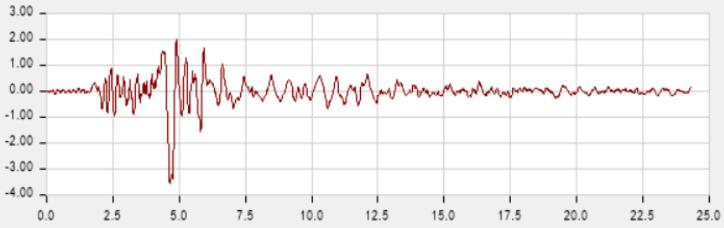
respectively, exhibit pulse and fling step characteristics. Therefore,itiscrucialtoassesshowbuildingsconstructed onlyforthepurposeofwithstandingthemainshockwould fare during subsequent aftershocks[4]. Using modern seismicprotectionsystems,suchasbaseisolationsand/or additional dampening devices, that significantly reduce building damages during main shocks and their related aftershocks is one of the appropriate solutions to this issue[5].Duetochangesinbothstaticanddynamicstress that take place during the earthquake process, aftershock eventsaresetoffbytheprimaryshock[6].Alesserseismic eventknownasanaftershocktakesplaceinthesameregion astheprimaryshockafterapreviouslargeearthquake.In ordertobetterunderstandthegroundmotionfeaturesofa sizablecollectionofmainshockandsubsequentaftershock ground motion data recorded in accelerograph stations aroundtheregion,thisstudyreviewspertinentliteraturein thefield[7].TheG+9BracedSteelFramewillbeusedinthis studytoperformtimehistoryanalysisonthemainshockand aftershockdataoftheChamoliearthquakeprovidedbythe Centre for Engineering Strong Motion Research Ground Motion Database [8]. The IS 800 2007 code is considered whendesigning.Liveloadsaremeasuredinaccordancewith IS875 part1,andseismiczoneIVisselectedforanalysisin accordance with IS 1893 2016. This paper's goal is to analysehowbracedsemi rigidsteelstructuresrespondedto apreviousearthquakesequence[9].Differentfactorswillbe consideredandexaminedforearthquakeswithmainshocks and aftershocks. Moreover we will study the seismic characteristics with Time history analysis for the same building with unscaled data provided by Centre for Engineering Strong Motion Research Ground Motion Database CHAMOLI (NW HIMALAYA) EARTHQUAKE, MARCH 29, 1999, GOPESHWAR STATION (Latitude & Longitude30’24”N 79’20”E).
International Research Journal of Engineering and Technology (IRJET) e ISSN: 2395 0056
Volume: 09 Issue: 07 | July 2022 www.irjet.net p ISSN: 2395 0072
Importancefactor 1.5
factor(I.g/R) 1.9622D planextruded
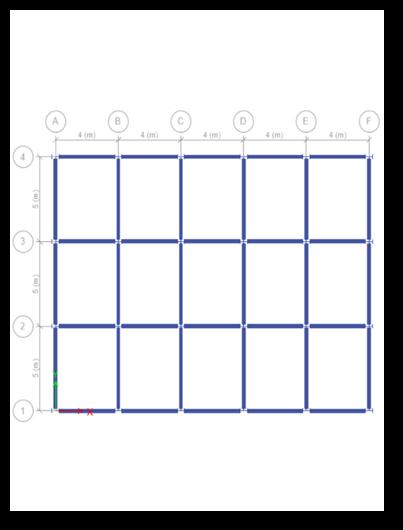
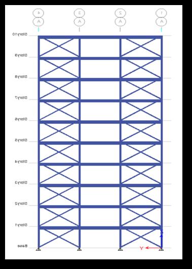
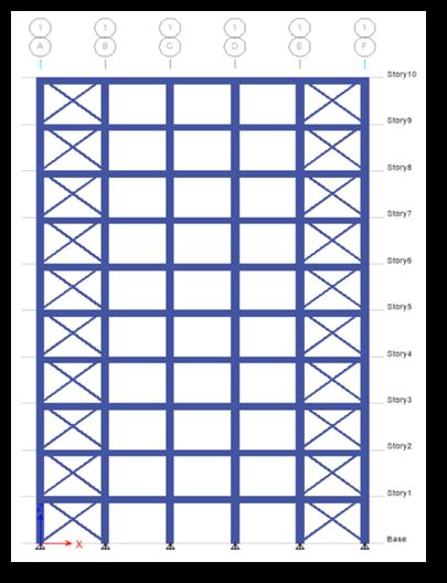
A G+9 building is modelled in ETABS v16 with a storey heightof3.1m,astructure'slengthof20minonedirection and 15 m in the other, and member sizes that vary dependingonthedesignspecifications.Theslabmeasures 150 centimetres in thickness. As per IS 800 2007 and IS 1893 2016,themodelwasevaluatedandcreated.
Table 1: propertiesofmaterial
Plandimension 20X15m2
No.ofstories 9
Floortofloorheight 3100mm
Beamsize ISWB400asperIS:800 2007
Columnsize ISHB450asperIS:800 2007 Bracing ISA150*150*15asper IS:800 2007
Gradeofsteel Fe345 DeckSize 3inches
Loadsare taken from Indianstandardcodebooks for dead loadswehaveIS875part1,forLiveloadsIS875part2and seismicanalysisisdoneaccordingtotheIS1893part12016.
Loading data Type of Load
Intensity of Load
Liveload 2kN/m2 (IS875 Part2)
SuperDead 1kN/m2 (IS875 Part1)
Seismiczone IV
Claddingload 5.0kN/m2 (IS:875 Part2)
Responsereductionfactor 5
International Research Journal of Engineering and Technology (IRJET) e ISSN: 2395 0056
Volume: 09 Issue: 07 | July 2022 www.irjet.net p ISSN: 2395 0072
Chart 2 Storey Displacement of braced Frame
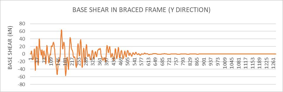
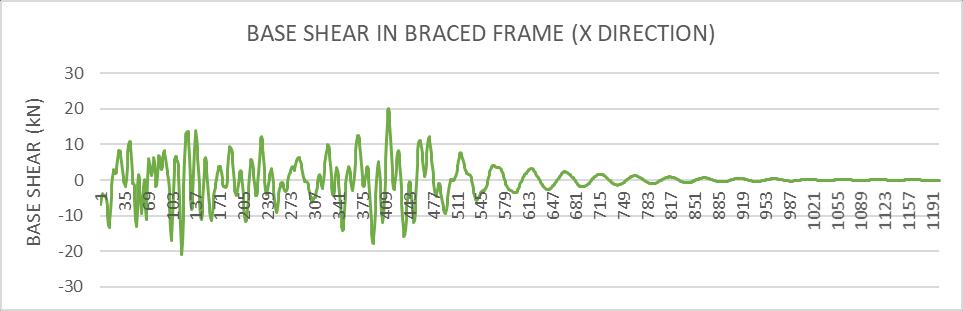
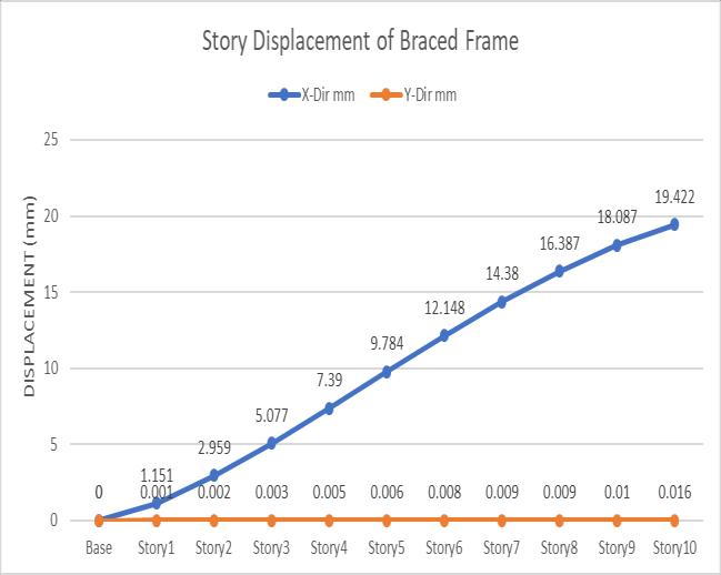
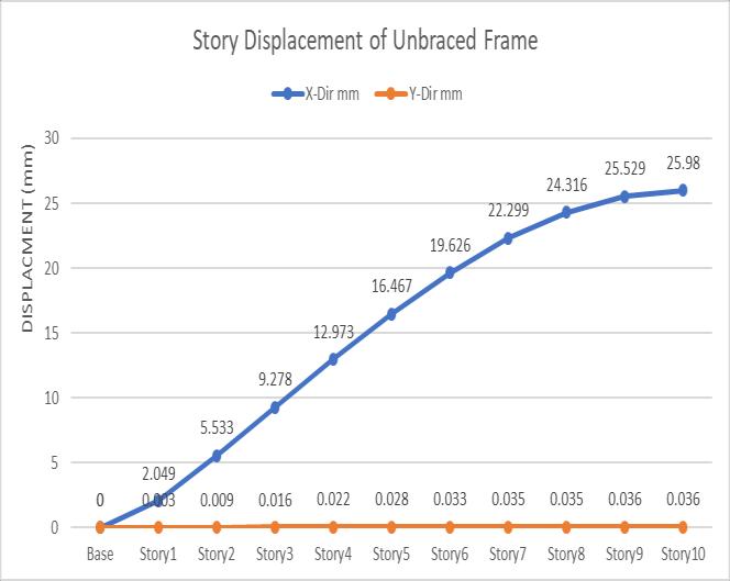
The graph displays the displacement of the tale for the braced and unbraced models. While the braced model exhibitslowerlevelsofstorydisplacementinbothaxesfor both the Mainshock and the Aftershock earthquake, both modelsexhibitbehaviorthatisessentiallythesame 5.2. Base shear (kn) of semi rigid steel frame under mainshock and aftershock earthquake data Chart
International Research Journal of Engineering and Technology (IRJET) e ISSN: 2395 0056
BASE SHEAR IN BRACED FRAME (X DIRECTION)
1000
0
-1000
2000 1 81 161 241 321 401 481 561 641 721 801 881 961 1041 1121 1201 BASE SHEAR (kN)
-2000
BASE SHEAR (kN)
BASE SHEAR IN BRACED FRAME (Y DIRECTION)
2000
1000
0
-1000
3000 1 93 185 277 369 461 553 645 737 829 921 1013 1105 1197
-2000
Chart 5: Mainshock Base shear in X direction -3000
Volume: 09 Issue: 07 | July 2022 www.irjet.net p ISSN: 2395 0072 © 2022, IRJET | Impact Factor value: 7.529 | ISO 9001:2008 Certified Journal | Page2573
International Research Journal of Engineering and Technology (IRJET) e ISSN: 2395 0056
As a result of comparison with Mainshock and Aftershock Earthquake on G+9 RC structure, following has been observed:
AsperIS1893(part1): 2002 CI. 7.11. 3,thestoreydrift inanystoreyduetotheminimumspecifieddesignlateral force, with partial load factor of 1.0, shall not exceed 0.004 times the storey height and according to the graphsobtainedthemaximumdriftis0.019418,whichis withinthepermissiblelimits[10].
5. Timehistoryanalysisisasophisticatedprogrammethat helpsyouseehowwellabuildinganditscomponents suchasthesupportingcolumns,beams,andslab are working.Bychoosinganappropriatelyselectedground motiondataofanearthquakethathasalreadyoccurred, the seismic performance of the building can be determined.
6. Crossbracingcanalsobeemployedtokeepstructures stableduringseismicoccurrenceslikeearthquakesand whenthewindblows
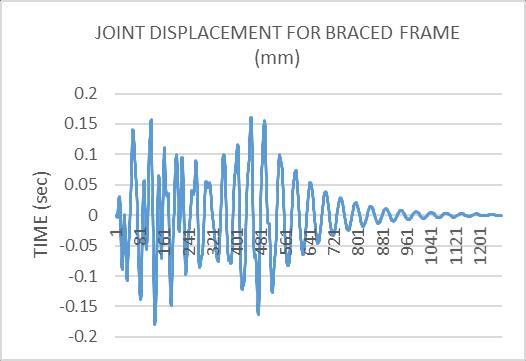
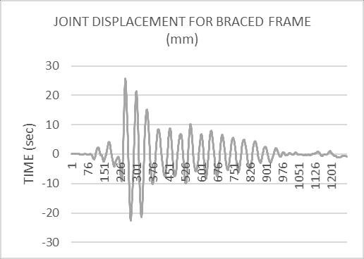
Frequency of Joint Displacement and Base Shear is greaterincaseofAftershockascomparedtoMainshock.
MaximumvalueofJointDisplacementofStorey10joint during aftershock is approx. 2 percent of joint accelerationduringMainshockforUnbracedsectionand itsapproximatelynegligibleforBracedframe.
[1] A.S.PatilandP.D.Kumbhar,“TimeHistoryAnalysisof Multistoried Rcc Buildings for Different Seismic Intensities,” Int. J. Struct. Civ. Eng. Res.,vol.2,no.3,pp. 195 201,2013.
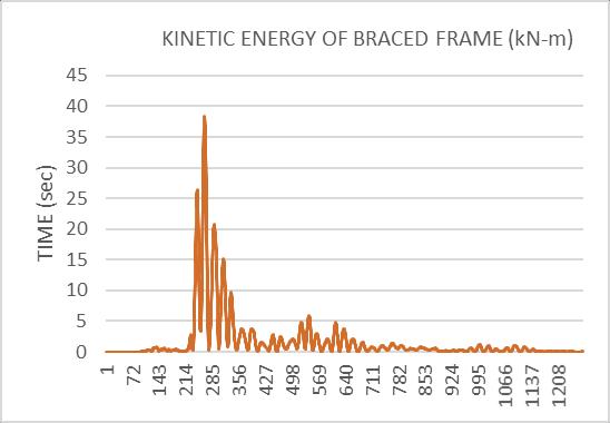
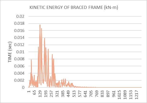
MaximumKineticEnergybuildingduringaftershockis approx.11.52percentofMaximumKineticEnergystored during Mainshock for Unbraced section and its 9.5 percentforBracedframe.
Itisobservedthatstoreydrifts,storeydisplacementand stiffness are in permissible limits as recommended by theIS1893code
Based on time history analysis, conclusions for structural framework have been established for a G+9 structure in IndiawithvarioustypesofsoilinseismiczoneIV.
1. According to the discussed results, aftershocks are unavoidableearthquakesequencesthatshouldalways be considered when building earthquake resistant structures,especiallywhenthestructurehaspreviously sustaineddamagefromafarmorepowerfulmainshock.
2. Anystructurethathasalreadyexperiencedamainshock can suffer fatal consequences from aftershocks with higher frequency and lower strength on the Richter scale.
3. The story shear starts out low at the first level of the constructionandproceedsrisingtothetopstorey.The magnitudeofstorysheargrowsalongwithabuilding's height.
4. Thebaseisolationsystem,whichseparatesthestructure (superstructure) from the base, can be supplied to prevent the mainshock and aftershock sequence (foundationorsubstructure).Theamountofenergythat is delivered towards the structure during a seismic event is greatly decreased by separating the building fromitsbase.
[2] G. B. Katti and B. S. Balapgol, “Seismic Analysis of MultistoriedRCCBuildingsDuetoMassIrregularityBy TimeHistoryAnalysis,”vol.3,no.7,pp.614 617,2014.
[3] B.LanjewarandP.A.Khedikar,“ISSNNO :0022 1945‘ Seismic Response Of RC Building Under Main shock AftershockSequence’PageNo :1409ISSNNO :0022 1945PageNo :1410,”vol.XII,no.1409,pp.1409 1419, 2020.
[4] S.KumitaniandT.Takada,“Probabilisticassessmentof buildings damage considering aftershocks of earthquakes,” J. Struct. Constr. Eng.,vol.74,no.637,pp. 459 465,2009,doi:10.3130/aijs.74.459.
[5] A. Massumi, K. Sadeghi, and H. Ghaedi, “The effects of mainshock aftershockinsuccessiveearthquakesonthe response of RC moment resisting frames considering the influence of the vertical seismic component,” Ain Shams Eng. J.,vol.12,no.1,pp.393 405,Mar.2021,doi: 10.1016/j.asej.2020.04.005.
[6] W.Huang,J.Qian,andQ.S.Fu,“DamageAssessmentof RC Frame Structures under Mainshock Aftershock SeismicSequences.”
[7] J.Ruiz GarcíaandJ.C.Negrete Manriquez,“Evaluation of drift demands in existing steel frames under as recordedfar fieldandnear faultmainshock aftershock seismicsequences,” Eng. Struct.,vol.33,no.2,pp.621 634,Feb.2011,doi:10.1016/j.engstruct.2010.11.021.
[8] J. Ruiz García, “Issues on the Response of Existing Buildings Under Mainshock Aftershock Seismic Sequences.”
Volume: 09 Issue: 07 | July 2022 www.irjet.net p ISSN: 2395 0072 © 2022, IRJET | Impact Factor value: 7.529 | ISO 9001:2008 Certified Journal |
[9] A. Ilyas, M. A. Azeem, and H. Mohiuddin, “seismic response of reinforced concrete buildings under mainshock Aftershockearthquakesequence,” Int.J.Civ. Eng. Technol.,vol.9,no.4,pp.647 659,2018.
[10] S. D. V. M. V Waghmare, “Nonlinear Analysis of RC Structure under Multiple Earthquakes,” vol. 5, no. September,2019unpublished.
International Research Journal of Engineering and Technology (IRJET) e ISSN: 2395 0056 Volume: 09 Issue: 07 | July 2022 www.irjet.net p ISSN: 2395 0072 © 2022, IRJET | Impact Factor value: 7.529 | ISO 9001:2008 Certified Journal | Page