Under the guidance of Mr. Sonu Navgotri4 Assistant Professor Department of Mechanical Engineering Rewa Engineering College Rewa(m.p.)
Abstract This research paper is about Design and analysis of Roll Cage of an ATV (acronym for ALL TERRAIN VEHICLE).Itis oneof the mainsystems ofthe ATV on which the other subsystems like Engine, Steering, and Transmission systems, seat, suspension systemsetcaremounted.Itcomesunderthespringmass system of the vehicle. The forces acting on the vehicle from different directions are accountable for the breakdown and deformation in the vehicle. Therefore, the stresses are generated viz maximum combined stresses,minimumcombinedstresses,directstressesetc in this paper we have made an attempt to figure out theseareasbydoingcrashtestsoftherollcagedesigned on CATIA V5. We have carried out crash analysis (front, rear,sideimpact,rollover,Bump)andtorsionalanalysis. AlltheseanalyseshavebeencarriedoutinANSYS R21.0 academic version. The design procedure follows all the ruleslaiddownbySAErulebookforBajaATV2021
International Research Journal of Engineering and Technology (IRJET) e-ISSN: 2395-0056 Volume: 09 Issue: 03 | Mar 2022 www.irjet.net p ISSN: 2395 0072 © 2022, IRJET | Impact Factor value: 7.529 | ISO 9001:2008 Certified Journal | Page667 DESIGN, ANALYSIS AND MANUFACTURING OF SAE INDIA BAJA ATV ROLLCAGE Abhishek Pandey1, Ayush Nigam2, Saumya Singh Tiwari3

For a finer performance of an ATV, it is very crucial to make sure that all elements work as per the planned design calculations. Being an important system roll cage absorbs all the static and dynamic loads, the structure should be such that it can withstand the stresses generated without getting damaged. different forces from different directions act on the vehicle when it is in static or in dynamic situation. These forces cause deformation which results in stress generation at differentpointsoftherollcage.Thestiffnessfactorofthe roll cage should be able to resist these forces. The primary function of roll cage is to absorb all the loads from the suspension with minimum deformation and secondaryisthatitshouldactasamountingmemberfor all the other components on the vehicle. The final and most vital function of it is that it must have more continuous members to distribute the stresses and high torsional stiffness to resist the forces during the competition. The roll cage is made by joining seamless tubes welded together. First a proper design of the roll cageistobemadebytakingdesireddimensionsfromas mentioned in the rulebook of SAE India Baja 2021. The pipes are then formed into desired dimensions by cuttingandbending.thereafternotchingisdoneonthese pipes. Finally, the pipes are welded together to form a rollcage.
4
Key Words:Rollcage,FiniteElementAnalysis,Strength, Factorofsafety
MATERIALS AND METHODS:
INTRODUCTION:
1 3B. tech in Mechanical Engineering Rewa Engineering College Rewa (M.P.)
Material of sufficiently higher yield strength should be selectedtomaintaintheoptimumlevelofstressesinthe rollcage.Herethestrengthofthematerialespeciallythe ultimate yield strength plays a crucial role. The factors affectingtheselectionofthematerialareasfollows: 1. The stresses generated and the factor of safety of the rollcage. 2. The allotments given to other elements (or components)tobemountedontherollcage. The factor of safety (FOS) plays a significant role, it is definedastheratiooftheultimateyieldstrengthtothat of the stresses generated in the roll cage. This value of factorofsafetyfortherollcagemustnotbegreaterthan 3andlessthan1.Ifthevalueislessthan1,itwillleadto a significant deformation before reaching the maximum stress value. If the value is greater than 3, then the weight of roll cage will cross the optimum level up to which it should have to be. The vehicle is supposed to perform in various situations such as muddy and off roadterrainconditions.Theelementsofrollcageneedto be either welded or nut bolted. Thus, the material selected must be weldable. Thus, we need a material which has high strength, stiffness and is weldable. considering these requirements, the material selected is AISI4130Alloysteel.
***
FRAME DESIGN:
TheRoll cageisdesignedconsideringmanyfactorssuch as cross sectional area of the pipes, front impact force, side impact force, rollover, tortional impact, bump impact forces the vibrations caused by other components while running of the vehicle and vibrations causedbytheengineetc. Thecrosssectionismandatorytobeselectedascircular tube as it was already mentioned in the rulebook. The outer diameter and thickness of the cross section of circulartubesintheprimary andsecondarymembersof roll cage are 25mm and 3mm respectively. The values aretakenaspertherulebookofsaeIndiaBaja2021. Area Moment of Inertia I=(π/64)x(D4 d4) =( =1.27x BENDING STRENGTH: = :Y=D/2 =405.3320505 BENDING STIFFNESS: =EXI =2.05X X1.27X =2603.5
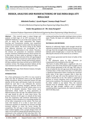
Considering SAE India Baja Rulebook 2021 as the guide book for extracting all the dimensions, and constraints requiredtomaketheroll cage,andthenusingCATIAv5 software the wireframe of the model is designed as shownintheimagebelow.
6. Then in static structural workbench after applying all the necessary loads and constraints do all the analysisviz, frontimpactanalysis rearimpactanalysis sideimpactanalysis rolloverimpactanalysis bumpimpactanalysis tortionalimpactanalysis
METHODOLOGY
MODELLING
Journal | Page668 Table 1:
1. Creation of a wireframe of the structure in the CATIAV5software. 2. Giving it cross section by importing it on design modellerofAnsysR21.0ACADEMICS
Volume: 09 Issue: 03 | Mar 2022 www.irjet.net p ISSN: 2395 0072 © 2022, IRJET | Impact Factor value: 7.529 | ISO 9001:2008 Certified
Fig1: wireframe model of the Roll cage.
International Research Journal of Engineering and Technology (IRJET) e-ISSN: 2395-0056
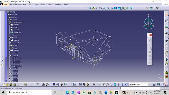
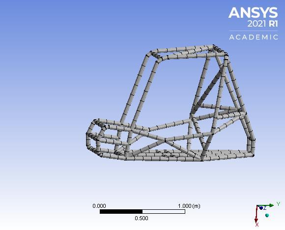
Fig2: Isometric View of the roll cage model.
5. After setting all the analysis and frequency setting calculatetotaldeformation.
8.Repeatthesameprocessuntilyougetthesafedesign. We have selected 1D meshing for analysis of Roll Cage bytakingconsiderationoffactorwhicharegivenbelow properties metric TensileStrength 750MPa Yieldstrength 650MPa Elongation 25.5% Modulusofelasticity 205GA Density 750kg/m^3 Percentageofcarbon 0.28%
3. Doing the normal modal analysis to check weather eachelement of the roll cageis perfectlyconnected ornot 4. Generationofmeshinmechanicalmodeller
7. Then modify the wireframe CAD model to get minimumdeformationvalues.
Volume: 09 Issue: 03 | Mar 2022 www.irjet.net p ISSN: 2395 0072 © 2022, IRJET | Impact Factor value: 7.529 | ISO 9001:2008 Certified Journal | 669
FINITE ELEMENT ANALYSIS (FEA): ThisFEAsoftware(inourcaseAnsysR21.0ACADEMICS) is used to highlight the failure and stress concentration in the design before going into manufacturing and also showswhetheraproductwilldamage,wearout,orwork the way it is designed or not. Therefore, the cost of manufacturing can be optimized. Here depending upon the element size the roll cage is divided into small elementscallednodestoformaperfectmeshsothatthe results obtained will be more accurate. To finalize the material and structure of roll cage FEA was performed onitontheaforementionedsoftware
1.Mostaccurate sopreferable 2.Levelofassumptionsisverylessas comparedtoothertypesofmeshing 3.Giveresultsonjointsquickly. 4 Outputs received are total deformation, direct stress, maximumcombinedstress,minimumcombinedstress. 5. Only cross section of pipe is required to give as circulartubes
International Research Journal of Engineering and Technology (IRJET) e-ISSN: 2395-0056
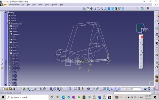
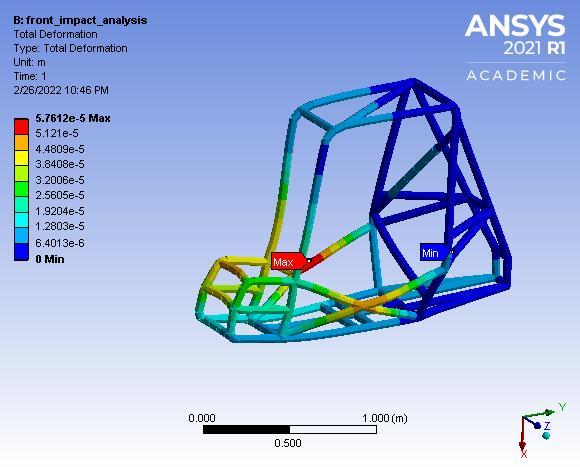
1. FRONT IMPACT ANALYSIS: The front impact analysis is done in an assumption that when the impact will occur at the front part of the ATV the stresses will be generated at the front part, so the deformation is observed. By those results it will be easy to analyse that whether this roll cage can withstand to that impact or not. The crash analysis has been performed in Ansys 21.0 ACADEMICS
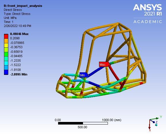
Fig5: Total deformation
Fig6: Direct Stress
Page
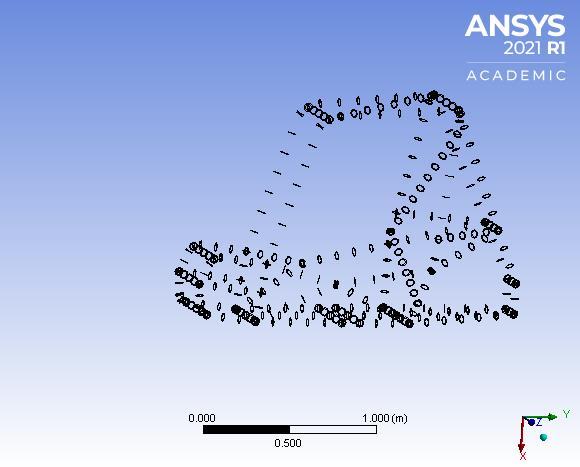
Fig3: meshed model of the roll cage of ATV Fig 4: nodes on Roll cage
Theversionnodal displacement and nodal rotation are kept fixed for rear suspension mountings and forces are applied on front side of the roll cage, in suspension mountings nodal rotations are kept fixed and nodal displacement for perpendicularly downward directioniskept0
Following test were performed on the roll cage: 1. FrontImpactAnalysis 2. RearimpactAnalysis 3. SideImpactAnalysis 4. TortionalImpactAnalysis 5. RollOverImpactAnalysis 6. BumpImpactAnalysis
Themeshedmodeloftherollcageandnumberofnodes areshowninimagesbelow:
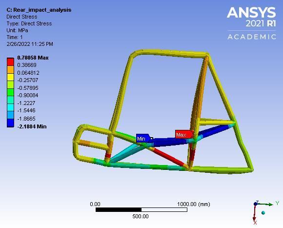
The rear impact analysis is done in an assumption that when the impact will occur at the rear part of the ATV, thestresseswillbegeneratedattherearpartsothatthe deformation can be observed and analysed. By those results it will be easy to manipulate that whether this roll cage can withstand to that impact or not. The crash analysis has been performed in Ansys 21.0 ACADEMICS Allworkbench.thetranslational and rotational degrees of freedom are kept fixed on the front side of the Roll Cage and forcesareappliedonrearsideofrollcage,insuspension mountings nodal rotations are kept fixed and nodal displacementforperpendicularlydownwarddirectionis kept0(+xdirectioninourcase).
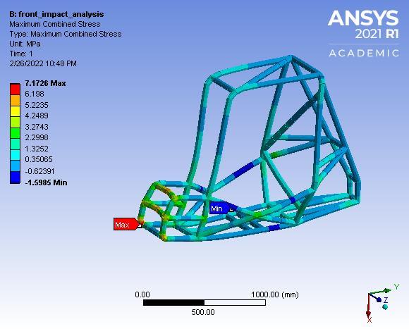
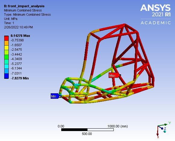
International Research Journal of Engineering and Technology (IRJET) e-ISSN: 2395-0056 Volume: 09 Issue: 03 | Mar 2022 www.irjet.net p ISSN: 2395 0072 © 2022, IRJET | Impact Factor value: 7.529 | ISO 9001:2008 Certified Journal | Page670 Fig7: Minimum Combined Stress Fig8: Maximum Combined Stress BOUNDARY CONDITIONS Thetotalweightoftherollcageis consideredas260kg. Initialvelocity=50km/hr. Finalvelocity=0km/hr. Impacttime=0.376seconds W=W=W=25045.07Nm Displacement=VXT S=S=5.135m Force = W/S= 4877.32m RESULTS: Totaldeformation=0.057612mm Directstress=0.49846MPa Maximumcombinedstress=7.1726MPa MinimumCombinedStress=0.14276MPa Hence,thedesignissafe.
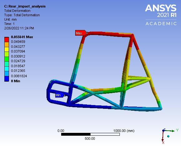
2. REAR IMPACT ANALYSIS
Fig9: Total Deformation Fig10: Direct Stress
International Research Journal of Engineering and Technology (IRJET) e-ISSN: 2395-0056 Volume: 09 Issue: 03 | Mar 2022 www.irjet.net p ISSN: 2395 0072 © 2022, IRJET | Impact Factor value: 7.529 | ISO 9001:2008 Certified Journal | Page671 Fig11: Minimum Combined Stress Fig12: maximum Combined Stress Boundary Conditions: TotalVehicleweightisconsideredas260kg Initial velocity of the vehicle = 50.1 km/hr = 13.88m/s Finalvelocity=0km/hr. Impacttime=0.376seconds W=W=W=25045.07 Displacement=NmVXT S=S=5.135m Rear impact Force = W/S= 4877.32m RESULTS TotalDeformation=0.055641mm Directstress=0.70858MPa MaximumCombinedStress= Min5.0751MPaimumCombinedStress=0.4661MPa
Fig13: Total Deformation Fig14: Direct Stress Fig15: Minimum Combined Stress
3. SIDE IMPACT ANALYSIS
The side impact analysis is done in an assumption that when the impact will occur at the side members of the ATV (i.e., SIM members), the stresses will be generated at the side part so that the deformations can be observed. By those results it will be easy to manipulate then that whether this roll cage can withstand to that side impact or not. The crash test is done on Ansys 21.0 ACADEMIC workbench. All the translational and rotational degrees of freedom are kept fixed for front andfappliedonlyonthesidemembers.
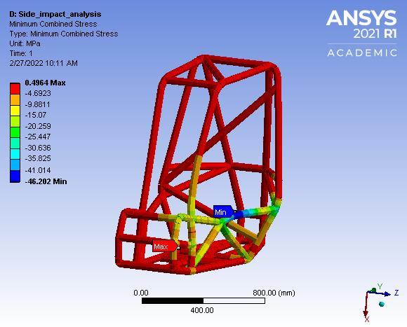
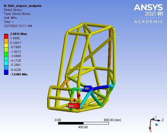
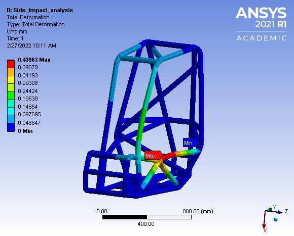
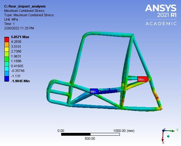
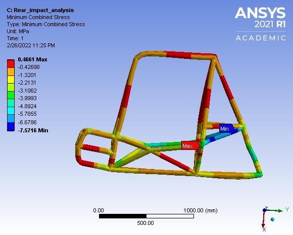
Fig17: Total Deformation Fig18: Direct Stress Fig19: Minimum Combined Stress Fig20: Maximum Combined Stress
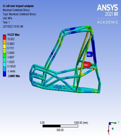
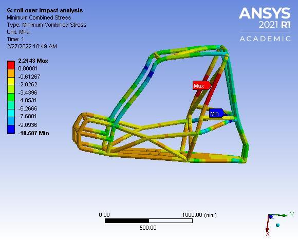
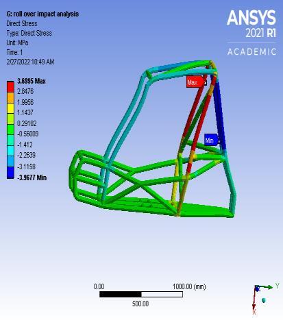
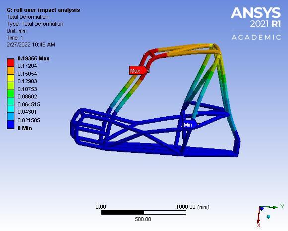
4. ROLL OVER IMPACT ANALYSIS Inrolloverimpacttesting,itisobservedthatweatherall the members associated with the RHO members along withdiagonalmembersareableenoughtheloadsornot. This analysis is done in Ansys 21.0 R1 ACADEMIC workbench. All the degrees of freedom on the front and rearsuspensionmountingsarekeptfixedandforcesare applied on the front bracing members and RHO membersbyintroducinganewcoordinatesysteminthe workbench
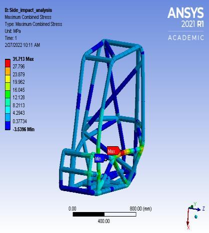
International Research Journal of Engineering and Technology (IRJET) e-ISSN: 2395-0056 Volume: 09 Issue: 03 | Mar 2022 www.irjet.net p ISSN: 2395 0072 © 2022, IRJET | Impact Factor value: 7.529 | ISO 9001:2008 Certified Journal | Page672 Fig16: Maximum Combined Stress Boundary conditions: The weightof the roll cageisconsideredas260 Allkg the nodes on the front and rear suspension mountings for nodal displacements and nodal rotationarekeptfixed. Forcesareappliedonthesidemembers. Initialvelocity=50km/hr=13.88m/s Impacttime=0.376s Finalvelocity=0m/s Decelerationitwillgoon: ==13.88/0.376=36.914 ==Force:=ma9597.64N RESULTS: Totaldeformation=0.43963mm Directstress=2.5815MPa Maximumcombinedstress=31.713MPa Minimumcombinedstress=0.4964MPa The values are optimum and the design is safe forsideimpact.
Weightdistribution: Weightonfrontaxle =0.6 =1530N Torsional force= 1530N Calculation for torsional stiffness: Rollcageweight=50.1Kg Carweight=260Kg Force(F)=1530N Trackwidth=1320.8mm
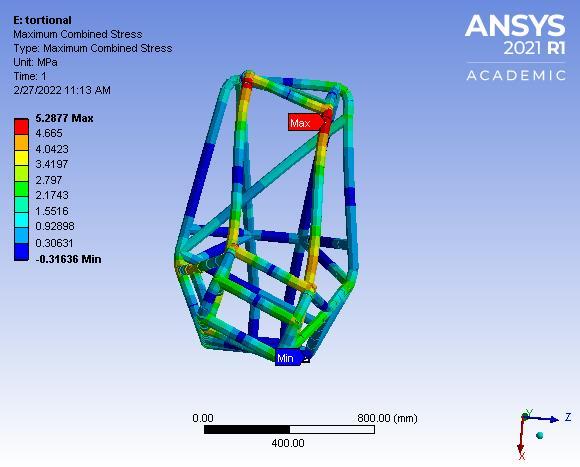
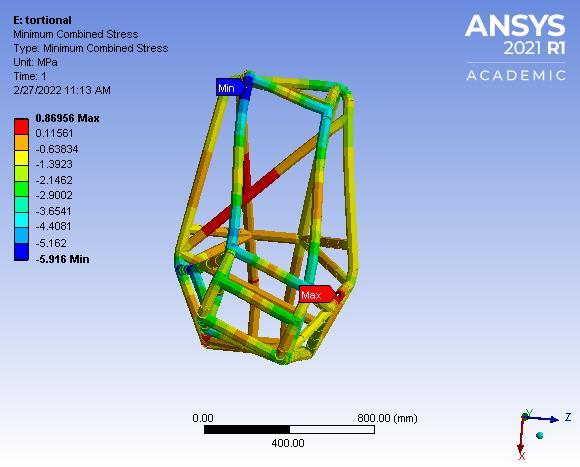
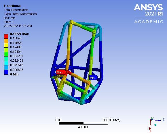
Torsional analysis is used to analyse the torsionalstiffnessoftherollcagei.e.,howmuch the structure can resist the twisting. It is very important parameter of any vehicle to resist torsional stress and deflection during the turning, drifting, cornering and undulating road surface. So, the ATV should have high torsional stiffness so it can withstand bending in any Translationaldirection. and rotational degreesoffreedom for rear suspension mountings are kept fixed andinthefrontsuspension mountingstheright and left members are applied with equal forces inoppositedirection. Fig21: TotalDeformation
Boundary condition: weight of the Roll cage is considered to be impact260kg.time=0.17sec ATVdroppedfromheight=1.75m Height= Potential1.75menergy=kineticenergy Mgh= √ √ | | DisplacementS=v m F=W/s= F= RESULT4500NS: Totaldeformation=0.19355mm Directstress=3.6995MPa Minimumcombinedstress=2.2143MPa Maximumcombinedstress=11.637MPa Hence the design is safe in the roll over impact analysis
International Research Journal of Engineering and Technology (IRJET) e-ISSN: 2395-0056
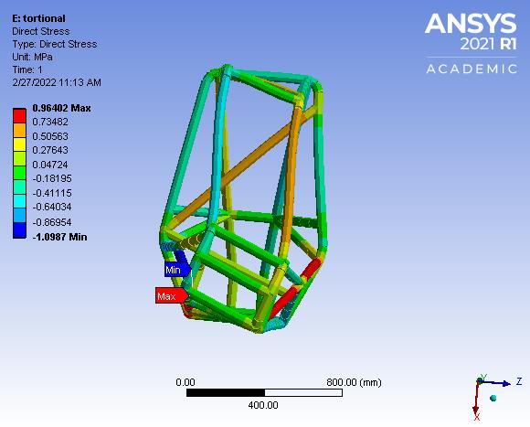
5. TORTIONAL IMPACT ANAYSIS
Certified Journal | Page
Fig22: Direct stress Fig23: Minimum Combined Stress Fig24: Maximum Combined Stress
Volume: 09 Issue: 03 | Mar 2022 www.irjet.net p ISSN: 2395 0072 © 2022, IRJET | Impact Factor value: 7.529 | ISO 9001:2008 673
Boundary conditions: Weightoftherollcageisconsideredas260kg Impacttime=0.376s
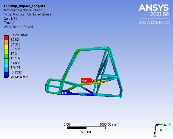
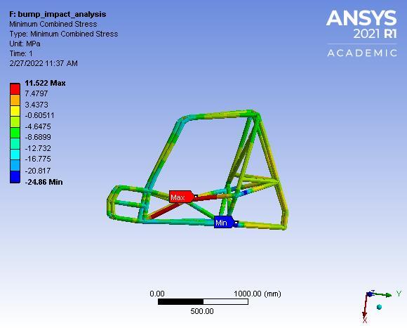
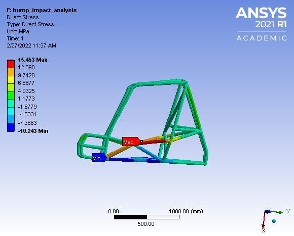
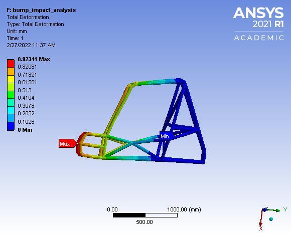
International Research Journal of Engineering and Technology (IRJET) e-ISSN: 2395-0056 Volume: 09 Issue: 03 | Mar 2022 www.irjet.net p ISSN: 2395 0072 © 2022, IRJET | Impact Factor value: 7.529 | ISO 9001:2008 Certified Journal | Page674 Torque = F× ( )×track width = 1530× ( )×1.3208=1010.412N m θ = Angle of deflection = ( ) = ( = =Tortional0.0162stiffness =9444.44=1530/0.0162Nm/degree RESULS: Totaldeformation=0.18727mm Directstress=0.96402MPa Minimumcombinedstress=0.86956MPa Maximumcombinedstress=5.2877MPa 6. BUMP IMPACT ANALYSIS: All the translational and rotational Degrees of freedom of rear suspension mountings are kept fixed and forces are applied on right and left front suspension mountings in downward direction. Fig25: Total Deformation Fig26: Direct Stress Fig27: Minimum Combined Stress Fig28: Maximum Combined Stress Boundary condition: Weightoftherollcage=260kg Radiusofbump=17m Speed=20km/hr=5.55m/s Massofpassenger=75kg Bump force: F= +mg =871.64=N RESULTS: Totaldeformation=0.92341mm Directstress=15.453MPa Minimumcombinedstress=11.522MPa Maximumcombinedstress=37.733MPa 7. FEA ANALYSIS RESULT:Table 2: sanalysiMetric/- FIA RIA SIA IARO TIA BIA TD 27610.05 15640.05 33960.4 59350.1 78720.1 12340.9 DS 0.49 0.70 2.5 3.6 0.9 15.
References:SAEIndiaBajaRulebook2021 KodavantiVRSNMurthyDesignandanalysisof BAJArollcage e ISSN: 2395 0056 Volume: 07 Issue: 03 | Mar 2020 international research journal on science andtechnology p ISSN:2395 0072 CATIAv5andANSYSAPDLR21.0ACADEMIC AmitRParateDesignandfabricationofrollcage international research journal on research and etechnologyISSN:2395 0056 Volume: 05 Issue: 07 | July 2018p ISSN:2395 0072
International Research Journal of Engineering and Technology (IRJET) e-ISSN: 2395-0056
Volume: 09 Issue: 03 | Mar 2022 www.irjet.net p ISSN: 2395 0072 © 2022, IRJET | Impact Factor value: 7.529 | ISO 9001:2008 Certified Journal | Page675 846 858 815 995 2640 453 MiCS 267.17 515.07 71331. 1432.2 66950.8 52211. MaCS 2760.14 610.46 9640.4 63711. 5775.2 73337.
Theuseoffiniteelementanalysis wasprovedtobevery useful for the design of our roll cage for SAE India BAJA all terrain vehicle (ATV). We successfully analysed the roll cage for its strength against the impacts from front, rear,side,tortional,rolloverandbumpimpacts. This paper describes in detail with various impact analysis on the roll cage and optimization is brought by reducingtheweightofit Thedesignisperfectforusein theeventwithallthesystemsperfectlymountedonit
CONCLUSION
