1 minute read
Outputs received are total deformation, direct stress maximum combined stress, minimum combined stress.


1. Most accurate –so preferable 2.Level of assumptionsis very lessas compared to othertypes ofmeshing 3. Give results on jointsquickly. 4. Outputs received are total deformation, direct stress, maximum combined stress, minimum combined stress. 5. Only cross section of pipe is required to give as circular tubes.
FINITE ELEMENT ANALYSIS (FEA):
Advertisement
This FEA software(in our case Ansys R21.0 ACADEMICS) is used to highlight the failure and stress concentration in the design before going into manufacturing and also shows whether a product willdamage,wear out, or work the way it is designed or not. Therefore, the cost of manufacturing can be optimized. Here depending upon the element size the roll cage is divided into small elementscalled nodesto form a perfect mesh so that the results obtained will be more accurate. To finalize the material and structure of roll cage FEA was performed on iton the aforementioned software.
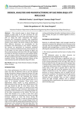
The meshed model of the roll cageand number of nodes are shown in imagesbelow: -
Fig3: meshed model of the roll cage of ATV

Fig 4: nodes on Roll cage
- Following test were performed on the roll cage: 1. Front Impact Analysis 2. Rear impact Analysis 3. Side Impact Analysis 4. Tortional Impact Analysis 5. Roll Over Impact Analysis 6. Bump Impact Analysis
1. FRONT IMPACT ANALYSIS: The front impact analysis is done in an assumption that when the impact will occur at the front part of the ATV the stresses will be generated at the front part, so the deformation is observed. By those results it will be easy to analyse that whether this roll cage can withstand to that impact or not. The crash analysis has been performed in Ansys 21.0 ACADEMICS version.
The nodal displacement and nodal rotation are kept fixed for rear suspension mountings and forces are applied on front side of the roll cage, in suspension mountings nodal rotations are kept fixed and nodal displacement for perpendicularly downward direction is kept 0

Fig5: Total deformation