1.1 TYPES OF TURBINES 1. GasTurbine 2. SteamTurbine 3. Shrouded Turbine 4. Shrouded LessTurbine
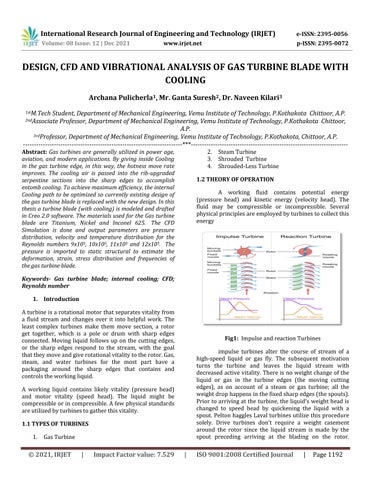
Fig1: ImpulseandreactionTurbines impulse turbines alter the course of stream of a high speed liquid or gas fly. The subsequent motivation turns the turbine and leaves the liquid stream with decreasedactivevitality.Thereis no weightchange of the liquid or gas in the turbine edges (the moving cutting edges), as on account of a steam or gas turbine; all the weightdrophappensinthefixedsharpedges(thespouts). Priortoarrivingattheturbine,theliquid's weightheadis changed to speed head by quickening the liquid with a spout.Pelton hagglesLaval turbinesutilize thisprocedure solely. Drive turbines don't require a weight casement around the rotor since the liquid stream is made by the spout preceding arriving at the blading on the rotor.
***
Keywords- Gas turbine blade; internal cooling; CFD; Reynoldsnumber 1. Introduction Aturbineisarotationalmotorthatseparatesvitalityfrom a fluid stream and changes over it into helpful work. The least complex turbines make them move section, a rotor get together, which is a pole or drum with sharp edges connected. Moving liquid follows up on the cutting edges, or the sharp edges respond to the stream, with the goal thattheymoveandgiverotationalvitalitytotherotor.Gas, steam, and water turbines for the most part have a packaging around the sharp edges that contains and controlstheworkingliquid. A working liquid contains likely vitality (pressure head) and motor vitality (speed head). The liquid might be compressibleorincompressible.Afewphysicalstandards areutilizedbyturbinestogatherthisvitality.
Archana Pulicherla1 , Mr. Ganta Suresh2 , Dr. Naveen Kilari3
A working fluid contains potential energy (pressure head) and kinetic energy (velocity head). The fluid may be compressible or incompressible. Several physicalprinciplesareemployedbyturbinestocollectthis energy
3rdProfessor, Department of Mechanical Engineering, Vemu Institute of Technology, P.Kothakota, Chittoor, A.P.
International Research Journal of Engineering and Technology (IRJET) e ISSN: 2395 0056 Volume: 08 Issue: 12 | Dec 2021 www.irjet.net p ISSN: 2395 0072 © 2021, IRJET | Impact Factor value: 7.529 | ISO 9001:2008 Certified Journal | Page1192
Abstract: Gas turbines are generally utilized in power age, aviation, and modern applications. By giving inside Cooling in the gas turbine edge, in this way, the hotness move rate improves. The cooling air is passed into the rib upgraded serpentine sections into the sharp edges to accomplish entomb cooling. To achieve maximum efficiency, the internal Cooling path to be optimized so currently existing design of the gas turbine blade is replaced with the new design. In this thesis a turbine blade (with cooling) is modeled and drafted in Creo 2.0 software. The materials used for the Gas turbine blade are Titanium, Nickel and Inconel 625. The CFD Simulation is done and output parameters are pressure distribution, velocity and temperature distribution for the Reynolds numbers 9x10⁵, 10x105, 11x105 and 12x105. The pressure is imported to static structural to estimate the deformation, strain, stress distribution and frequencies of the gas turbine blade.
1.2 THEORY OF OPERATION
DESIGN, CFD AND VIBRATIONAL ANALYSIS OF GAS TURBINE BLADE WITH COOLING
1stM.Tech Student, Department of Mechanical Engineering, Vemu Institute of Technology, P.Kothakota Chittoor, A.P.
2ndAssociate Professor, Department of Mechanical Engineering, Vemu Institute of Technology, P.Kothakota Chittoor, A.P.


International Research Journal of Engineering and Technology (IRJET) e ISSN: 2395 0056 Volume: 08 Issue: 12 | Dec 2021 www.irjet.net p ISSN: 2395 0072 © 2021, IRJET | Impact Factor value: 7.529 | ISO 9001:2008 Certified Journal | Page1193
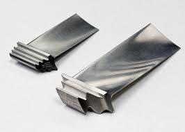
Fig 3: Turbinecooling 1.6 Convection cooling
Newton'ssubsequentlawportraystheexchangeofvitality formotivationReactionturbines.turbines create force by responding to thegasorliquid'sweightormass.Theweightofthegasor liquidchangesasitgoesthroughtheturbinerotoredges.A weightcasementisexpectedtocontaintheworkingliquid asitfollowsupontheturbinestage(s)ortheturbinemust becompletelydrenchedintheliquidstream,(forexample, with wind turbines). The packaging contains and coordinates the working fluid and, for water turbines, keeps up the attractions conferred by the draft tube. Francisturbinesandmoststeamturbinesutilizethisidea. For compressible working liquids, various turbine stages are typically used to bridle the growing gas effectively. Newton's third law depicts the exchange of vitality for Reactionturbines.
The sort of activity for which the motor is structured directs the presentation necessity of a gas turbine motor. The exhibition prerequisite is for the most part dictated by the measure of shaft torque (s.h.p.) the motorcreatesforagivenarrangementofconditions.Most of airplane gas turbine motors are appraised at standard day states of 59 0F and 29.92 inches Hg. This gives a pattern to which gas turbine motors of numerous kinds canbethoughtabout. The requirement for high productivity in the motor turns outtobeincreasinglysignificantaspowersbecomeallthe more expensive. Motor effectiveness is principally characterizedbytheparticularfuelutilization(s.f.c.)ofthe motoratagivenarrangementofconditions
1.4 INTRODUCTION TO TURBINE BLADE
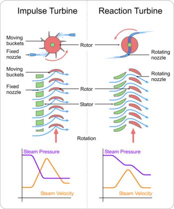
Fig 2:TurbineBlades 1.5 TURBINE BLADE COOLING
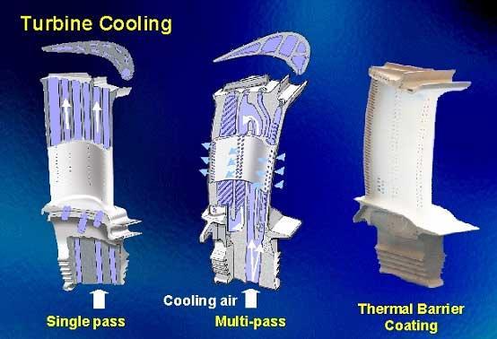
Another strategy to improving turbine blades and increasing their operating temperature, aside from better materials,istocooltheblades.Therearethreemaintypes ofcoolingusedingasturbineblades;convection,film,and transpiration cooling. While all three methods have their differences, they all work by using cooler air (often bleed from the compressor) to remove heat from the turbine blades.
A turbine blade is the individual segment which makes up the turbine segment of a gas turbine. The sharp edgesareanswerable forseparatingvitalityfrom thehigh temperature, high weight gas delivered by the combustor. The turbine cutting edges are regularly the constraining segment ofgasturbines.To makedue in thistroublesome condition, turbine cutting edges regularly utilize extraordinary materials like superalloys and a wide range oftechniquesforcooling, forexample, insideairchannels, limitlayercooling,andwarmobstructioncoatings.
1.3 PERFORMANCE AND EFFICIENCY
Convection cooling works by going cooling air through entries inward to the edge. Warmth is moved by conductionthroughtheedge,andafterwardbyconvection into the air streaming within the edge. A huge inward surface region is alluring for this strategy, so the cooling ways will in general be serpentine and brimming with littlebalances.


BasedontheNACA6412coordinatepoints,a freesmooth curveisdrawnwhichindicatedtheclosedloopprofile
The gas turbine blade is developed in 3D modelling software and then converted into igs format. This format is imported to CFD and then applied Pressure 32364kPa,Temperature1500°Cfortheoutersurface
International Research Journal of Engineering and Technology (IRJET) e ISSN: 2395 0056 Volume: 08 Issue: 12 | Dec 2021 www.irjet.net p ISSN: 2395 0072 © 2021, IRJET | Impact Factor value: 7.529 | ISO 9001:2008 Certified Journal | Page1194 Fig 4: FilmandConvectioncooled.
3D MODELING OF GAS TURBINE BLADE
2. LITERATURE SURVEY InthispaperbyOmidAskari[1],CoolingofTurbineBlade Surface WithExtendedExit Holes.Theturbinesharp edge surface is cooled by stream from expanded exit holes (EEH). Cooling viability is characterized as temperature difference(TD)betweenthehotgasstreamandthecutting edgesurfaceasasmallamountoftemperaturedistinction betweenthehotgasstreamandthecoolantmovethrough EEH. Computational exploration utilizing a business code has been done to foresee the presentation of EEH for an alternate structure and working conditions. Viability has beenresolvedoverthesharpedgesurfacewhengeometric conditions, for example, the point among EEH and edge surface, area of EEH on the cutting edge surface and exit to throat region proportion of EEH. Anticipated viability dispersions concur well with accessible exploratory outcomes, affirming value and preferred position of a computational way to deal with enhancing turbine sharp edge cooling with EEH. In this paper by Fariborz Forghan[2], Film Cooling of Turbine Blade Surface With Extended Exit Holes. The fundamental objective of gas turbineconfigurationisthepowerfulutilizationofvitality. Ordinarily, the proficient high temperature first and second stage turbine sharp edge surface is cooled by a stream of coolant stream from expanded leave openings (EEH). Against the predominant hot gas stream, the move through EEH must be intended to frame a film of cool air over the sharp edge. Computational examinations are performed to analyze the cooling viability of stream from EEH over the attractions side of a sharp edge by illuminating preservation conditions (mass, force and vitality) and the perfect gas condition of state for the three dimensional, tempestuous, compressible stream. A separating move through EEH is normally gagged at its throat, bringing about a supersonic stream, a stun and afterward a subsonic stream downstream. The area of the stun comparative with the high temperature gas stream over the cutting edge decides the temperature disseminationalongtheedgesurface;whichisdissectedin detailwhenthecoolantstreamrateisfluctuated.
Fig 5: NACA2Dprofile
Figure 6: (a)heightofthegasturbineblade(b)complete 3Dmodeloftheoriginalgasturbineblade(c)coolingribs totheblade.
Fig 7:Crossectionalview CFD Simulation

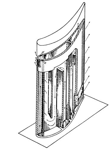
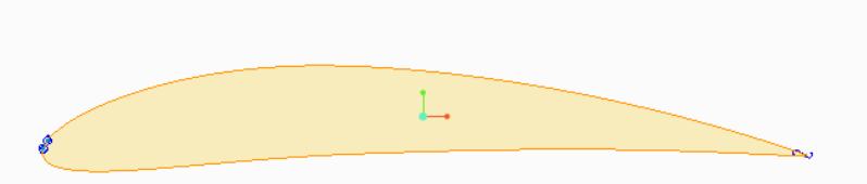
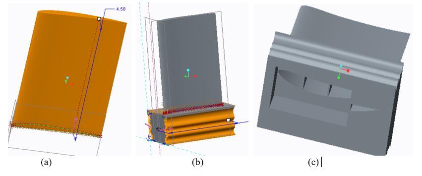
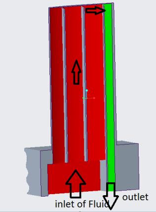
Fig 8:Importedmodel Fig 9: Meshedmodel
Fig 12: VelocityVector
International Research Journal of Engineering and Technology (IRJET) e ISSN: 2395 0056 Volume: 08 Issue: 12 | Dec 2021 www.irjet.net p ISSN: 2395 0072 © 2021, IRJET | Impact Factor value: 7.529 | ISO 9001:2008 Certified Journal | Page1195 ofthebladeand 653°Kfor coolingfluid.The Material properties (Titanium, Nickel alloy, Inconel 625) are takenconsiderforthecurrentstudy.Fig8,Represents the imported model from the igs format. The part is meshedwithtetrawithfineandobtainedthat102351 nodesand168523elements.
Fig 10:PressureContour
Fig 11:Temperature From above figure10, it is stated that, maximum pressure is1.245e+8Paobtainedatentryofthefluid.whileleaving, with effect of cooling and surface friction the pressure is reduced to 3.972e+6 Pa From above figure 11, it is represented the temperature. The low temperature of the fluid is entering into the turbine blade and it takes maximum temperature at entry level and leaves the with lesstemperatureis567K
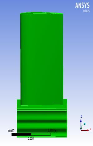
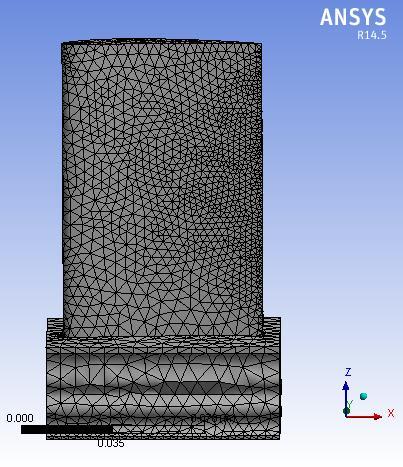
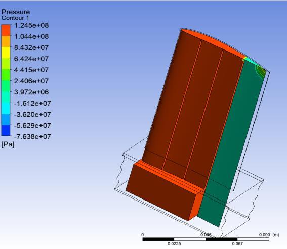
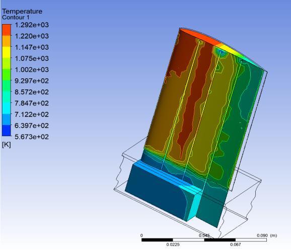
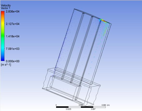
Fig 14: Deformation
Fig 15: Stress
ThepressureatdifferentReynoldsnumbers fromtheCFD simulation is noted and imported to the same model to estimate the deformation, stress, strain and frequency of thegasturbinebladebyusingFSITechnique.
Fig 16: Strain
Fig 13:VelocityStreamline
The velocity (fig 12), vector is represented based on the Reynolds number. From above figure 2.836e+4 m/sec velocity of the fluid is identified. The velocity streamline (Fig 13), is represented based on the Reynolds number. From above figure 2.836e+4 m/sec velocity of the fluid is identified. Static Structural and Modal Analysis
International Research Journal of Engineering and Technology (IRJET) e ISSN: 2395 0056 Volume: 08 Issue: 12 | Dec 2021 www.irjet.net p ISSN: 2395 0072 © 2021, IRJET | Impact Factor value: 7.529 | ISO 9001:2008 Certified Journal | Page1196
From above figure14, it was observed that deformation is occurred at the cooling sections due to lack of material. The maximum deformation 0.017319mm is obtained at first passage section and minimum 0mm is at holding portion of the blade. From the figure 15, Maximum stresses are produced at the internal passage of the blade because of weak material zone. The maximum stress is 3.91MPaatfluidpassageandminimumis1.679e 7MPaat holdingportionoftheblade.
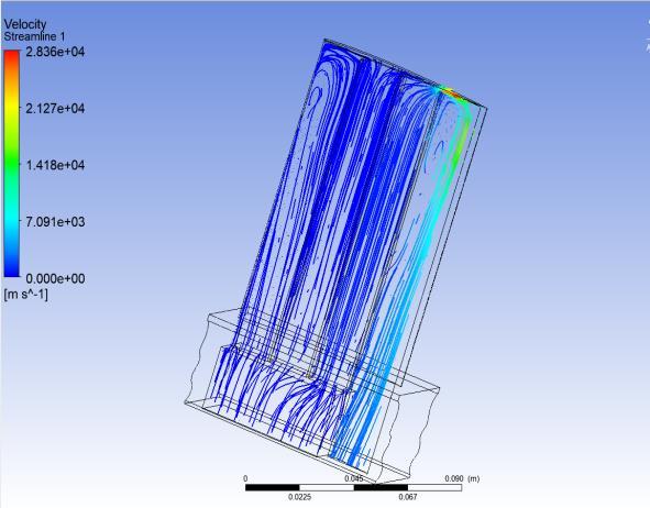
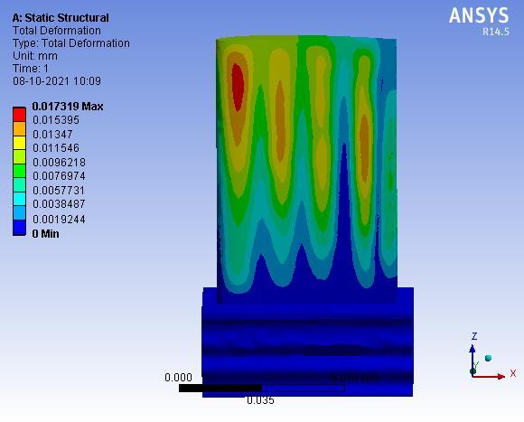
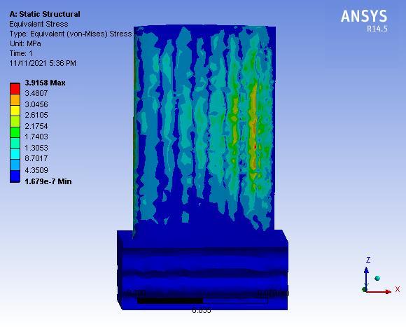
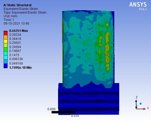
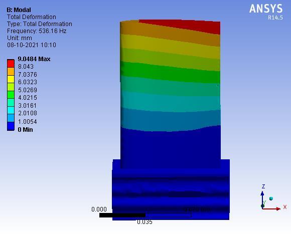
Fig 17: Mode1
Fromthe figure 16, Stainis definedaschange in length to original length. The maximum strain is 0.44251 obtained at the exit path of the fluid and minimum at holding portionoftheblade.Fromthefigure17,Inmodalanalysis, at different mode shapes different deformation and frequencies will obtain. In mode 1, the frequency is 536.16Hz with maximum deformation is 9.0484mm and minimumis0mm
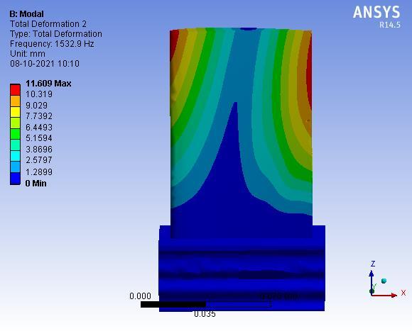
Fig 18: Mode2
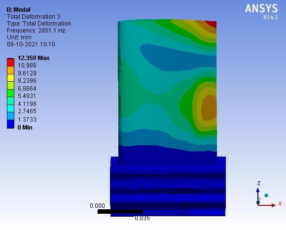
Fig 19: Mode3 In mode 2 (fig 18), the frequency is 1532.9Hz with maximum deformation is 11.609mm and minimum is 0mm. In mode 3 (Fig 19), the frequency is 2851.1Hz with maximumdeformationis12.359mmandminimumis0mm
International Research Journal of Engineering and Technology (IRJET) e ISSN: 2395 0056 Volume: 08 Issue: 12 | Dec 2021 www.irjet.net p ISSN: 2395 0072 © 2021, IRJET | Impact Factor value: 7.529 | ISO 9001:2008 Certified Journal | Page1197
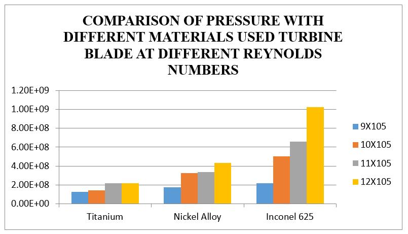
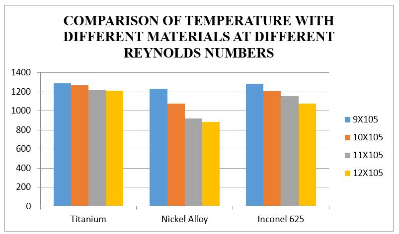
Result and discussions Graph Comparisonof(a)Pressureand(b)Temperature withdifferentmaterialsatdifferentReynoldsnumbers.
International Research Journal of Engineering and Technology (IRJET) e ISSN: 2395 0056 Volume: 08 Issue: 12 | Dec 2021 www.irjet.net p ISSN: 2395 0072 © 2021, IRJET | Impact Factor value: 7.529 | ISO 9001:2008 Certified Journal | Page1198
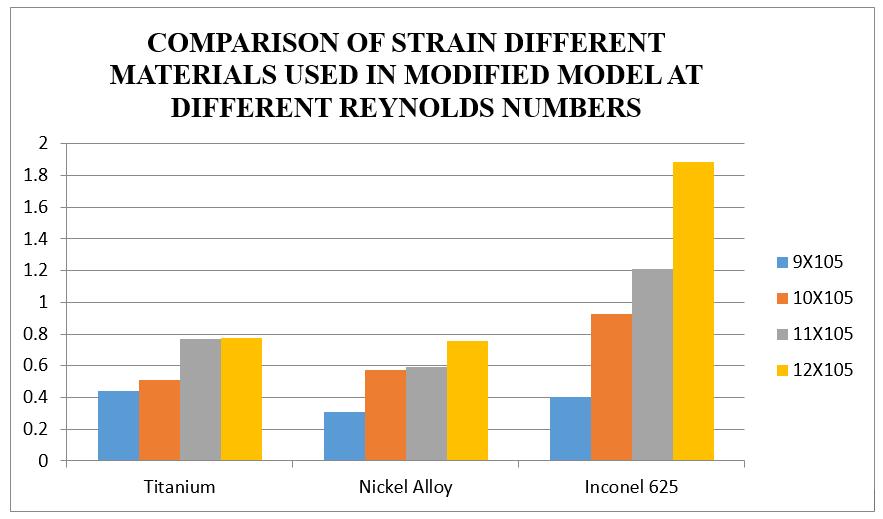
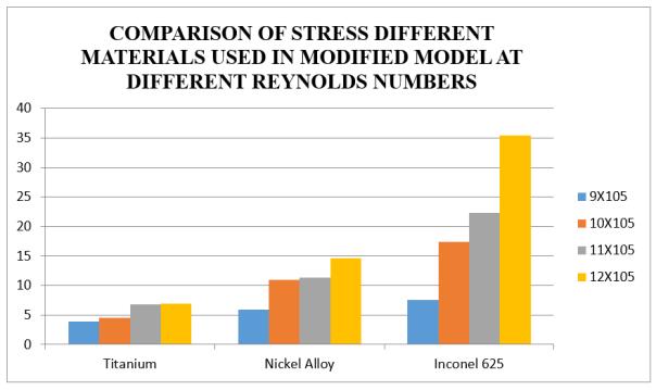
From the above graph(e), it is observed that the strain value is increasing for 12X105 Reynolds number for Inconel 625 and Decreasing at all Reynolds number for Titanium material of blade. From the above graph(f), it is observed that the stress value is increasing for 12X105 Reynolds number for Inconel 625 and Decreasing at all ReynoldsnumberforTitaniummaterialofblade.
Graph comparisonof(e)strainand(f)stressfordifferent materialsusedinturbinebladeatdifferentReynolds numbers
From the above graph(a), it is observed that the Pressure valueisincreasedfor12X105 ReynoldsnumberforInconel 625 material and Decreasing for titanium because of its mechanical properties. From the above graph(b), it is observed that the Temperature value is increasing at 12X105 Reynolds number for titanium material and decreasing at 9X10⁵ Reynolds number for nickel alloy material.
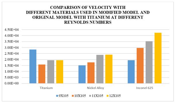
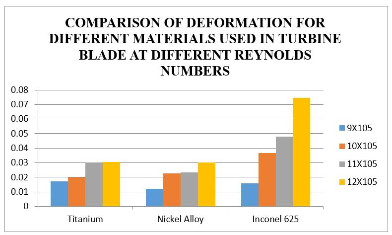
Graph Comparisonof(c)Velocity(d)deformationwith differentmaterialsusedinturbinebladeatdifferent Reynoldsnumbers. From the above graph(c), it is observed that the Velocity valueisincreasingat12X105 and9X105 Reynoldsnumber forInconel625,Titaniummaterials.Fromtheabovegraph (d), it is observed that the deformation (mm) value is increasing from 9 to 12X105 Reynolds number for Inconel 625 and Decreasing at all Reynolds number for Titanium materialofblade.
[3] Cun liang Liu, Hui ren Zhu, Jiang tao Bai, Du chun Xu, “Filmcoolingperformanceofconvergingslot holerowson agasturbineblade,InternationalJournalofHeatandMass Transfer,Volume53,Issues23 24,November2010,Pages 5232 5241.
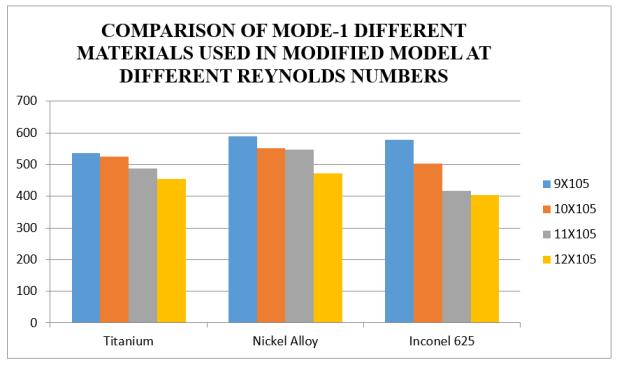
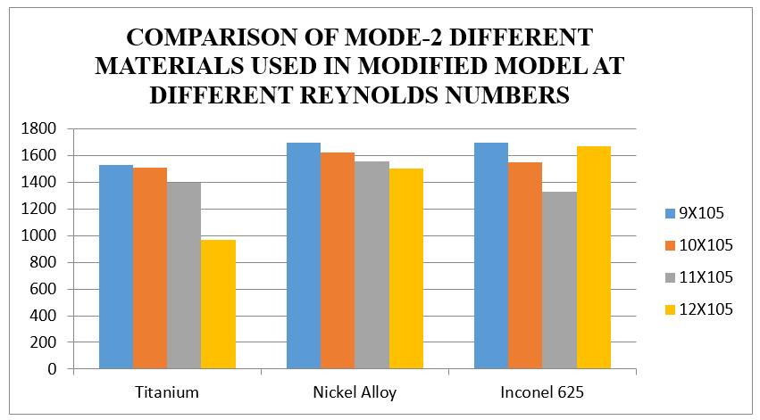
Fromtheabovegraph(g),itisobservedthatthemode1is increasingfor9X105 ReynoldsnumberforInconel625and Decreasing at all Reynolds number 12X105 for Inconel materialofblade.Fromtheabovegraph(h),itisobserved that the mode 2 is increasing for 9X10⁵ Reynolds number for Inconel 625 and Decreasing at all Reynolds number 12X105 fortitaniummaterialofblade.
[4]J.P.E.Cleeton,R.M.Kavanagh,G.T.Parks,“Bladecooling optimisation in humid air and steam injected gas turbines”, Applied Thermal Engineering, Volume 29, Issue 16,November2009,Pages3274 3283.
[5]JuryPolezhaev, “Thetranspirationcoolingforbladesof high temperatures gas turbine”, Energy Conversion and Management, Volume 38, Issues 10 13, July September 1997,Pages1123 1133.
[6] D. Lakehal, G. S. Theodoridis, W. Rodi, “Three dimensional flow and heat transfer calculations of film coolingattheleadingedge ofa symmetrical turbine blade model”, International Journal of Heat and Fluid Flow, Volume22,Issue2,April2001,Pages113 122.
CONCLUSION In this work a turbine blade is designed and modelled in Creo 2.0 software. The materials of turbine blade are Titanium, Nickel and Inconel 625. CFD analysis is done to determinethepressuredistribution,velocity,temperature distribution, deformation, strain, stress and frequency by applying the Reynolds numbers 9x105,10x105,11x105 and 12x105 Fromthesimulation,thefollowingresultsarepredicted.
International Research Journal of Engineering and Technology (IRJET) e ISSN: 2395 0056 Volume: 08 Issue: 12 | Dec 2021 www.irjet.net p ISSN: 2395 0072 © 2021, IRJET | Impact Factor value: 7.529 | ISO 9001:2008 Certified Journal | Page1199
The Pressure, velocity and temperature value is increasing at 12X105 Reynolds number for Inconel 625 material and reduced for titanium material.
[7]MahfoudKadja,GeorgeBergeles,“Computationalstudy ofturbinebladecoolingbyslot injectionofagas”,Applied Thermal Engineering, Volume 17, Issue 12, December 1997,Pages1141 1149.
Overall results of static and vibrational analysis, the Deformation, stress, strain and vibrations are less for Titanium material while compared with othermaterials REFERENCES [1] Jaeyong Ahn, M.T. Schobeiri, Je Chin Han, Hee Koo Moon “Effect of rotation on leading edge region film cooling of a gas turbine blade with three rows of film cooling holes” International Journal of Heat and Mass Transfer, Volume 50, Issues 1 2, January 2007, Pages 15 [2]25. Zhihong Gao, Diganta P. Narzary, Je Chin Han, “Film coolingonagasturbinebladepressuresideorsuctionside withaxial shapedholes”International Journal of Heat and Mass Transfer, Volume 51, Issues 9 10, May 2008, Pages 2139 2152
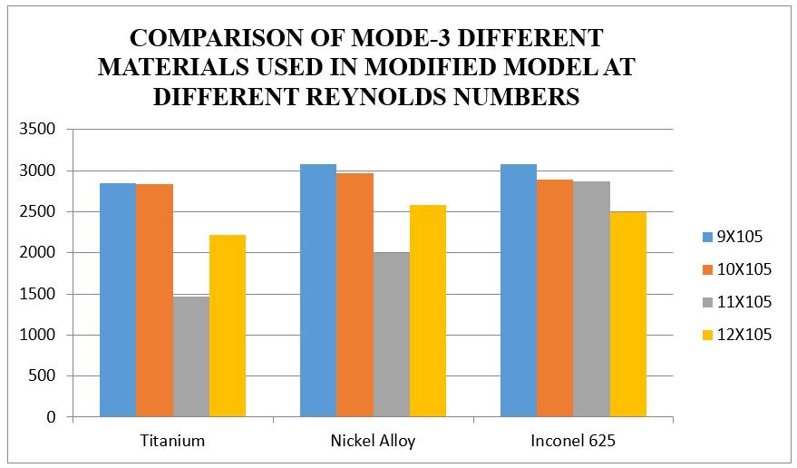
From the above graph it is observed that the mode 3 is increasingfor9X105 ReynoldsnumberforInconel625and Decreasing at all Reynolds number 12X105 for titanium materialofblade.
Graph comparisonofmode 1(g)andmode 2(h) frequencyfordifferentmaterialsusedinturbinebladeat differentReynoldsnumbers
Graph i: comparisonofmode 3frequencyfordifferent materialsusedinturbinebladeatdifferentReynolds numbers
International Research Journal of Engineering and Technology (IRJET) e ISSN: 2395 0056 Volume: 08 Issue: 12 | Dec 2021 www.irjet.net p ISSN: 2395 0072 © 2021, IRJET | Impact Factor value: 7.529 | ISO 9001:2008 Certified Journal | Page1200 [8] Bruno Facchini, Giovanni Ferrara, Luca Innocenti, “Blade cooling improvement for heavy duty gas turbine: theaircoolanttemperaturereductionandtheintroduction of steam and mixed steam/air cooling”, International Journal of Thermal Sciences, Volume 39, Issue 1, January 2000,Pages74 84. [9] Yiping Lu, David Allison, Srinath V. Ekkad, “Turbine Bladeshowerheadfilmcooling:Influenceofholeangleand shaping” International Journal of Heat and Fluid Flow, Volume28,Issue5,October2007,Pages922 931. [10]J.P.E.Cleeton,R.M.Kavangh,G.T.Parks,“BladeCooling Optimisation in Humid air and Steam Injected Gas Turbines”,AppliedThermalEngineering29(2009)3274 3283.