2 minute read
SteamTurbine


Volume: 08 Issue: 12 | Dec 2021 www.irjet.net p-ISSN: 2395-0072
DESIGN, CFD AND VIBRATIONAL ANALYSIS OF GAS TURBINE BLADE WITH COOLING
Advertisement
Archana Pulicherla1 , Mr. Ganta Suresh2 , Dr. Naveen Kilari3
1stM.Tech Student, Department of Mechanical Engineering, Vemu Institute of Technology, P.Kothakota Chittoor, A.P. 2ndAssociate Professor, Department of Mechanical Engineering, Vemu Institute of Technology, P.Kothakota Chittoor, A.P. 3rdProfessor, Department of Mechanical Engineering, Vemu Institute of Technology, P.Kothakota, Chittoor, A.P. -----------------------------------------------------------------------*** ----------------------------------------------------------------------Abstract: Gas turbines are generally utilized in power age, aviation, and modern applications. By giving inside Cooling in the gas turbine edge, in this way, the hotness move rate improves. The cooling air is passed into the rib-upgraded serpentine sections into the sharp edges to accomplish entomb cooling. To achieve maximum efficiency, the internal Cooling path to be optimized so currently existing design of the gas turbine blade is replaced with the new design. In this thesis a turbine blade (with cooling) is modeled and drafted in Creo 2.0 software. The materials used for the Gas turbine blade are Titanium, Nickel and Inconel 625. The CFD Simulation is done and output parameters are pressure distribution, velocity and temperature distribution for the Reynolds numbers 9x10⁵, 10x105, 11x105 and 12x105. The pressure is imported to static structural to estimate the deformation, strain, stress distribution and frequencies of the gas turbine blade. 2. SteamTurbine 3. Shrouded Turbine 4. Shrouded-LessTurbine
1.2 THEORY OF OPERATION
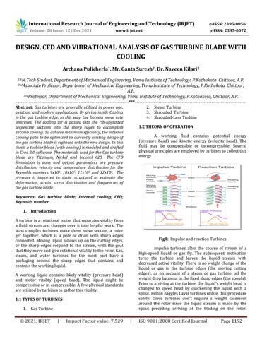
A working fluid contains potential energy (pressure head) and kinetic energy (velocity head). The fluid may be compressible or incompressible. Several physical principles are employed by turbines to collect this energy Fig1: Impulse and reaction Turbines impulse turbines alter the course of stream of a high-speed liquid or gas fly. The subsequent motivation turns the turbine and leaves the liquid stream with decreased active vitality. There is no weight change of the liquid or gas in the turbine edges (the moving cutting edges), as on account of a steam or gas turbine; all the weight drop happens in the fixed sharp edges (the spouts). Prior to arriving at the turbine, the liquid's weight head is changed to speed head by quickening the liquid with a spout. Pelton haggles Laval turbines utilize this procedure solely. Drive turbines don't require a weight casement around the rotor since the liquid stream is made by the spout preceding arriving at the blading on the rotor.
Keywords- Gas turbine blade; internal cooling; CFD; Reynolds number 1. Introduction
A turbine is a rotational motor that separates vitality from a fluid stream and changes over it into helpful work. The least complex turbines make them move section, a rotor get together, which is a pole or drum with sharp edges connected. Moving liquid follows up on the cutting edges, or the sharp edges respond to the stream, with the goal that they move and give rotational vitality to the rotor. Gas, steam, and water turbines for the most part have a packaging around the sharp edges that contains and controls the working liquid.
A working liquid contains likely vitality (pressure head) and motor vitality (speed head). The liquid might be compressible or in compressible. A few physical standards are utilized by turbines to gather this vitality.
1.1 TYPES OF TURBINES
1. Gas Turbine