International Research Journal of Engineering and Technology (IRJET)
e-ISSN: 2395-0056
Volume: 07 Issue: 04 | Apr 2020
p-ISSN: 2395-0072
www.irjet.net
A Review on Design and Analysis of Automatic oil filling pump Mr. Milan A. Chodavadiya1, Mr. Dhruv B. Fefar2, Mr. Bhavik K. Dholu3 1,2,3Students
of mechanical Engineering, Lukhdhirji Engineering College, Morbi-2, Gujarat 363642
---------------------------------------------------------------------***--------------------------------------------------------------------valve. Hose assemblies are generally preferred to rigid piping for connecting the power pack to actuators. The arrangement of interconnected components that hydraulic power packs consist of a reservoir tank that control hydraulic energy. In the manufacturing of tiles house the hydraulic fluid, which is the basic working industrious the die and punch has become the main medium. The reservoir is also equipped with an air component for the consideration of the design and breather at the top to maintain the pressure in the tank accuracy, small error in the die can cause huge damage at the atmospheric pressure and filters the oil to 40 in the accuracy as well as in design. In that scenario we microns. observe that the ceramic people use rubber cover on the die for smooth operation and ease in design but the 2. WORKING PRINCIPAL oil pressure between die and rubber cover should be uniform. But in practical case the oil pressure is not The working of a power pack commences when the uniform in the procedure. Another one problem is that pump is initialized with the help of an electric motor the oil filling operation by manual hand pump is very coupled to it. The oil is pumped from the reservoir laborious, moreover it’s very time consuming, and it along the suction line through a suction strainer with a required very high pressure and though the rubber capability to retain the foreign particles up to 149 cover is sometimes damage and the cost of the rubber microns. is very high for changing is at a time. So, the aim of this project is to design hydraulic system and analyzing different pumps for the application.
Abstract – Automatic oil filling pump is an
Key Words: Die and punch, design and accuracy, oil pressure, manual hand pump, laborious, high pressure, rubber cover. 1. INTRODUCTION Most of cases, industries have to face a many types of problem and it may be create big loss in company so that we can identified problem. A hydraulic system is any component that uses a fluid to generate and transmit energy from one point to another within the enclosed system. This force can be in the form of linear motion, force or rotary motion. Some industries can give a big chance to work on that problem and find optimum solution for that company and also system will work very quickly. In past, oil is filled by hand operated and it may be very time consuming process so that it can be replaced by automatic oil filling pump. It consists basically of an integral electrical motor, with associated tank. The pump or motor unit may be mounted on the tank or separately and packs are usually available in either horizontal/vertical configuration. Relief and check valves are normally incorporated on the tank. The basic unit may be piped to the cylinders or actuators through a suitable control
From the suction line the oil is forced in to the pressure line through the pump at 35 bars. There is provision to measure the pressure, with the help of a pressure gauge. An isolator is used to measure the pressure immediately in any line. When the set of pressure is reached, the fluid moves to the cylinder present at the fixture (clamp). The hydraulic energy of the fluid is converted back to the energizing of the solenoid valve, the linear movement of the clamps (clamping and unclamping) is controlled. When the solenoid valve is energized in reverse, unclamping of the work piece occurs. There is a return line provided so that the used fluid may be utilized again. Due to the friction losses,
Š 2020, IRJET
ISO 9001:2008 Certified Journal
|
Impact Factor value: 7.34
|
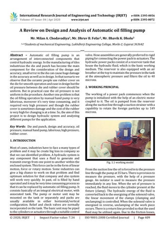
Fig. 1.1 working model
|
Page 409