Structural Analysis of Wind Turbine Blade

Page 1


International Research Journal of Engineering and Technology (IRJET) e-ISSN:2395-0056

Volume: 12 Issue: 05 | May 2025 www.irjet.net p-ISSN:2395-0072

Structural Analysis of Wind Turbine Blade

Dept. of Mechanical Engineering, G. H. Raisoni College of Engineering and Management, Maharashtra, India

Abstract - This study focuses on the structural analysis and design optimization of wind turbine blades to enhance efficiency, reliability, and cost-effectiveness. Wind turbine blades experience complex loads, including aerodynamic forces, gravitational effects, and extreme weather conditions.Ensuringtheirdurabilityandmaximizingenergy capture efficiency is crucial for sustainable wind energy systems. Finite element analysis (FEA) is employed to evaluate stress distribution, deflection, natural frequencies, and failure modes such as buckling, delamination, and fatigue. The study compares conventional glass-fiberreinforced composites with advanced carbon-fiber composites to determine optimal material choices for strength,weight,andcostbalance.

Optimization techniques, including genetic algorithms and gradient-based methods, refine blade design parameters such as length, airfoil shape, chord distribution, and twist angle. These approaches aim to minimize blade mass while maintaining structural integrity and performance. Material distribution is also optimized to enhance recyclability and sustainability. Manufacturing constraints and cost considerations are integrated into the design process, exploring innovations like hybrid materials and adaptive structures. The findings contribute to the development of next-generation wind turbine blades, supporting the expansionofefficientandsustainablewindenergysolutions.

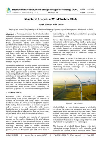
1.INTRODUCTION

Windmills, iconic structures of ingenuity and sustainability, have graced landscapes for centuries as symbols of innovation and utility. These remarkable machinesharnessthepowerof wind to perform essential tasks, making them a cornerstone of human development and a testament to our relationship with nature. Originating over a thousand years ago, windmills were initiallydesignedtogrindgrainintoflourandpumpwater, playingavitalroleinagricultureandearlyindustry.

At their core, windmills are marvels of mechanical engineering. Their sails or blades catch the wind's kinetic energy, converting it into rotational motion to power machinery.Thissimpleyeteffectiveprincipleunderscores humanity's enduring quest to harness renewable resources. Over time, windmills evolved in design and purpose, from the traditional post and tower mills of

medievalEuropetothesleek,modernturbinesgenerating cleanelectricitytoday.

Beyond their functional significance, windmills carry cultural and aesthetic value. They stand as picturesque landmarks in rural landscapes, often evoking a sense of nostalgia and harmony with the environment. In an era increasingly focused on sustainability, windmills and their contemporary counterparts, wind turbines underscore the importance of renewable energy in combatingclimatechange.

Whether viewed as historical artifacts, practical tools, or symbols of a greener future, windmills inspire awe and remind us of humanity’s ability to innovate in harmony with nature. Their story is a journey through time, intertwining tradition, technology, and an enduring relianceonthepowerofthewind.

1.1–Windmills

Windmill blades are the defining feature of windmills, embodying the essence of harnessing wind energy and transformingitintomechanicalorelectrical power.These dynamic components, designed to capture the kinetic energy of the wind, are vital to the functionality and efficiencyofwindmills,bothtraditionalandmodern.Their evolutionreflectscenturies ofengineeringinnovationand adaptationtochangingneedsandtechnologies.

The journey of windmill blades begins with their rudimentary wooden designs in early windmills, used primarily for grinding grain or pumping water. These

Figure

International Research Journal of Engineering and Technology (IRJET) e-ISSN:2395-0056

Volume: 12 Issue: 05 | May 2025 www.irjet.net p-ISSN:2395-0072

early blades were simple yet effective, leveraging basic aerodynamic principles to rotate and drive machinery. Over time, advancements in materials and understanding of wind dynamics revolutionized their design. Today, modernwindturbinesareequippedwithsleek,precisionengineered blades made of advanced composites like fiberglass and carbon fiber, designed to maximize energy capture while withstanding harsh environmental conditions.

Aerodynamic optimization plays a critical role in blade design, ensuring that they can generate power efficiently at varying wind speeds. From a cultural perspective, windmill blades are iconic, seen spinning atop historic millsintheEuropeancountrysideortoweringturbineson modern wind farms. Their visual presence often symbolizes humanity's ingenuity and commitment to sustainableenergy.

As the demand for renewable energy grows, windmill blades stand at the forefront of innovation, enabling cleaner,greenersolutionstopowertheworld.Theyserve as both a bridge to the past and a beacon of progress, showcasing the harmonious integration of nature and technology.

The size and number of blades vary depending on the windmill's purpose. For electricity generation, modern turbines often feature three blades for optimal balance, efficiency, and reduced noise. These blades are not only technological marvels but also represent the synergy betweenengineeringandrenewableenergyinnovation.

Thedesignofwindmillbladesisacornerstoneofmodern wind energy systems, directly influencing their efficiency, performance, and environmental impact. As the primary componentresponsibleforcapturingthekineticenergyof the wind, these blades are marvels of engineering, combining advanced materials and aerodynamic principlestooptimizeenergyconversion.

A well-designed windmill blade maximizes energy capture by utilizing an airfoil shape, precision angles, and lightweight materials. The challenge lies in balancing strength, durability, and cost while ensuring the blades canendureharshweatherconditionsandfluctuatingwind loads over their lifespan. Modern innovations, such as smart materials and recyclable designs, have further advancedbladetechnology,makingitintegraltotheglobal pushforrenewableenergy.

Understanding the complexities of windmill blade design offers insight into the interplay between engineering ingenuity and environmental stewardship, driving the evolutionofsustainableenergysolutions.

Theoptimizationofwindmillbladedesignisessentialfor enhancing the efficiency, reliability, and sustainability of wind energy systems. As wind energy continues to play a criticalroleintransitioningtorenewableenergy,thereisa growing need to maximize the performance of windmills whileminimizingcostsandenvironmentalimpacts.

2. Literature Review

Maalawi and Badr [1] examined the mechanical interaction between turbine blades and the electric generator, focusing on strategies for controlling pitch and rotational speed. Their study highlights the complexity of this problem, which involves numerous factors, relationships, and constraints. Designing optimal blades requires addressing aerodynamic, structural, and control challenges. Nevertheless, the design process can be effectively handled through an iterative and step-by-step approach. In aerodynamic optimization, the blade is modeled as a series of cross-sections along the pitch axis, with each section characterized by its aerofoil profile, chord length, and attachment angle, influenced by both collective and local twist angles. Thresher and Dodge [2] exploredhowtheblade’spitchangleisdeterminedbythe broader control strategy of the wind energy system. Accurately computing the airflow around rotating blades remains a highly complex task. Solving the threedimensional Navier-Stokes equations within a rotating frame provides detailed insights into the wind flow and the forces exerted on the turbine surfaces, but the associated computational costs make this approach impractical for typical design and analysis work. Tangler [3] explained that the Blade Element Momentum (BEM) theory offers a simplified, one-dimensional approach to modeling blade aerodynamics. Despite its simplifications, it is widely used in the wind energy industry because it can predict blade performance with reasonable accuracy. United Technologies Corporation [4] conducted a comprehensive experimental modal analysis, employing a hydraulic shaker and multiple accelerometers to measure

Figure1.2-WindmillBlade

International Research Journal of Engineering and Technology (IRJET) e-ISSN:2395-0056

Volume: 12 Issue: 05 | May 2025 www.irjet.net p-ISSN:2395-0072

one edgewise and two flapwise accelerations at approximately 20 blade stations. The resulting frequency response functions were compared to outcomes from a three-dimensional shell element finite element (FE) model. Their study focused on analyzing the dynamic characteristics associated with the seven lowest natural frequencies. Larsen and Kretz [5] utilized modal analysis techniquesto identifydominant modeshapesinmediumsized wind turbine blades. Their approach successfully captured the primary modes related to the three lowest natural frequencies by analyzing the transfer function between a sinusoidal force applied at the blade tip and accelerometer responses recorded across up to 68 blade stations.

Larsen, Hansen, Baumgart, and Carlén [6] evaluated the dynamic behavior of wind turbine blades, including natural frequencies, damping ratios, and mode shapes, through modal analysis methods. Their work, conducted on the LM 19m blade, provides insights applicable to various blade designs. They assessed measurement reliability using standard deviations and coefficients of variation, notinghighaccuracyin natural frequenciesand damping but greater variability in mode shape assessments.Primarydeflectionmodesexhibitedminimal uncertainty, whereas secondary, particularly torsional, deflections showed higher error margins. Although systematic errors such as blade support flexibility and sensor arrangement were acknowledged, they were not quantified. Dimitriadis [7] assessed the performance of Horizontal Axis Wind Turbines (HAWTs) using two analytical methods: Computational Fluid Dynamics (CFD) and Blade Element Momentum Theory (BEMT). He comparedtheresultsfrombothmethods,conductingboth two-dimensional and three-dimensional analysestostudy the flow fields around turbine blades. Drag and lift coefficientswereevaluatedagainstavailableexperimental data, revealing the superior accuracy and advantages of CFD modeling compared to BEMT. Dhurpate, Sutar, and Kale [8] analyzed the performance of a small horizontalaxis wind turbine rotor blade using various airfoil types. The study assumed low wind speeds and low Reynolds numbers,usinga singleairfoiltypeacross thebladespan. The rotor, with a 2-meter diameter and three blades, was modeledusingfourdifferentairfoils,withatipspeedratio of 7. Among all tested airfoils, the E387 airfoil demonstratedthebestperformance.SolandandThuné[9] studied the rotor blade performance of a wind turbine with a diameter of 165 meters. They used computational tools such as XFLR5 and QBlade for simulations, applying the Blade Element Momentum Theory for analysis. Their findings detailed rotor performance under various operationalloadsandindicatedthattheNACA63-6XXand NACA 64-6XX airfoils offered the best performance improvements compared to other tested airfoils. Kale,

Birajdar, and Sapali [10] designed new airfoil shapes to enhance wind turbine performance, creating distinct airfoilsfortherootandtipsections.TheyemployedBlade Element Momentum Theory in designing a small wind turbine blade and conducted numerical analysis using QBladesoftware. Their resultswere compared withthose fortheNACA2412andSG6042airfoils,furthercomparing the performance of blades constructed with different individual airfoils using the same software. Mahri and Rouabah[11]conducteda dynamicstress evaluationon a wind turbine blade, which was designed using blade element theory. Their analysis incorporated beam theory for dynamic behavior and utilized both finite element modeling and blade motion equations to perform modal analysis. Edon [12] designed a 38-meter blade for a 1.5 MW wind turbine using the blade element momentum (BEM)theory.Inhisproposedfuturework,heintroduced achorddistributionformula,whichhasbeenimplemented in this study. Giguere and Selig [13] presented a methodology for optimizing blade geometry in wind turbine rotor design. Their approach utilized preprogrammed software tools to enhance both structural and cost-efficiency models. Jureczko, Pawlak, and Mezyk [14] applied BEM theory in blade design and used ANSYS softwaretocalculatetheblades’naturalfrequencies.Mode shapes were determined using a Timoshenko twisted, tapered beam element formulation. A genetic algorithm was employed to optimize the blade’s performance by reducingvibrations,loweringcosts,increasingoutput,and improving stability. Guo, Wu, Xu, and Li [15] developed a 1.5 MW wind turbine rotor with a 35-meter blade length using MATLAB. Their results confirmed the viability of MATLAB for large-scale turbine design, highlighting its cost-effectivenessinearly-stageaerodynamicanalysisand performance optimization. Computational fluid dynamics (CFD) results were used for validation. Carcangiu [16] utilizedtheFLUENTCFDtooltogaindetailedinsightsinto fluidflowbehavioroverwindturbineblades,contributing to more precise aerodynamic assessments. Jackson et al. [17] carried out a preliminary study for designing a 50meter-long wind turbine blade using both fiberglass and carbon fiber composite materials. Adjustments in crosssectional thickness were made to improve structural performance, and aerodynamic analyses were conducted forbothcleanandcontaminatedsurfaceconditions.Wang et al. [18] investigated turbines of three different sizes to developacost-optimizationmodel thatmaximizedannual energy output. By using an enhanced BEM model integrated with blade structural dynamics, they successfully demonstrated reduced energy production costs.

Karam and Hani [19] implemented a multi-dimensional optimization technique to maximize the blade’s natural frequency. The optimization process considered

International Research Journal of Engineering and Technology (IRJET) e-ISSN:2395-0056

Volume: 12 Issue: 05 | May 2025 www.irjet.net p-ISSN:2395-0072

parameters such as cross-sectional area, radius of gyration,andchordlength,andtheapproachprovedtobe computationallyefficient.Hsu[20]developedatheoretical frameworkforanalyzingtwisted,taperedbeamsusingthe spline collocation method. The provided expressions for cross-sectional area and moment of inertia are used as a basis in this work. Rao and Gupta [21] analyzed twisted, tapered, rotating Timoshenko beams using the finite element method. They derived the stiffness and mass matrices through shape functions and determined the natural frequencies by reformulating the problem into an eigenvalue analysis. Hillemer et al. [22] designed wind turbines with power outputs exceeding 5 MW by scaling existing rotor models. Using simple beam theory, they assessed stresses, bending moments, and natural frequencies. To reduce blade weight, airfoil shell thicknesses, as well as web and flange dimensions, were adjusted across sections,constrained by requirements for structural strength and minimal mass. Gooden [23] studied the two-dimensional aerodynamic properties of theFX66S196V1airfoil,whichisusedinthisreport.The investigation focused on lift and drag coefficients over various Reynolds numbers. Bharath [24] designed a 45meterbladeforawindspeedof12 m/susingBEMtheory, calculating flow angles, thrust, torque, and power. The blade was modeled as a hollow tapered beam, with stiffness and mass matrices derived from the crosssectional area and moment of inertia. Chord length dictatedthetaper,andairfoilthicknessdefinedtheheight. Natural frequencies were evaluated in both axial and transverse directions. Optimization using MATLAB’s fmincon function focused on maximizing power and minimizing mass under different constraint scenarios, yielding optimized chord profiles and performance visualizations. Miller et al. [25] provided an overview of recent advances in simulation techniques, tools, and applications for wind energy. The industry increasingly depends on CFD to design innovative turbines, though BEMremainsmoreprevalentinearlydesignphasesdueto itssimplicity.Theyemphasizedtheneedfornewtoolsthat integrate CFD earlier in the process and highlighted the roleofalgorithmicoptimization inminimizingreliance on trial-and-errormethods.

Madsen et al. [26] and parallel studies using bladeresolved rotor models often excluded hub geometry, yet CFD techniques successfully captured spanwise and tip flow patterns. These flow features significantly influence aerodynamic loads both within and outside the rotor plane. Horcas et al. [27] found that tools like HAWC2, based on OpenFAST physicsmodels,tendtooverestimate loads on 10 MW turbines at sub-rated wind speeds. Moreover, these tools often underestimate the performance benefits of curved blade tips. Due to their reliance on fixed drag polars and limitations in gradient

calculations, their effectiveness for optimization is reduced, especially when refining airfoil shapes. Batay et al.[28]demonstratedthataerostructuraloptimizationcan enhance wind turbine blade performance by reducing blademass,whichcontributestohigherenergyoutputand cost savings. They recommended future work focus on improvingoptimizationtechniquesandexpandingthemto a wider range of turbine types. Jureczko, Pawlak, and Mezyk [29] created a general-purpose numerical model for wind turbine blade optimization and developed a software tool for multi-objective discrete-continuous optimization.UsingANSYSparametricmodeling,userscan vary blade thickness and key dimensions. The tool incorporates a modified genetic algorithm to optimize performance basedonmultipleobjectivesunderspecified constraints. Chattot [30] argued that while an optimal rotor does not strictly meet the Betz limit at each blade section,itdoessatisfytheconditiononaverageacrossthe Trefftz plane. The optimization problem remains wellposedininviscidflowaslongastheairfoil’smaximumlift coefficient is respected. The study concluded that viscous effects have minor influence on the ideal blade shape, mainly reducing overall efficiency. The method is adaptabletogeometricconstraints,suchasoptimizingfor a given chord distribution. Fuglsang and Madsen [31] introduced a direct design method for horizontal-axis wind turbines, employing numerical optimization and various computational models. These included aerodynamic, structural, aeroelastic (time-domain), extreme load, and noise prediction analyses. They also estimated manufacturing costs based on design loads. Jureczko, Pawlak, and Mezyk [32] (in a follow-up study) again emphasized their optimization software, capable of creating diverse blade models through ANSYS scripting. The tool applies a modified genetic algorithm for optimizing blades against several criteria under various constraints.

Schubel and Crossley [33] noted that the three-blade horizontal-axis configuration dominates today’s wind turbine market due to its efficiency, control, and scalability. Supported by a global supply network, this design continues to outperform alternatives. Blade geometriesarecarefullyshapedtoenhanceaerodynamics, withincreasingwidth,twist,andthicknessnearthehubto withstand higher bending moments. While current innovations focus on scaling turbine size, future advancements may prioritize performance enhancements via new materials and airfoil designs, especially as physicalgrowthreachespracticallimits.

3. Design of the blade

Themodel as provided by Eleation has the dimensions as shown in ‘Figure 3.1’. It is made from aluminum alloy, it

International Research Journal of Engineering and Technology (IRJET) e-ISSN:2395-0056

Volume: 12 Issue: 05 | May 2025 www.irjet.net p-ISSN:2395-0072

providesalightweightyetdurablestructurewithexcellent corrosion resistance.This windmill blade is designed for small-scale wind energy applications. The total length of thebladeis9500mm.

3.1-BladeDimensions

The ‘Figure 3.2’ shows the aerofoil geometry of the windmill blade. The total width of the blade is 1010mm whereas the maximum thickness is 214mm. This blades hasagradualtwistfromroottotip.

4. Methodology

Methodologyofthisprojectconsistsoffollowingpointsas guidedbytheEleationteam.

i.Initial Blade Geometry:

● Aerofoil shape to be used for the blade's initial shape.

ii.Material Selection:

● Aluminiumalloys.

iii.Mesh Selection:

● Hexagonalmesh

● Meshsize-45mm

‘Figure 4.1’ below shows the meshed wind turbine blade, hereprimaryhexagonal meshofsize45mmisused.There are 26958 nodes and 109511 elements in the meshed wind turbine blade. There are tria elementsonly where it isnecessary;allothersaretetraelements.

4.1. Transient Structural Analysis:

Transient Structural Analysis is a finite element analysis techniqueusedtoevaluateastructure’sresponsetotimedependent loads, displacements, or environmental conditions. It accounts for inertia and damping effects, making it essential for studying impact, vibrations, and shock loads. It employs explicit methods for shortduration,high-speedeventsandimplicitmethodsforlongduration, gradual changes. Applications include earthquake-resistant buildings and shock-wave effects on structures. By incorporating time-dependent boundary conditions, transient analysis ensures more accurate and realisticstructuralperformancepredictions.

● MaxPressure:101325Pa;

● Applypressureonthebladeandconstraintthe endlocationsi.e,holes

● Performtheanalysisfor100sec.

‘Figure4.2’showsthatthepressureof101325Pa,whichis atmospheric pressure is applied on the face of the wind turbinebladeandtheboltingholeshavebeenfixedforthe transient structural analysis of the blade.The analysis is performed for 100 sec, and the results are as shown below.

Figure
Figure3.2-BladeAerofoilShape
Figure4.1-MeshedBlade
Figure4.2-TransientStructuralAnalysisloadingonBlade

International Research Journal of Engineering and Technology (IRJET) e-ISSN:2395-0056

Volume: 12 Issue: 05 | May 2025 www.irjet.net p-ISSN:2395-0072

Output:

● Stress

‘Figure 4.3’ shows that the minimum stress developed duringthetransientstructuralanalysisis0.076301MPa,it occurs at the tip of the wind turbine blade. Whereas maximum stress developed during the transient stress analysisis649.12MPa,itoccursattheneckoftheblade.

Figure4.3-Von-MisesStress-649.12MPa

● Deformation

‘Figure 4.4’ shows that the minimum deformation during the transient structural analysis is 0mm, it occurs at the bolting holes of the wind turbine blade. Whereas maximumdeformationduringthetransientstressanalysis is1894.4mm,itoccursatthetipoftheblade.

Figure4.4-Deformation-1894.4mm

● Strain

‘Figure 4.4’ shows that the minimum strain during the transientstructuralanalysisis1.1877X10^-6,itoccursat the tip of the wind turbine blade. Whereas maximum strain during the transient stress analysis is 0.009193, it occursattheneckoftheblade.

‘Figure 4.4’ shows that the minimum factor of safety during the transient structural analysis is 0.43135, it occurs at the neck of the wind turbine blade. Whereas maximum factor of safety during the transient stress analysisis15,itoccursattheboltingholesoftheblade.

4.2. Static Structural Analysis:

Static Structural Analysis determines a structure’s responsetoconstantorslowlyvaryingloads,assumingno inertia or damping effects. It ensures equilibrium by analyzingstresses,strains,anddeformationsunderforces, pressure, thermal effects, and constraints. Used in civil, automotive, aerospace, and mechanical engineering, it evaluates load-bearing capacity, material strength, and failure risks. There are linear (small deformations, proportional behavior) and nonlinear (plasticity, large deformations, contact interactions) approaches. This analysisisessentialfordesigningsafe,efficientstructures like buildings, bridges, and machinery, ensuring they withstandappliedforceswithoutexcessivedeformation.

● MaxPressure:101325Pa;

● Applypressureonthebladeandconstraintthe endlocationsi.e.,holes

‘Figure4.7’showsthatthepressureof101325Pa,whichis atmospheric pressure, is applied on the face of the wind turbinebladeandtheboltingholeshavebeenfixedforthe

Figure4.5-Strain-0.009193
● FOS
Figure4.6-FOS-0.43135

International Research Journal of Engineering and Technology (IRJET) e-ISSN:2395-0056

Volume: 12 Issue: 05 | May 2025 www.irjet.net p-ISSN:2395-0072

static structural analysis of the blade.The results of the analysisareasshownbelow.

Figure4.7-StaticStructuralAnalysisloadingonBlade

Output:

● Stress

‘Figure 4.8’ shows that the minimum stress developed during the static structural analysis is 0.076551 MPa, it occurs at the tip of the wind turbine blade. Whereas maximum stress developed during the transient stress analysisis652.35MPa,itoccursattheneckoftheblade.

Figure4.8-Von-MisesStress-652.35MPa

● Deformation

‘Figure 4.9’ shows that the minimum deformation during the static structural analysis is 0mm, it occurs at the bolting holes of the wind turbine blade. Whereas maximumdeformationduringthetransientstressanalysis is1904.1mm,itoccursatthetipoftheblade.

Figure4.9-Deformation-1904.1mm

● Strain

‘Figure 4.10’ shows that the minimum strain during the staticstructuralanalysisis1.1908X10^-6,itoccursatthe tip of the wind turbine blade. Whereas maximum strain duringthetransientstressanalysisis0.0092361,itoccurs attheneckoftheblade.

● FOS

‘Figure 4.11’ shows that the minimum factor of safety duringthestaticstructuralanalysisis0.42922,itoccursat the neck of the wind turbine blade. Whereas maximum factorofsafetyduringthetransientstressanalysisis15,it occursattheboltingholesoftheblade.

4.3. Modal Analysis:

Modal Analysis determines a structure’s natural frequenciesandmodeshapes,essentialforunderstanding vibration characteristics. It helps prevent resonance, which can cause structural failure. This analysis assumes noexternal forces,focusing onhowthestructurevibrates duetoinherentpropertieslikestiffnessandmass.Usedin aerospace, automotive, civil, and mechanical engineering, itensuressafetyinbridges,engines,andmachinery.Modal analysis can be theoretical or numerical. It’s crucial for optimizing designs, reducing unwanted vibrations, and improving structural stability under dynamic conditions likeearthquakes,machineryoperation,orvehiclemotion.

● PerformModalAnalysiswithpre-stresscondition asStaticStructuralanalysis.

Figure4.10-Strain-0.0092361
Figure4.11-FOS-0.42922

International Research Journal of Engineering and Technology (IRJET) e-ISSN:2395-0056

Volume: 12 Issue: 05 | May 2025 www.irjet.net p-ISSN:2395-0072

● MaxFrequency:300Hz

‘Figure4.12’showsthatthemodalanalysisisdoneonthe windturbinebladeforthemaximumfrequencyof300Hz, keeping the static structural analysis performed on the bladeastheprestresscondition.Herewefindthefirstsix modes of natural frequency and their respective displacements.

4.12-ModalAnalysis

Output:

1. Mode1

‘Figure 4.13’ shows that the first mode of natural frequency occurs at 2.9614 Hz. Here minimum deformation is 0mm, it occurs at the bolting holes of the wind turbine blade. Whereas maximum deformation is 1.6483mm,itoccursatthetipoftheblade.

2. Mode2

‘Figure 4.14’ shows that the second mode of natural frequencyoccursat9.140Hz.Hereminimumdeformation is 0mm, it occurs at the bolting holes of the wind turbine blade. Whereas maximum deformation is 1.4954mm, it occursatthetipoftheblade.

4.14-

3. Mode3

‘Figure 4.15’ shows that the third mode of natural frequency occurs at 14.202 Hz. Here minimum deformation is 0mm, it occurs at the bolting holes of the wind turbine blade. Whereas maximum deformation is 2.751mm,itoccursatthetipoftheblade.

4.15-

4. Mode4

‘Figure 4.16’ shows that the fourth mode of natural frequency occurs at 31.533 Hz. Here minimum deformation is 0mm, it occurs at the bolting holes of the wind turbine blade. Whereas maximum deformation is 3.5472mm,itoccursatthetipoftheblade.

4.16-Mode4

5. Mode5

‘Figure 4.17’ shows that the fifth mode of natural frequency occurs at 47.869 Hz. Here minimum deformation is 0mm, it occurs at the bolting holes of the

Figure
Figure4.13-Mode1
Figure
Mode2
Figure
Mode3
Figure

International Research Journal of Engineering and Technology (IRJET) e-ISSN:2395-0056

Volume: 12 Issue: 05 | May 2025 www.irjet.net p-ISSN:2395-0072

wind turbine blade. Whereas maximum deformation is 2.5114mm,itoccursatthetipoftheblade.

6. Mode6

‘Figure 4.18’ shows that the sixth mode of natural frequency occurs at 55.224 Hz. Here minimum deformation is 0mm, it occurs at the bolting holes of the wind turbine blade. Whereas maximum deformation is 1.7743mm,itoccursatthetipoftheblade.

5. Design Modification

I modified the wind turbine blade by increasing its thickness, which enhanced structural strength and aerodynamicperformance.Thickerbladesprovidegreater stiffness,reducingdeformationunderhighwindloadsand improving durability. This modification also allowed for better load distribution, minimizing stress concentrations along the blade span.All this is done maintaining an optimal thickness-to-chord ratio. Following drawing showsthemodifiedaerofoilshapeoftheblade.

The above ‘Figure 5.1’ shows that the thickness of the aerofoil shape of the wind turbine blade has increased to 275mm whereas earlier it was 214mm keeping the width ofthebladeat1010mm.Thisimpliesthatthethicknessto chord ratio changed from 21.1% in the initial design to 27.2% in the modified design of the wind turbine blade. Thus,thenewdesignis6.1%thickerthantheinitialblade design. The angle at the edge also changes significantly initially from 26.5^o to 33.6^o in the modified wind turbinebladedesign.

‘Figure 5.2’ below shows the meshed wind turbine blade, hereprimaryhexagonalmeshofsize45mmisused.There are 29263 nodes and 120995 elements in the meshed wind turbine blade. There are tria elementsonly where it isnecessary;allothersaretetraelements.

5.1. Transient Structural Analysis:

● MaxPressure:101325Pa;

● Applypressureonthebladeandconstraintthe endlocationsi.e,holes

● Performtheanalysisfor100sec.

‘Figure5.3’showsthatthepressureof101325Pa,whichis atmospheric pressure, is applied on the face of the wind turbinebladeandtheboltingholeshavebeenfixedforthe transient structural analysis of the blade.The analysis is performed for 100 sec, and the results are as shown below.

Figure4.17-Mode5
Figure4.18-Mode6
Figure5.1-ModifiedBladeAerofoilShape
Figure5.2-MeshedBlade
Figure5.3-TransientStructuralAnalysisloadingonBlade

Volume: 12 Issue: 05 | May 2025 www.irjet.net p-ISSN:2395-0072

Output:

● Stress

‘Figure 5.4’ shows that the minimum stress developed duringthetransientstructuralanalysisis0.059351MPa,it occurs at the tip of the wind turbine blade. Whereas maximum stress developed during the transient stress analysisis418.63MPa,itoccursattheneckoftheblade.

● Deformation

‘Figure 5.5’ shows that the minimum deformation during the transient structural analysis is 0mm, it occurs at the bolting holes of the wind turbine blade. Whereas maximumdeformationduringthetransientstressanalysis is980.44mm,itoccursatthetipoftheblade.

● Strain

‘Figure 5.6’ shows that the minimum strain during the transientstructuralanalysisis9.2356X10^-7,itoccursat the tip of the wind turbine blade. Whereas maximum strainduringthetransientstressanalysisis0.0072879, it occursattheneckoftheblade.

● FOS

‘Figure 5.7’ shows that the minimum factor of safety duringthetransientstructuralanalysisis1.0749,itoccurs at the neck of the wind turbine blade. Whereas maximum factorofsafetyduringthetransientstressanalysisis15,it occursattheboltingholesoftheblade.

5.2. Static Structural Analysis:

● MaxPressure:101325Pa;

● Applypressureonthebladeandconstraintthe endlocationsi.e.,holes

‘Figure5.8’showsthatthepressureof101325Pa,whichis atmospheric pressure, is applied on the face of the wind turbinebladeand the boltingholesarefixedforthestatic structural analysis of the blade.The results of the analysis areasshownbelow.

Figure5.4-Von-MisesStress-652.35MPa
Figure5.5-Deformation-980.44mm
Figure5.6-Strain-0.0072879
Figure5.7-FOS-1.0749
Figure5.8-StaticStructuralAnalysisloadingonBlade

International Research Journal of Engineering and Technology (IRJET) e-ISSN:2395-0056

Volume: 12 Issue: 05 | May 2025 www.irjet.net p-ISSN:2395-0072

Output:

● Stress

‘Figure 5.9’ shows that the minimum stress developed during the static structural analysis is 0.059379 MPa, it occurs at the tip of the wind turbine blade. Whereas maximum stress developed during the transient stress analysisis419.21MPa,itoccursattheneckoftheblade.

● Deformation-974.05mm

‘Figure5.10’showsthattheminimumdeformationduring the static structural analysis is 0mm, it occurs at the bolting holes of the wind turbine blade. Whereas maximumdeformationduringthetransientstressanalysis is974.05mm,itoccursatthetipoftheblade.

5.10-

● Strain

‘Figure 5.11’ shows that the minimum strain during the staticstructuralanalysisis9.2385X10^-7,itoccursatthe tip of the wind turbine blade. Whereas maximum strain during the transient stress analysis is 0.005835, it occurs attheneckoftheblade.

● FOS

‘Figure 5.12’ shows that the minimum factor of safety during the static structural analysis is 1.0734, it occurs at the neck of the wind turbine blade. Whereas maximum factorofsafetyduringthetransientstressanalysisis15,it occursattheboltingholesoftheblade.

5.12-FOS-1.0734

5.3. Modal Analysis:

● PerformModalAnalysiswithpre-stresscondition asStaticStructuralanalysis.

● MaxFrequency:300Hz

‘Figure5.13’showsthatthemodalanalysisisdoneonthe windturbinebladeforthemaximumfrequencyof300Hz, keeping the static structural analysis performed on the bladeastheprestresscondition.Herewefindthefirstsix modes of natural frequency and their respective displacements.

Figure5.9-Von-MisesStress-419.21MPa
Figure
Deformation-974.05mm
Figure5.11-Strain-0.005835
Figure
Figure5.13-ModalAnalysis

International Research Journal of Engineering and Technology (IRJET) e-ISSN:2395-0056

Volume: 12 Issue: 05 | May 2025 www.irjet.net p-ISSN:2395-0072

Output:

1. Mode1

‘Figure 5.14’ shows that the first mode of natural frequency occurs at 3.6181 Hz. Here minimum deformation is 0mm, it occurs at the bolting holes of the wind turbine blade. Whereas maximum deformation is 1.4233mm,itoccursatthetipoftheblade.

Figure5.14-Mode1

2. Mode2

‘Figure 5.15’ shows that the second mode of natural frequency occurs at 9.0448 Hz. Here minimum deformation is 0mm, it occurs at the bolting holes of the wind turbine blade. Whereas maximum deformation is 1.3014mm,itoccursatthetipoftheblade.

5.15-Mode2

3. Mode3

‘Figure 5.16’ shows that the third mode of natural frequency occurs at 17.334 Hz. Here minimum deformation is 0mm, it occurs at the bolting holes of the wind turbine blade. Whereas maximum deformation is 2.3998mm,itoccursatthetipoftheblade.

Figure5.16-Mode3

4. Mode4

‘Figure 5.17’ shows that the fourth mode of natural frequency occurs at 37.166 Hz. Here minimum deformation is 0mm, it occurs at the bolting holes of the wind turbine blade. Whereas maximum deformation is 3.1889mm,itoccursatthetipoftheblade.

Figure5.17-Mode4

5. Mode5

‘Figure 5.18’ shows that the fifth mode of natural frequency occurs at 49.699 Hz. Here minimum deformation is 0mm, it occurs at the bolting holes of the wind turbine blade. Whereas maximum deformation is 2.0397mm,itoccursatthetipoftheblade.

Figure5.18-Mode5

6. Mode6

‘Figure 5.19’ shows that the sixth mode of natural frequency occurs at 64.456 Hz. Here minimum deformation is 0mm, it occurs at the bolting holes of the

Figure

International Research Journal of Engineering and Technology (IRJET) e-ISSN:2395-0056

Volume: 12 Issue: 05 | May 2025 www.irjet.net p-ISSN:2395-0072

wind turbine blade. Whereas maximum deformation is 1.6436mm,itoccursatthetipoftheblade.

6.Carbon Fibre

Applied carbon fibre as a material to both initial and modified design profiles of the aerofoil and following are theresultsofthestructuralanalysis.

6.1. Initial Design

i. Transient Structural Analysis:

● MaxPressure:101325Pa;

● Applypressureonthebladeandconstraintthe endlocationsi.e,holes

● Performtheanalysisfor100sec.

‘Figure6.1’showsthatthepressureof101325Pa,whichis atmospheric pressure, is applied on the face of the wind turbinebladeandtheboltingholeshavebeenfixedforthe transient structural analysis of the blade. The analysis is performed for 100 sec, and the results are as shown below.

Output:

● Stress

‘Figure 6.2’ shows that the minimum stress developed duringthe transientstructural analysisis0.08075MPa, it occurs at the tip of the wind turbine blade. Whereas maximum stress developed during the transient stress analysisis658.43MPa,itoccursattheneckoftheblade.

● Deformation

‘Figure 6.3’ shows that the minimum deformation during the transient structural analysis is 0mm, it occurs at the bolting holes of the wind turbine blade. Whereas maximumdeformationduringthetransientstressanalysis is908.49mm,itoccursatthetipoftheblade.

● Strain

‘Figure 6.4’ shows that the minimum strain during the transientstructuralanalysisis5.8153X10^-7,itoccursat the tip of the wind turbine blade. Whereas maximum strainduringthetransientstressanalysisis0.0044157, it occursattheneckoftheblade.

● FOS

‘Figure 6.5’ shows that the minimum factor of safety duringthetransientstructuralanalysisis6.8344,itoccurs at the neck of the wind turbine blade. Whereas maximum

Figure5.19-Mode6
Figure6.1-TransientStructuralAnalysisloadingonBlade
Figure6.2-Von-MisesStress-658.43MPa
Figure6.3-Deformation-908.49mm
Figure6.4-Strain-0.0044157

International Research Journal of Engineering and Technology (IRJET) e-ISSN:2395-0056

Volume: 12 Issue: 05 | May 2025 www.irjet.net p-ISSN:2395-0072

factorofsafetyduringthetransientstressanalysisis15,it occursattheboltingholesoftheblade.

ii. Static Structural Analysis:

● MaxPressure:101325Pa;

● Applypressureonthebladeandconstraintthe endlocationsi.e.,holes

‘Figure6.6’showsthatthepressureof101325Pa,whichis atmospheric pressure, is applied on the face of the wind turbinebladeand the boltingholesarefixedforthestatic structural analysis of the blade.The results of the analysis areasshownbelow.

Output:

● Stress

‘Figure 6.7’ shows that the minimum stress developed during the static structural analysis is 0.080765 MPa, it occurs at the tip of the wind turbine blade. Whereas maximum stress developed during the transient stress analysisis659.3MPa,itoccursattheneckoftheblade.

● Deformation

‘Figure 6.8’ shows that the minimum deformation during the static structural analysis is 0mm, it occurs at the bolting holes of the wind turbine blade. Whereas maximumdeformationduringthetransientstressanalysis is908.72mm,itoccursatthetipoftheblade.

● Strain

‘Figure 6.9’ shows that the minimum strain during the static structural analysis is 5.817 X 10^-7, it occurs at the tip of the wind turbine blade. Whereas maximum strain duringthetransientstressanalysisis0.0044209,itoccurs attheneckoftheblade.

Figure6.9-Strain-0.0044209

● FOS

‘Figure 6.10’ shows that the minimum factor of safety during the static structural analysis is 6.8255, it occurs at the neck of the wind turbine blade. Whereas maximum

Figure6.5-FOS-6.8344
Figure6.6-StaticStructuralAnalysisloadingonBlade
Figure6.7-Von-MisesStress-659.3MPa
Figure6.8-Deformation-908.72mm

International Research Journal of Engineering and Technology (IRJET) e-ISSN:2395-0056

Volume: 12 Issue: 05 | May 2025 www.irjet.net p-ISSN:2395-0072

factorofsafetyduringthetransientstressanalysisis15,it occursattheboltingholesoftheblade.

6.2. Modified Design

Applyingcarbonfibrematerialtothemodifieddesignwith the increased thickness we get the following results of transientstructuralandstaticstructuralanalysis.

i. Transient Structural Analysis:

● MaxPressure:101325Pa;

● Applypressureonthebladeandconstraintthe endlocationsi.e,holes

● Performtheanalysisfor100sec.

‘Figure6.11’showsthatthepressureof101325Pa,which isatmosphericpressure,isappliedonthefaceofthewind turbinebladeandtheboltingholeshavebeenfixedforthe transient structural analysis of the blade. The analysis is performed for 100 sec, and the results are as shown below.

Output:

● Stress

‘Figure 6.12’ shows that the minimum stress developed duringthetransientstructuralanalysisis0.063784MPa,it occurs at the tip of the wind turbine blade. Whereas maximum stress developed during the transient stress analysisis421.8MPa,itoccursattheneckoftheblade.

● Deformation

‘Figure6.13’showsthattheminimumdeformationduring the transient structural analysis is 0mm, it occurs at the bolting holes of the wind turbine blade. Whereas maximumdeformationduringthetransientstressanalysis is473.82mm,itoccursatthetipoftheblade.

Figure6.13-Deformation-473.82mm

● Strain

‘Figure 6.14’ shows that the minimum strain during the transientstructuralanalysisis4.6161X10^-7,itoccursat the tip of the wind turbine blade. Whereas maximum strain during the transient stress analysis is 0.00363, it occursattheneckoftheblade.

Figure6.14-Strain-0.00363

● FOS

‘Figure 6.15’ shows that the minimum factor of safety duringthetransientstructuralanalysisis10.669,itoccurs at the neck of the wind turbine blade. Whereas maximum

Figure6.10-FOS-6.8255
Figure6.11-TransientStructuralAnalysisloadingon Blade
Figure6.12-Von-MisesStress-421.8MPa

International Research Journal of Engineering and Technology (IRJET) e-ISSN:2395-0056

Volume: 12 Issue: 05 | May 2025 www.irjet.net p-ISSN:2395-0072

factorofsafetyduringthetransientstressanalysisis15,it occursattheboltingholesoftheblade.

ii. Static Structural Analysis:

● MaxPressure:101325Pa;

● Applypressureonthebladeandconstraintthe endlocationsi.e.,holes

‘Figure6.16’showsthatthepressureof101325Pa,which isatmosphericpressure,isappliedonthefaceofthewind turbinebladeand the boltingholesarefixedforthestatic structural analysis of the blade.The results of the analysis areasshownbelow.

Output:

● Stress

‘Figure 6.17’ shows that the minimum stress developed during the static structural analysis is 0.063754 MPa, it occurs at the tip of the wind turbine blade. Whereas maximum stress developed during the transient stress analysisis422.01MPa,itoccursattheneckoftheblade.

● Deformation

‘Figure6.18’showsthattheminimumdeformationduring the static structural analysis is 0mm, it occurs at the bolting holes of the wind turbine blade. Whereas maximumdeformationduringthetransientstressanalysis is470.71mm,itoccursatthetipoftheblade.

● Strain

‘Figure 6.19’ shows that the minimum strain during the staticstructuralanalysisis4.6162X10^-7,itoccursatthe tip of the wind turbine blade. Whereas maximum strain duringthetransientstressanalysisis0.00282,itoccursat theneckoftheblade.

Figure6.19-Strain-0.00282

● FOS-10.663

‘Figure 6.20’ shows that the minimum factor of safety during the static structural analysis is 10.663, it occurs at the neck of the wind turbine blade. Whereas maximum

Figure6.15-FOS-10.669
Figure6.16-StaticStructuralAnalysisloadingonBlade
Figure6.17-Von-MisesStress-422.01MPa
Figure6.18-Deformation-470.71mm

International Research Journal of Engineering and Technology (IRJET) e-ISSN:2395-0056

Volume: 12 Issue: 05 | May 2025 www.irjet.net p-ISSN:2395-0072

factorofsafetyduringthetransientstressanalysisis15,it occursattheboltingholesoftheblade.

7. Results

The following ‘Table 7.1’ shows the comparison between both the initial and the modified designs for aluminium alloyaswellasforthecarbonfibrematerialavailable.We can see from the results that there is no significant difference in stress when the material is changed. However,thedeformationgoesondecreasingaswemove intherows,similarthingcanbeseenforthestrainaswell. We can notice thatthere is a huge difference in thefactor of safety between the aluminium alloy and the carbon fibre materials. Similar patterns can be observed for both the transient structural as well as static structural analysis.

analysis. We can see that the modified blade design with aluminiumalloyhasthe leastmaximumstressdeveloped, whereastheinitialbladedesignwithcarbonfibrematerial hasthemostmaximumstressdeveloped.

Graph7.1-TransientStructuralAnalysis-StressResults

‘Graph 7.2’ below shows the deformation in the wind turbine blade during the transient structural analysis. We can see that the initial blade design with aluminium alloy has the most deformation, whereas the modified blade design with carbon fibre material has the least deformation.

Graph7.2-TransientStructuralAnalysis-Deformation Results

‘Graph 7.3’ below shows the strain in the wind turbine blade during the transient structural analysis. We can see that the initial blade design with aluminium alloy has the most strain, whereas the modified blade design with carbonfibrematerialhastheleaststrain.

Table7.1-StructuralAnalysisResults

‘Graph7.1’belowshowstheVonMisesstressesdeveloped in the wind turbine blade during the transient structural

Figure6.20-FOS-10.663

International Research Journal of Engineering and Technology (IRJET) e-ISSN:2395-0056

Volume: 12 Issue: 05 | May 2025 www.irjet.net p-ISSN:2395-0072

Graph7.3-TransientStructuralAnalysis-StrainResults

‘Graph7.4’belowshowstheFOSinthewindturbineblade during the transient structural analysis. We can see that the initial blade design with aluminium alloy is least safe, whereas the modified blade design with carbon fibre materialisthesafest.

Graph7.4-TransientStructuralAnalysis-FOSResults

‘Graph7.5’belowshowstheVonMisesstressesdeveloped in the wind turbine blade during the static structural analysis. We can see that the modified blade design with aluminiumalloyhasthe leastmaximumstressdeveloped, whereastheinitialbladedesignwithcarbonfibrematerial hasthemostmaximumstressdeveloped.

Graph7.5-StaticStructuralAnalysis-StressResults

‘Graph 7.6’ below shows the deformation in the wind turbinebladeduringthestaticstructuralanalysis.Wecan see that the initial blade design with aluminium alloy has the most deformation, whereasthe modified blade design withcarbonfibrematerialhastheleastdeformation.

Graph7.6-StaticStructuralAnalysis-DeformationResults

‘Graph 7.7’ below shows the strain in the wind turbine blade during the transient structural analysis. We can see that the initial blade design with aluminium alloy has the most strain, whereas the modified blade design with carbonfibrematerialhastheleaststrain.

Graph7.7-StaticStructuralAnalysis-StrainResults

‘Graph7.8’belowshowstheFOSinthewindturbineblade during the transient structural analysis. We can see that theinitialbladedesignwithaluminiumalloyisleastsafe, whereas the modified blade design with carbon fibre materialisthesafest.

International Research Journal of Engineering and Technology (IRJET) e-ISSN:2395-0056

Volume: 12 Issue: 05 | May 2025 www.irjet.net p-ISSN:2395-0072

Graph

7.8-

StaticStructuralAnalysis-FOSResults

The following ‘Table 7.2’ shows the comparison between first six modes of vibration or natural frequency for both the designs of the aerofoil available for the aluminium alloy. We can see that the initial modes of the natural frequencyareveryclosetoeachother,whereastheymove far from each other as we move ahead in the modes of frequency.

Table7.2-ModalAnalysisResults

Graph7.9-FrequencyResults

‘Graph7.10’belowshowsthedisplacementofthefirst six modes in the wind turbine blade during the modal analysis.Wecanseethatthedisplacementsforthemodes arealmostparalleltoeachother,peakingatthemode4.

Mode2

‘Graph 7.9’ below shows the frequency of the first six modes in the wind turbine blade during the modal analysis. We can see that the initial modes of the natural frequency are very close to each other and they move far from each other as we move ahead in the modes of frequency.

Graph7.10-FrequencyResults

8. Conclusion

● The thickness-to-chord ratio in the optimized aerofoilis27%whichisintheoptimalrange.

● Thus we can conclude that the overall performanceofthewindturbinebladehasbeenenhanced.

● We can also conclude that the new design is stronger and safer to the structural loading for the same materialascomparedtotheinitialdesign.

● The modal analysis shows less deformation for thefirstsixmodesforthemodifieddesignascomparedto theinitialdesign.

● From the results we can also conclude that the carbon fibre material is stronger as compared to the aluminiumalloy.

● Thus, we can say that carbon fibre is a safer materialthanaluminiumalloy.

International Research Journal of Engineering and Technology (IRJET) e-ISSN:2395-0056

Volume: 12 Issue: 05 | May 2025 www.irjet.net p-ISSN:2395-0072

References

1. K.Y. Maalawi, M.A. Badr, A practical approach for selecting optimum wind rotors, Renewable Energy. 28 (2003)803-822.

2. R.W. Thresher, D.M. Dodge, Trends in the evolution of wind turbine generator configurationsand systems.WindEnergy,1(1998)70–86.

3. J.L. Tangler, The Nebulous art of using windtunnel airfoil data for predicting rotor Performance, 5 (2002)245-257.

4. Experimental modal analysis for WTS-3 wind turbine (1981). Report HSER 8205, Hamilton standard divisionofUnitedTechnologiesCorporation.

5. Larsen, G.C. and Kretz, A. (1995). Experimental DeterminationofStiffnessDistributionsandMode Shapes ofWindTurbineBlades.Riso-R-773(EN).

6. Larsen, G. C., Hansen, M. H., Baumgart, A., & Carlén, I. (2002). Modal analysis of wind turbine blades. Denmark.ForskningscenterRisoe.Risoe-RNo.1181

7. Dimitriadis E., Missirlis D. and Martinopoulos G. 2014EuropeanWindEnergyAssociation,Barcelona.

8. DhurpateP.R.,SutarK.B.andKaleS.A.2016Imp. J.Interdiscip.Res.2(6)5.

9. SolandT.andThunéS.,2012BachelorThesis.

10. Kale S. A., Birajdar M. and Sapali S. N. 2016 J. Altern.EnergySourcesTechnol.6(1).

11. Z.L. Mahri, M.S. Rouabah, “Calculation of dynamic stresses using finite element method and prediction of fatiguefailureforwindturbinerotor“WseasTransactions OnAppliedAndTheoreticalMechanics,Issue1,Volume3, January2008

12. Mickael Edon, “38 meter wind turbine blade design,internshipreport“

13. Philippe Giguere and Selig, “Blade Geometry Optimization For The Design Of Wind Turbine Rotors” AIAA-2000-0045

14. M.Jureczko,M.Pawlak,A.Mezyk,“Optimizationof wind turbine blades“, Journal of Materials Processing Technology167(2005)463–471

15. Tingting Guo, Dianwen Wu, Jihui Xu, Shaohua Li, “The Method of Large-scale Wind Turbine Blades Design BasedonMATLABProgramming”,IEEE

16. Carlo Enrico Carcangiu, “CFD-RANS Study of Horizontal Axis Wind Turbines” ,Doctor of philosophy Thesisreport

17. K.J.Jackson, et al., “Innovative design approaches for large wind turbine blades”, 43rd AIAA Aerospace SciencesMeetingand Exhibit10 - 13 January2005, Reno, Nevada

18. WangXudong,etal.,”Bladeoptimizationsforwind turbines”, Wind Energy. 2009;12:781–803, Published online29April2009inWileyInterscience

19. Karam Y, Hani M, ”Optimal frequency design of wind turbine blades”, Journal of Wind Engineering and IndustrialAerodynamics90(2002)961–986

20. Ming-Hung Hsu, “Vibration Analysis Of PreTwisted Beams Using The Spline Collocation Method”, Journal of Marine Science and Technology, Vol. 17, No. 2, pp.106-115(2009)74

21. S. S .Rao, R.K Gupta ,” Finite Element Vibration Analysis Of Rotating Timoshenko Beams”, Journal of Soundandvibration(2001)242(1),103}124

22. B. Hillmer et al.,” Aerodynamic and Structural Design of Multi MW Wind Turbine Blades beyond 5MW”, JournalofPhysics:ConferenceSeries75(2007)012002

23. J.H.M. Gooden, ”Experimental Lowe speed Aerodynamic Characteristics of the Wortmann FX 66-S196 V1 Airfoil”, http://www.standardcirrus.org/FX66-S196V1-Gooden.PDF

24. Bharath Koratagere Srinivasa Raju 2011 “Design optimization of a wind turbine blade” The University of TexasatArlington.

25. Miller, A.; Chang, B.; Issa, R.; Chen, G. Review of computer-aided numerical simulation in wind energy. Renew.Sustain.EnergyRev. 2013,25,122–134.

26. Madsen,M.H.A.;Zahle,F.;Sørensen,N.N.;Martins, J.R.Multipointhigh-fidelityCFD-basedaerodynamicshape optimization of a 10 MW wind turbine. Wind Energy Sci. 2019, 4,163–192.

27. Horcas, S.G.; Ramos-García, N.; Li, A.; Pirrung, G.; Barlas, T. Comparison of aerodynamic models for horizontalaxiswindturbinebladesaccountingforcurved tipshapes. WindEnergy 2023, 26,5–22.

28. Batay, S.; Baidullayeva, A.; Zhao, Y.; Wei, D.; Baigarina, A.; Sarsenov, E.; Shabdan, Y. Aerostructural Design Optimization of Wind Turbine Blades. processes 2024,12,22.

International Research Journal of Engineering and Technology (IRJET) e-ISSN:2395-0056

Volume: 12 Issue: 05 | May 2025 www.irjet.net p-ISSN:2395-0072

29. Jureczko, M.; Pawlak, M.; Mezyk, A. Optimisation of wind turbine blades. J. Mater. Proc. Technol. 2005, 167, 463–471.

30. Chattot, J.J. Optimization of wind turbines using helicoidal vortex model. J. Sol. Energy Eng. Trans. ASME 2003, 125,418–424.

31. Fuglsang, P.; Madsen, H.A. Optimization method for wind turbine rotors. J. Wind Eng. Ind. Aerodyn. 1999, 80,191–206.

32. Jureczko, M.; Pawlak, M.; Mezyk, A. Optimisation of wind turbine blades. J. Mater. Proc. Technol. 2005, 167, 463–471.

33. Schubel, Peter J., and Richard J. Crossley. 2012. "WindTurbineBladeDesign" Energies 5,no.9:3425-3449.

Turn static files into dynamic content formats.

Create a flipbook
Issuu converts static files into: digital portfolios, online yearbooks, online catalogs, digital photo albums and more. Sign up and create your flipbook.