
International Research Journal of Engineering and Technology (IRJET) e-ISSN:2395-0056 p-ISSN:2395-0072

Volume:12Issue:05|May2025 www.irjet.net
![]()

International Research Journal of Engineering and Technology (IRJET) e-ISSN:2395-0056 p-ISSN:2395-0072

Volume:12Issue:05|May2025 www.irjet.net

A. Durga
Mahesh1,Ch. Venkata Krishna2 A.
Mohan
Mallik3 , D. Praveen Sekhar4 , C. Yashwanth5
Department of Mechanical Engineering, Seshadri Rao Gudlavalleru Engineering College
Abstract - The project titled “Smart Electromagnetic Braking System” is an innovative initiative focused on developinganintelligent,contactlessbrakingsolutionthat operates on the principles of electromagnetism. The primary objective of this system is to enhance braking performance while simultaneously reducing mechanical wear and maintenance requirements commonly associatedwithtraditionalfriction-basedbrakingsystems.
Atthecoreofthesystemisawaterproofultrasonicsensor, strategically positioned to continuously monitor the distancebetweenthesystemandanypotentialobstaclein itspath.Thissensoriscapableoffunctioningreliablyeven inchallengingenvironmentalconditions,makingthesetup suitable for real- world applications such as autonomous vehiclesorsmartbicycles.
The Arduino Uno, a highly versatile and programmable microcontroller based on the ATmega328P, acts as the controlunitofthesystem.Itreceivesreal-timeinputfrom the ultrasonic sensor, processes the distance data, and executes pre-programmed logic to determine whether braking should be initiated. When the sensor detects an objectwithinacriticalsafetythreshold specificallysetat 1 meter the Arduino generates a control signal to activatearelaymodule.
The relay module, functioning as an electronically controlledswitch,connectsa12VDCpowersupplyto the electromagnets. These electromagnets are mounted close to the metallic disc attached to the rotating cycle wheel, maintainingaminimalairgaptoensureefficientmagnetic interactionwithoutphysicalcontact.Whenenergized,the electromagnets produce a strong magnetic field in their immediatevicinity.
As the metallic disc, usually made from a conductive materiallikealuminumorsteel,rotatespasttheactivated electromagnets,eddycurrentsareinducedwithinthedisc due to the changing magnetic field. In accordance with Lenz’s Law, these eddy currents create an opposing magnetic force that acts against the direction of rotation. This opposing force generates a braking effect that effectively slows down or completely stops the wheel, depending on the duration and strength of the electromagneticfield.
One of the major advantages of this braking mechanism is that it involves no physical contact, thereby eliminating the wear

and tear associated with mechanical brake pads and discs.
This leads to longer system life, reduced maintenance, and quieter operation. Moreover, the system can be fine-tuned for fast response time, low power consumption, and precise braking control, making it highly efficient and suitable for a wide range of applications.
The project not only demonstrates the feasibility of implementing electromagnetic braking in a compact and costeffective manner, but also opens avenues for future enhancements such as regenerative braking, AI-based obstacle detection, and integration with smart transportation networks. By combining real-time sensing, intelligent control, and noncontact actuation, the Smart Electromagnetic Braking System represents a step toward safer, smarter, and more sustainable mobility solutions.
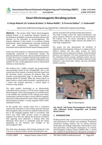
Key Words: Self-Acting Electromagnetic Brake Setup with Enhanced Sensor Integration and ArduinoBasedControl
Braking systems play a crucial role in ensuring the safety and performance of vehicles and machinery. Traditional mechanical braking systems rely on friction between brakepadsandrotatingcomponents,whichleadstowear, heat generation, and frequent maintenance. In contrast, electromagnetic braking systems (EMBS) offer a contact less method of deceleration by utilizing the principles of


Volume:12Issue:05|May2025 www.irjet.net

electromagnetism to generate opposing forces that slow downmotion.Electromagneticbrakesoperatebyinducing eddy currents in a rotating metallic disc or drum when exposed to a magnetic field. These eddy currents produce a magnetic field that opposes the motion of the disc, resulting in a braking effect. Since there is no physical contact, electromagnetic brakes reduce wear, noise, and maintenance costs, making them ideal for high-speed and precision applications such as trains, elevators, wind turbines,andelectricvehicles.
Studies have shown that magnetic brakes can generate a negative power output nearly twice that of a standard engine’s maximum power and at least three times greater than that of an exhaust brake (Reverdin, 1994). These capabilities make magnetic brakes highly effective as supplementary deceleration systems, outperforming many conventional decelerators.
When used as an auxiliary braking system, magnetic brakes significantly reduce the reliance on traditional friction brakes. As a result, the friction components are subjected to less frequent use, preventing them from reaching excessively high temperatures. This extends the lifespan of brake linings and helps to avoid the dangerous issue of ―brake fade.‖
According to research conducted by a truck manufacturing company, magnetic brakes were capable of handling 80% of the braking load that would otherwise be managed by the standard service brakes (Reverdin, 1974). Additionally, magnetic brakes help eliminate the risks associated with prolonged brake usage, particularly the inability to dissipate heat efficiently. This makes them ideal for continuous braking applications, allowing the friction brakes to remain cool and available for emergency use when needed.
Installing an electromagnetic brake is relatively straightforward, provided there is sufficient space between the gearbox and the rear axle. Unlike some braking systems, it does not require a separate cooling unit. Similar to exhaust and hydrokinetic brakes, it utilizes engine components for operation. However, while exhaust brakes function as simple on/off devices and hydrokinetic brakes involve complex control systems, electromagnetic brakes are controlled via a straightforward electric switching mechanism. This provides superior precision and ease of control.


•SystemDesignandAssembly:
The foundation of the electromagnetic braking system begins with the mechanical setup. A standard cycle wheel is modified by attaching a metallic disc, typically made from aluminum or steel, which is ideal for generating eddy currents during braking. This disc rotates along with the wheel and serves as the primary element that interacts with the magnetic field.
To simulate vehicular motion in a controlled environment, a 12V DC motor is employed. The motor is mechanically connected to the cycle wheel through a chain drive system, ensuring a smooth and consistent rotational movement. This setup replicates the movement of a vehicle’s wheel, allowing for accurate testing of the braking mechanism.
Electromagnets are strategically positioned adjacent to the metallic disc, maintaining a minimal air gap to maximize magnetic influence without making physical contact. This non-contact positioning is essential to avoid wear and tear, ensuring durability and longevity of the braking system.


International Research Journal of Engineering and Technology (IRJET) e-ISSN:2395-0056 p-ISSN:2395-0072

Volume:12Issue:05|May2025 www.irjet.net
•ControlLogicIntegration:
The core of the system's intelligence lies in the integration of sensors and a microcontroller. An ultrasonic sensor, such as the JSN-SR04T, is mounted at the front of the setup. This sensor emits ultrasonic waves and measures the time it takes for the echo to return, thereby calculating the distance to any obstacle or object in its path.
The distance data collected by the sensor is transmitted to the Arduino Uno board, a microcontroller based on the ATmega328P. The Arduino processes this information in real time. It is programmed with a specific logic to monitor the sensor readings continuously.
If the Arduino detects an object within a predefined threshold typically set at 1 meter it sends a digital output signal to initiate the braking process. This logic ensures that the system responds automatically and swiftly to potential obstacles, enhancing safety and reliability.
•RelaySwitchingMechanism:
To bridge the gap between the control system and the highpower components, a relay module is introduced. This relay functions as an electronically controlled switch that connects or disconnects the power supply to the electromagnets based on signals received from the Arduino.
The relayoperates under a simple yet effective logic:
When an object is detected within 1 meter: The Arduino sends a HIGH signal to the relay, causing it to close the circuit and supply 12V power from the battery to the electromagnets.
Whennoobjectisdetectedwithin1 meter: The Arduino sends a LOW signal, opening the circuit and cutting off power to the electromagnets, thereby disabling braking.
This switching mechanism ensures precise and efficient control ofthe braking system without manual intervention
•BrakingAction:
The braking process is purely electromagnetic and relies on the fundamental principles of electromagnetism and Lenz’s Law. When the relay activates the electromagnets, a strong magnetic field is produced near the rotating metallic disc.
This magnetic field induces circulating currents known as eddy currents in the conductive material of the disc.
According to Lenz’s Law, these eddy currents create a magnetic field that opposes the change that produced them, in this case, the rotation of the disc.


The opposing force generated by these eddy currents acts against the direction of rotation, effectively reducing the wheel's speed or bringing it to a complete stop. This form of braking is highly efficient, produces no mechanical wear, and operates silently due to the lack of physical contact.
•TestingandOptimization:
To ensure the reliability and efficiency of the electromagnetic braking system, a series of tests are conducted under various conditions. These tests include altering the distance thresholds to evaluate sensor sensitivity, modifying the strength of the electromagnets, and experimenting with different disc materials to analyze their impact on braking performance.
The system's performance is measured using key parameters such as:
Braking response time – the duration between obstacle detection and the actual initiation of braking.
Power consumption – the amount of electrical energy used bythe electromagnet during operation.
Braking effectiveness – the system's ability to reduce or completely stop the wheel's motion.
Based on the test results, iterative improvements are made to optimize the system for maximum safety, efficiency, and energy conservation.
• Principle
The electromagnetic braking system operates on the principle of electromagnetism. When an electric current flows through a circular conductor, it generates a magnetic field around it.
This magnetic field is evenly distributed around the conductor.
The strength of the magnetic field depends on two key factors:
1. The magnitude of the current passing through the conductor.
2.The number of turns inthe coil.
A solenoid, which is essentially a coil with multiple turns, is used to produce a concentrated magnetic field. In electromagnetic braking, the solenoid generates the magnetic flux necessary to induce braking. Increasing the current or the number of coil turns enhances the magnetic field strength, thereby improving the braking efficiency.


International Research Journal of Engineering and Technology (IRJET) e-ISSN:2395-0056 p-ISSN:2395-0072

Volume:12Issue:05|May2025 www.irjet.net
• Objective
PrimaryObjective:
To design and develop a working model of an electromagnetic braking system.
SecondaryObjectives:
1.To gain practical experience in project planning and implementation.
2.To acquire hands-on skills in mechanical fabrication techniques.
3.To leverage technology for enhancing human convenience and improving safety in transportation systems.
3. Literature review
1.P.Hanyecz(1982),“CalculationofBrakingForceinEddy Current Brakes” This foundational work presents theoretical approaches to calculating braking forces in eddy current systems. It emphasizes the physics behind eddycurrentformationandmagneticfieldinteractions.
2. M.A. Heald (1988), “Magnetic Braking: Improved Theory” Heald presents a refinement to earlier magnetic braking models, enhancing their accuracy. Focuses on the limitationsofsimpledragforcemodels.
3. K.D. Hahn et al. (1998), “Eddy Current Damping of a Magnet Moving Through a Pipe”This experimental paper studies a magnet moving in a conducting pipe, measuring dampingforces.Excellentexampleofeddycurrent-induced resistiveforcesinrealsystems.
4. K. Kukutschova et al. (2009), “Wear Mechanism in Automotive Brake Materials...”This paper shifts focus to material science, analyzing wear debris from automotive brakesandenvironmentalconcerns.
5. Der-Ming Ma (2010), “The Design of Eddy-Current Magnet Brakes” This work dives into practical design aspectsofeddycurrentbrakes,fromtheorytoapplication inaerospacesystems.
6.Y.Levinetal.(2006),“ElectromagneticBraking:ASimple QuantitativeModel”
Review: Offers a basic yet quantitative model for eddy currentbraking,focusedoneducationalsimplicity.
7. Sevvel (2014), “Innovative Electro Magnetic Braking System”Describesaconceptualmodelintegratingmodern electromagnetic systems into traditional braking. Emphasizesinnovationandsystemintegration.


8.GigihPriyandoko&M.ZBaharom(2015),“EddyCurrent BrakingExperiment...” Reportsexperimental resultsusing aluminum alloy brake discs. Focuses on material comparisonforbrakingefficiency.
9. A. Aravind et al. (2016), “Eddy Current Embedded Conventional Braking System”Proposes a hybrid braking systemcombiningeddycurrentwithconventionalsystems toenhanceperformance.
4. Required Components & Purpose
ArduinoUno
A microcontroller board based on the ATmega328P, serving as the central control unit. It processes input from sensors and manages the relay to activate braking.
UltrasonicSensor(e.g.,JSN-SR04T)
A waterproof sensor that uses ultrasonic waves to detect the distance of nearby objects. It identifies obstacles ahead of the wheel and sends distance data to the Arduino.
RelayModule(5V,1-Channelor2-Channel)
An electronically controlled switch operated by the Arduino. It turns the electromagnet on or off in response to signals received from the microcontroller.
12VElectromagnet
A coil that produces a magnetic field when energized. It is mounted near the wheel’s metal disc to generate braking force through electromagnetic induction.
12VDCMotor
Supplies rotational movement to the cycle wheel via a chain drive. Used to simulate vehicle motionduring braking tests.
12VBattery
Provides electrical power to the entire system, including the DC motor, electromagnet, and optionally the Arduino. Ensures aconsistent and portable power source.
CycleWheelwithMetalDisc
The rotating component of the setup. A metal disc (typically aluminum or steel) is attached to the wheel and interacts with the electromagnet to generate eddy currents for braking
4.1 Working of the proposed system
The proposed electromagnetic braking system is designed to deliver efficient, contactless braking through the integration of sensor-based automation and fundamental electromagnetic principles. The core of the system lies in its ability to detect obstacles and respond in real time without the need for manual input orphysical contact between braking components.


Volume:12Issue:05|May2025 www.irjet.net

At the heart of the sensing mechanism is an ultrasonic sensor, which continuously emits ultrasonic waves and measures the time taken for the reflected waves to return. By analyzing this data, the sensor accurately calculates the distance between the system and any object directly in front of it. This real-time monitoring ensures that the system remains constantly aware of its environment.
When the sensor detects an object within a predefined threshold typically set at 1 meter it immediately transmits a signal to the Arduino Uno, which functions as the main control unit of the system. The Arduino processes this input and executes the pre-programmed control logic. Upon confirming the proximity of the object, the Arduino activates a digital output pin connected to a relay module.
The relay module, serving as an electronically operated switch, is then triggered by the Arduino. This closes the circuit and connects the 12V DC power supply to the electromagnet, energizing it. Once powered, the electromagnet generates a concentrated and strong magnetic field in its vicinity.
Positioned adjacent to the rotating wheel is a metallic disc, typically made from a conductive material such as aluminum or steel. As this disc spins past the energized electromagnet, the magnetic field induces eddy currents within the metal. In accordance with Lenz’s Law, these induced currents generate their own magnetic field that opposes the motion of the disc. This opposing magnetic force resists the rotation of the wheel, resulting in a smooth and gradual deceleration commonly known as the electromagnetic braking effect.
As long as the object remains within the critical 1-meter range, the system continues to apply the braking force. However, once the obstacle moves away and the distance exceeds the set threshold, the ultrasonic sensor detects the change and sends updated data to the Arduino. The microcontroller then deactivates the output signal, causing the relay to disconnect the power supply to the electromagnet. Consequently, the magnetic field collapses, eddy currents are no longer induced in the disc, and the braking force is removed. This allows the wheel to resume free rotation without resistance.
This automated, contactless braking mechanism significantly enhances safety by providing immediate response to obstacles, while also reducing mechanical wear and tear associated with traditional friction-based braking systems. By eliminating the need for physical contact, the system ensures lower maintenance requirements, longer component life, and a quieter operation. Its intelligent, sensor-driven functionality
makes it a highly suitable solution for modern applications, particularly in smart transportation systems and autonomous vehicle technologies.


p-ISSN:2395-0072

The Electromagnetic Braking System was successfully designed, assembled, and tested. The following results wereobservedduringthetestingphase:
1.Theultrasonicsensoraccuratelydetectedobjectswithin a range of 1 meter and consistently sent signals to the ArduinoUno.
2.The Arduino Uno effectively processed the sensor data andcontrolledtherelaymodulewithoutdelay.
3.The relay successfully acted as a switch, powering the electromagnets when the object was within the set distancethreshold.
4.When the electromagnets were activated, a noticeable braking force was applied to the metallic disc attached to thecyclewheel,slowingdownorstoppingtherotation.
5.Once the object moved beyond the 1-meter range, the electromagnets automatically turned off, allowing the wheeltorotatefreelyagain.
6.The response time of the system was fast and reliable, proving the effectiveness of the design for realtimeapplication
Th The development of the Electromagnetic Braking System showcases an efficient, contactless approach to applying braking force through the principles of electromagnetism and eddy current induction. Utilizing components like an


International Research Journal of Engineering and Technology (IRJET) e-ISSN:2395-0056 p-ISSN:2395-0072

Volume:12Issue:05|May2025 www.irjet.net
ultrasonic sensor, Arduino Uno, relay, and electromagnets, the system enables automatic braking when an object is detected within a preset range. This not only improves safety but also minimizes mechanical wear, offering a dependable and lowmaintenance alternative to traditional braking methods.
Despite certain limitations such as reduced effectiveness at low speeds and dependence on electrical power the system presents opportunities for further refinement and integration. Future advancements like regenerative energy capture and AIpowered obstacle detection could significantly enhance its performance. Overall, this project sets the stage for the evolution of smarter, more sustainable, and intelligent braking technologies for modern transportation and autonomous vehicles.
1.P.Hanyecz,(1982),“CalculationofBrakingforceinEddy current brakes”, Department of Theoretical Electricity. TechnicalUniversityBudapest.
2.M.A.Heald(1988)“Magneticbraking:Improvedtheory”, AmericanJournalofPhysics56:521-2.
3.K.D.Hahn,E.M.Johnson,A.Brokken,&S.Baldwin(1998) "Eddy current damping of a magnet moving through a pipe", American Journal ofPhysics66:1066-66.
4. K. Kukutschovaa, V. Roubiˇceka, K. Malachovab, Z.Pavliˇckovab, R. Holuˇsab, J. Kubaˇckovac, V. Miˇckac, D.MacCrimmond, P. Filip d. 2009. Wear Mechanism in AutomotiveBrakeMaterials,WearDebrisanditsPotential EnvironmentalImpact,InternationalJournalofWear
5. Der-Ming Ma “The Design of Eddy-Current Magnet brakes “December 2010 Department of Aerospace Engineering,TamkangUniversity,Danshuei,Taiwan25137, RepublicofChina
6. Y. Levin, S.L. Da Silveira & F.B. Rizzato (2006) "Electromagnetic braking: A simple quantitative model", American Journal of Physics 74:815-17.
7. Sevvel “Innovative Electro Magnetic Braking System” IJIRSETVolume3,SpecialIssue2,April2014.
8. Gigih Priyandoko, M.Z Baharom, (2015), “Eddy current braking experiment using brake disc from aluminium seriesofA16061andA17075”.
9. A.Aravind, V.R.Akilesh, S.Gunaseelan, S.Ganesh “Eddy currentembeddedconventional braking system” -IJIRSET Volume 5, SpecialIssue7,April2016.


