International Research Journal of Engineering and Technology (IRJET)
e-ISSN: 2395-0056
Volume: 07 Issue: 04 | Apr 2020
p-ISSN: 2395-0072
www.irjet.net
WIRELESS CONTROL AND HARDWARE DESIGN OF SINGLE PHASE SEMI CONTROL RECTIFIER FOR DC SHUNT MOTOR Prof. Pratik Arya1, Harsh Desai2, Vikash Mishra3, Anil Khatua4 1Professor,
Department of EE, MSCET, GUJARAT, INDIA Department of EE, MSCET, GUJARAT, INDIA ---------------------------------------------------------------------***---------------------------------------------------------------------2,3,4Student,
Abstract - This work is carried out with the analysis of speed control of dc shunt motor [1]. We have used semi-controlled rectifier. We are using wireless facilities like Bluetooth, Wi-Fi, GSM module as the wireless communication [2]. Reducing power loss in converter is the part of our motto. The research work is carried with the single phase rectifier. Here we have shown the uncontrolled and controlled circuit of single phase rectifier. By varying the firing angle, we can change the average output voltage which is fed to DC shunt motor. SCRs are used along with the diodes to form the rectifier circuit. Arduino has the role of providing firing pulses to the SCRs [5]. ZCD is used to maintain the synchronism between firing pulses and AC supply [3]. Key Words: SCR, ARDUINO, WIRELESS, DC MOTOR, SPEED CONTROL, RECTIFIER 1. INTRODUCTION Nowadays motors are used almost everywhere, so to control them is really essential task. Energy conservation is the biggest issue through the world. There are numbers of debates going on around the globe as how to save electrical energy. Efficient utilization of energy is the one of the most prominent solution. In a power conversion process the main task is to minimize energy losses and maximize the conversion efficiency. The need of variable dc power supply in power electronics is because of industry`s huge requirement. Rapid improvement in this world has introduced us to latest technology which we can use to modify existing equipment to make human life better. Problem of time management in this era is not new. To solve it in electric engineer`s life we can improve available devices to control them from anywhere anytime.
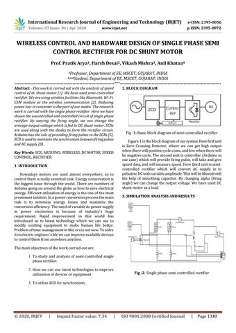
2. BLOCK DIAGRAM
Fig -1: Basic block diagram of semi-controlled rectifier Figure.1 is the block diagram of our system. Here first unit is Zero Crossing Detector, where we can get high output when there will positive cycle come, and low when there will be negative cycle. The second unit is controller (Arduino in our case) which will provide firing pulse, will take and give speed data, and will measure speed. Here third unit is semicontrolled rectifier which will convert AC supply in to pulsative DC with variable amplitude. This will be filtered with the help of smoothing capacitor. By changing alpha (firing angle) we can change the output voltage. We have used DC shunt motor as a load. 3. SIMULATION ANALYSIS AND RESULTS
The main objectives of the work carried out are: 1. To study and analysis of semi-controlled single phase rectifier. 2. How we can use latest technologies to improve utilization of devices or equipment
Fig -2: Single phase semi controlled rectifier
3. To utilize ZCD for synchronism.
Š 2020, IRJET
|
Impact Factor value: 7.34
|
ISO 9001:2008 Certified Journal
|
Page 1348