International Research Journal of Engineering and Technology (IRJET)
e-ISSN: 2395-0056
Volume: 07 Issue: 04 | Apr 2020
p-ISSN: 2395-0072
www.irjet.net
Simulation of Low Cost 50Hz Pulse Generator Shuvajit Pradhan1, Rabindranath Das Adhikary2 1Student,
Department of Electrical Engineering, MODERN INSTITUTE OF ENGINEERING AND TECHNOLOGY, Bandel, India 2Assistant Professor, Department of Electrical Engineering, MODERN INSTITUTE OF ENGINEERING AND TECHNOLOGY, Bandel, India ---------------------------------------------------------------------***----------------------------------------------------------------------
Abstract - This paper is based on Simulation of low cost
50Hz pulse generator. The proposed pulse generator is designed by multivibrator circuit. This pulse generator circuit is designed using 555 timer ic, resistance and capacitor. In the electrical engineering there are many applications where the pulse generator is used. We can use this type of pulse generator in the electrical machine laboratory where we use the the pulse generator or frequency generator to control the speed of 3-phase induction motor. In the industry, there also use pulse generator in many applications. We also can use this pulse generator in many electronics device where different pulse is required because in this pulse generator we can control the frequency.
is describes the percentage of each cycle taken by the active period.[2] Duty cycle={(R1+R2)/(R1+2*R2)}*100
Pulse generator: Pulse generator is an electronics device which generates the pulse normally rectangular pulses. The pulse generator is to provide pulses in many electronics application. In this paper we are going to show the output of the pulse generator will be 50Hz.We also can vary the frequency by using a potentiometer externally. This paper is proposed to make the 50Hz pulse generator[1].
Key Words: Multivibrator, Duty cycle, Pulse generator
1. INTRODUCTION The 555 timer ic is used as IC timer circuit and it is the most commonly used general purpose linear integrated circuit. It can run in two modes: Monostable (one stable state) and Astable (no stable state). A multivibrator circuit behave as a non-sinusoidal oscillator with a regenerative feedback. In the Astable mode the ic produces rectangular waveforms with a variable Duty cycle. An astable multivibrator[3] can be produced by adding resistors and capacitors. The timing which is the output is either high or low is determined by the externally connected resistors and capacitors. Frequency is the number of cycles completed in one cycle and duty cycle is the ratio of the time period of the high state to the time period of low state.
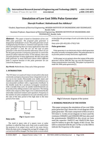
Fig 2: Schematic diagram of the system 2. WORKING PRINCIPLE OF THE SYSTEM
Fig 1: Square wave Duty cycle: The mark to space ratio of a square wave or pulse oscillator is called the Duty cycle. Duty cycle is useful when the purpose of an output wave used to run some device. When the duty cycle is changed the average DC voltage or DC current level will be changed. The Duty Cycle is a term which © 2020, IRJET
|
Impact Factor value: 7.34
|
This paper proposes the simulation of low cost 50Hz pulse generator.Fig:2 shows the circuit diagram of the pulse generator. The main component of this circuit is 555 timer ic. In this circuit diagram we have used the resistance 440Ω(R1) and 220Ω(R2).WE have also used the potentiometer 2KΩ(RV2).In this circuit we have used the capacitor 10uF(C1) and 10nF(C2).We have used 9v battery to give the supply of this circuit. The LED is connected with the pin 3 of the ic to the GND to indicate the frequency in the output.
ISO 9001:2008 Certified Journal
|
Page 1234