International Research Journal of Engineering and Technology (IRJET)
e-ISSN: 2395-0056
Volume: 07 Issue: 04 | Apr 2020
p-ISSN: 2395-0072
www.irjet.net
Design and Performance Analysis of Linear Array S. J. Nandedkar1, S. D. Nawale2 1Asst.
Professor, ETC Department, MIT Aurangabad, Maharashtra Institute of Technology, Aurangabad, (MS), 431005, India 2Professor, N B Navale Sinhgad College of Engineering, Kegaon, Solapur, (MS), 413 255, India ----------------------------------------------------------------------***---------------------------------------------------------------------
Abstract - Abstract—In this paper two and four element arrays are designed using two different substrate materials and their performance is compared. Design is done at 2.4 GHz. Simulated results of four elements array using both material (Arlon AD250 lossy and FR-4) are presented here. It shows that with Arlon substrate better gain and low side lobe levels with adequate bandwidth are achieved. Optimization with Arlon material shows good results. Simulation is done using CST EM simulator. Keywords— Antenna gain, MSA, Return loss , 2.4GHz
In this paper, arrays of Microstrip antenna are analysed using CST simulation tool. Section I gives design equation. Section II describes Microstrip antenna design. Section III elucidates design of multi element antenna with different substrate material and their performance. Finally conclusions of the paper are given in Section IV 2. A MICROSTRIP ANTENNA DESIGN First single patch antenna is designed and then two and four element arrays are designed.
1. INTRODUCTION Massive many input many output antenna array is the need of today’s wireless generation. Requirement of data rate is increasing day by day with miniaturization in antenna size. With increasing requirements for personal and mobile communications, the demand for smaller and low profile antennas has brought the Microstrip antenna to the forefront, [1]. Microstrip antenna are mostly preferred because of its light weight, low volume, low profile, planar configuration, this is possible due to conformal ,low fabrication cost and ease of mass production. Also linear and circular polarizations are possible, [2]. An MSA in its simplest form consists of a radiating patch on one side of a dielectric substrate and a ground plane on the other side. Radiation from the MSA can occur from the fringing fields between the periphery of the patch and the ground plane. In this paper, rectangular patch antenna is designed at a frequency of 2.4 GHz. Two different dielectric materials are used one is low cost commercially available FR4 with dielectric constant 4.4 with loss tangent of 0.025 and another is Arlon AD250 having dielectric constant of 2.5 and loss tangent 0.018. Arlon material combine the excellent low loss electrical properties of Poly Tetra Fluoro Ethylene(PTFE) resin. Stability of PTFE over a wide frequency range and low loss makes it ideal for a variety of microwave and R/F applications in telecom infrastructure, [3]. Antenna array [4][5] is one technique which improves the gain of antenna systems. It is the systematic arrangement of antennas working together for transmitting and receiving waves. It consists of identical antenna elements having identical orientation distributed in space. Based on geometrical configuration antenna arrays are classified as planar array and linear array. For a linear array, the antennas are placed along the Axis (straight line) of the array. © 2020, IRJET
|
Impact Factor value: 7.34
|
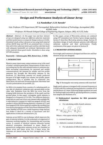
Fig -1: Rectangular microstrip antenna with inset feed Single patch antenna is designed with resonant frequency at 2.4 GHz with FR-4 substrate having dielectric constant of 4.4 and thickness of 1.6mm. Following design equations are used for finding length and width by specifying dielectric constant, loss tangent and thickness of it. 2.1 Mathematical equations for MSA parameter calculations
For calculating width of patch antenna:
Where c =free space velocity of light fr = resonant frequency Ԑr = dielectric constant of substrate
For calculation of effective dielectric constant:
ISO 9001:2008 Certified Journal
|
Page 33