International Research Journal of Engineering and Technology (IRJET)
e-ISSN: 2395-0056
Volume: 07 Issue: 01 | Jan 2020
p-ISSN: 2395-0072
www.irjet.net
THREE AXIS PNEUMATIC AUTOMATIC WELDING MACHINE Pradip Kambale1, Sushant Jawalkar2, Vikram Bhorkade3, Ramkrushna Nimase4, Prof. Sachine Kardile5 5Under
the guidance of Prof. SACHINE KARDILE, HOD, Department of Mechanical Engineering, G. H. Raisoni college of Engineering and Management, Ahmednagar, Maharashtra, India. ----------------------------------------------------------------------***--------------------------------------------------------------------Abstract – In our research replacement of manual effort by the mechanical power. This mechanism introduce to welding the various components automatically. Three pneumatic cylinder and solenoid valve is used. One cylinder used for vertical movement, another one cylinder for arm lifting and one cylinder for the rotary motion by using rack and pinion assembly.
2. MAIN COMPONENETS USED
Key Words: Cylinder-horizontal, vertical, rotary, rack and pinion, solenoid valve, direction control valve, air compressor.
Welding machine
Solenoid valve
Pneumatic double acting cylinders
Rack and pinion gear assembly
Flow control valve
3. PRINCIPLE AND WORKING
1. INTRODUCTION
In our mechanism to achieve automation by using pneumatic power and mechanical arrangement in welding operation. The pneumatic system attractive for low cost, simplicity and less hazardous operations. There are several reasons for considering the use of pneumatic system over hydraulic system.
Automation is important in mass production operations decides the sequence of machining. The machines designed for producing a particular product are called transfer machines. Nowadays all the machines are being atomized in order to product the human being. The automatic machine being atomized for the following reasons,
To achieve high safely operation and increased production rate.
To reduce human involvement in welding operation.
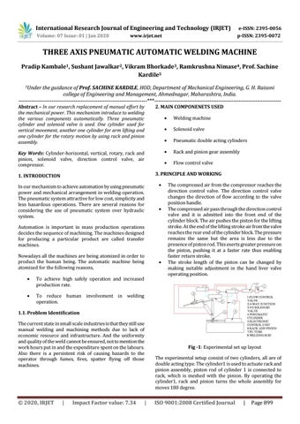
The compressed air from the compressor reaches the direction control valve. The direction control valve changes the direction of flow according to the valve position handle. The compressed air pass through the direction control valve and it is admitted into the front end of the cylinder block. The air pushes the piston for the lifting stroke. At the end of the lifting stroke air from the valve reaches the rear end of the cylinder block. The pressure remains the same but the area is less due to the presence of piston rod. This exerts greater pressure on the piston, pushing it at a faster rate thus enabling faster return stroke. The stroke length of the piston can be changed by making suitable adjustment in the hand liver valve operating position.
1.1. Problem Identification The current state in small scale industries is that they still use manual welding and machining methods due to lack of economic resource and infrastructure. And the uniformity and quality of the weld cannot be ensured, not to mention the work hours put in and the expenditure spent on the labours. Also there is a persistent risk of causing hazards to the operator through fumes, fires, spatter flying off those machines.
© 2020, IRJET
|
Impact Factor value: 7.34
Fig -1: Experimental set up layout The experimental setup consist of two cylinders, all are of double acting type. The cylinder1 is used to actuate rack and pinion assembly, piston rod of cylinder 1 is connected to rack, which is meshed with the pinion. By operating the cylinder1, rack and pinion turns the whole assembly for moves 180 degree.
|
ISO 9001:2008 Certified Journal
|
Page 899