International Research Journal of Engineering and Technology (IRJET)
e-ISSN: 2395-0056
Volume: 06 Issue: 09 | Sep 2019
p-ISSN: 2395-0072
www.irjet.net
Automatic Power Factor Correction Miss Aaiman S Shaikh1, Prof. Laxman S Patil2 1Student
of Department of Electrical Engineering, Padmabhooshan Vasantraodada Patil institute technology, Budhgaon, India 2Associate Professor of Department of Electrical Engineering, Padmabhooshan Vasantraodada Patil institute technology, Budhgaon, India ---------------------------------------------------------------------***----------------------------------------------------------------------
Abstract - A low power factor leads to an increase in losses
and draws penalty by the utility. Modern industry implementing the mechanized methods can suffers from lower power factor due to the use of different electric equipment which requires more reactive power. Significant savings in utility power costs can be understood by keeping up an average monthly power factor close to unity. The above drawback is overcome by the PFC. Power factor correction (PFC) is a technique of reducing the undesirable effects of electric loads that create a power factor which are less than one. In this paper an Automatic Power Factor Correction (APFC) Unit is build which monitors the power factor and automatically it corrects the power factor. Power factor correction is a method of reducing undesirable adverse effects of electric loads that causes a power factor to be less than one. In this t an Automatic Power Factor Correction Unit is build which monitors the power factor and automatically it corrects the power factor. The phase differences between voltage and current are determined using zero crossing detectors with some basic functions of microcontroller. Key Words: power factor, capacitor bank, relay, micro controller, rectifier, current transformer, potential transformer
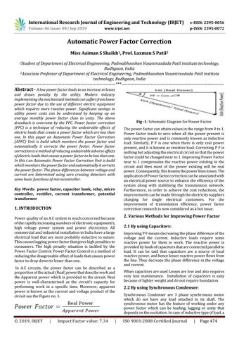
1. INTRODUCTION Power quality of an A.C system is much concerned because of the rapidly increasing numbers of electronic equipment’s, high voltage power system and power electronics. All commercial and industrial installation in India have a large electrical load that are most probably inductive in nature. This causes lagging power factor that gives high penalties to consumers. The high penalty situation is tackled by the Power Factor Control. Power Factor Control is a method of reducing the disagreeable effect of loads that causes power factor to drop down to lesser than one. In A.C circuits, the power factor can be described as a proportion of the actual (Real) power that does the work and the Apparent power which is provided to the circuit. Real power is well-characterized as the circuit’s capacity for performing work in a specific time. Moreover, apparent power is known as the current and voltage product of the circuit see the Figure no. 1.
© 2019, IRJET
|
Impact Factor value: 7.34
|
Fig -1: Schematic Diagram for Power Factor The power factor can attain values in the range from 0 to 1. Power factor tends to zero when all the power present is only reactive power and is commonly known as inductive load. Similarly, P F is one when there is only real power present, and it is known as resistive load. Correcting P F is nothing but adjusting the electrical circuit so that the power factor could be changed near to 1. Improving Power Factor near to 1 compensates the reactive power existing in the circuit and then most of the power existing will be real power. Consequently, this lessens the power lines losses. The application of Power factor correction can be associated with an electrical power source to enhance the efficiency of the system along with stabilising the transmission network. Furthermore, in order to achieve the cost reductions, the improvements can be made through the electricity suppliers charging for single electrical customers. For the improvement of transmission efficiency, power factor correction research is now considered as a hot issue.
2. Various Methods for Improving Power Factor 2.1 By using Capacitors: Improving P F means decreasing the phase difference of the voltage and the current. Inductive loads require some reactive power for them to work. The reactive power is provided by bank of capacitors that are connected parallel to load. It can be said that capacitors are a source of local reactive power, and hence lesser reactive power flows from the line. They decrease the phase difference in the voltage and current. When capacitors are used Losses are low and also requires very less maintenance. Installation of capacitors is easy because of lighter weight and do not require foundation.
2.2 By using Synchronous Condenser: Synchronous Condenser are 3 phase synchronous motor which do not have any load attached to its shaft. The synchronous motor has the feature of working under any power factor which can be leading, lagging or unity that depends on the excitation. In case of inductive type of load, a
ISO 9001:2008 Certified Journal
|
Page 474