International Research Journal of Engineering and Technology (IRJET)
e-ISSN: 2395-0056
Volume: 06 Issue: 09 | Sep 2019
p-ISSN: 2395-0072
www.irjet.net
A Digital Down Converter on Zynq SoC P Sai Hanisha1, M Sailaja2 1Student,
Dept. of ECE, JNTUK, Andhra Pradesh, India Dept. of ECE, JNTUK, Andhra Pradesh, India ---------------------------------------------------------------------***---------------------------------------------------------------------1.1 Digital Down Conversion Model Abstract - A typical communication system requires a 2Professor,
receiver consisting of a digital down converter which mixes and down samples the received high sampled data for easy processing. The DDC developed in this work is for Air Borne radar receivers. When compared to all the signal processing techniques involved in a radar receiver, the performance of a DDC is significant in extraction of target data. To maximize the performance of DDC, the implementation is done on a System on Chip (SoC) which meets the flexibility of a processor and programmability of a FPGA. In this work, a DDC is developed with two stage decimation and filtering. The order and type of the filters were optimally designed for efficient resource utilization. Additionally, a digital synthesizer is developed and taken as inputs for the DDC. This work presents a complete DDC model with optimized decimation and filtering stages in comparison with different implementations. Key Words: Digital Down Converter, System On Chip, FPGA, LFM, Direct Digital Synthesizer, FIR filter
1. INTRODUCTION A digital down converter takes a band limited high sample rate digitized signal, mixes to a lower frequency and down samples to a required sample rate with efficient filtering. The Digital Down Converter (DDC) has become the cornerstone technology for all the existing communication systems. Over the past several years, there was tremendous development in the digital signal processing systems in terms of flexibility, processing capability and power consumption. So the implementations of the DDCs have started on several platforms like DSPs, GPUs, ASICs and FPGAs by improving their performances. The work presented in [1] has developed a multi-channel IF signal processing DDC based on a DSP but has issue with signal synchronicity. The GPU based implementation [2] could not meet the speed and programmability. The ASIC based implementation [3] could achieve the advantages a FPGA. The novel architectures provided in [4], [5], [6], [7] and [8] are appreciated but they could not the meet the specifications of air borne radars, where there is a requirement of compact on-field programmable devices. So the architecture designed and implemented in this paper consisted a optimal solution for the digital down conversion of air borne radar receivers. The model also presented a waveform generation which can be used as a input for the down conversion chain.
Š 2019, IRJET
|
Impact Factor value: 7.34
|
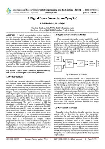
When compared to its analog counterpart, DDC is widely used in the recent radar receivers for its stability and consistency in amplitude and phase of the output signals. A DDC achieves this by Mixing to shift the signal spectrum from the selected carrier frequencies to baseband, Decimation to reduce the sample rate and Filtering to remove adjacent channels, minimize aliasing, and maximize the received signal-to-noise ratio (SNR) DDS (LFM) Complex multiplicat ion
2-stage filtering,de cimation
I and Q Splitter
I Q
DDS (Carrier)
Fig -1: Proposed DDC Model Generally, the IF received after LNA and IF amplification will be beaten with a carrier signal which is synchronized with transmitter pulse. The required baseband signal is extracted by this mixing operation and is given to a low pass filter to extract the desired down converted frequencies. The resultant signal is then decimated to a lower sampling rate with required decimation rate. But in this model, the high sampled IF is generated using a synthesizer to check the operation of the system. This synthesizer can be used in the transmitter part when it is typically implemented. The proposed architecture is the basic implementation model which used DDS, complex multiplier and FIR filter stages which included decimation.
1.2 Waveform Generation In a radar system, the choice of a radar waveform plays an crucial role in detecting the target. The transmitter synthesizes the high bandwidth data with selected pulse compression techniques for efficient detection. The pulse compression technique used in this paper is Linear Frequency Modulated Wave (LFM). It is generated at a pass band with high sampling rate with the help of control logic developed in this work. In radar applications, linear chirp is the most typically used signals to achieve pulse compression. In LFM, the frequency linearly increases or decreases across the pulse. The instantaneous phase of the chirp signal is expressed as:
ISO 9001:2008 Certified Journal
|
Page 1472