International Research Journal of Engineering and Technology (IRJET)
e-ISSN: 2395-0056
Volume: 06 Issue: 04 | Apr 2019
p-ISSN: 2395-0072
www.irjet.net
Bridgeless Boost PFC Rectifier with High Efficiency S. Venkatesh1, D. Sarveswararao2, G.S. Nikhitha3, Sk. Mehanaz4 1Assistant
Professor, KKR&KSR Institute of Technology & Sciences, Guntur Member KKR&KSR Institute of Technology & Sciences, Guntur ---------------------------------------------------------------------***---------------------------------------------------------------------1.1 Traditional full bridge PFC rectifier Abstract - For the conventional PFC rectifiers, the high 2,3,4Student
efficiency cannot be achieved over a wide input range, and the efficiency will be greatly decreased at low input voltages. In order to overcome the efficiency bottleneck under low line input, a flexible mode bridgeless boost power factor correction (PFC) rectifier is proposed . According to the input voltage, the proposed rectifier can be flexibly adapted to the suitable operating mode to obtain the maximum efficiency. Meanwhile, the circuit components can be reused by different operating modes, so the extra cost is low. In the proposed rectifier, a back-to-back bridgeless boost PFC topology is adopted at high line conditions and a three-level bridgeless boost PFC topology is rebuilt to reduce the switching losses at low line conditions. Compared with the traditional bridgeless boost PFC rectifier, an extra low-voltage bidirectional switch (usually composed of two switches) is added, so the increased cost is low. In addition, the low common mode noise can be achieved at both high and low line conditions due to the direct connection between the input mains and the output electrolytic capacitor. The detailed principle analysis about the proposed rectifier is presented in this paper. Finally, an experimental prototype is built to verify the feasibility and the effectiveness of the proposed topology
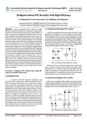
The key principle that drives the boost converter is the tendency of an inductor to resist changes in the current. When being charged it acts as a load and absorbs energy (somewhat like a resistor); when being discharged it acts as an energy source (somewhat like a battery). The voltage it produces during the discharge phase is related to the rate of change of current, and not to the original charging voltage, thus allowing different input and output voltages.The traditional full bridge rectifier is shown in fig1.1
Fig 1.1 Traditional full bridge PFC rectifier The Power factor correction using boost converter can be used to attain a decent power factor along with some advantages such as higher output voltage, light and less bulky as compared to capacitor banks used for PFC, the output voltage can be stepped down as per the requirement using chopper circuit preceding the PFC circuit.
Key Words: bridgeless PFC, flexible mode, high efficiency, low common mode noise.
1. INTRODUCTION
1.2 Dual boost bridgeless PFC rectifier
In order to meet the harmonic regulations and standards, such as the power supplies with active power factor correction (PFC) feature are required for various types of electronic equipment. Meanwhile, the increasing requirements of high efficiency have been forcing the designers to look for any potential opportunities to reduce the converter losses. The most common solution is the conventional PFC rectifier which is widely used for various kinds of computers, workstations, servers and so on. However, it suffers from high conduction losses since the input current always flows through two bridge diodes and a power switching device. Besides, the efficiency decrease caused by conduction losses is more obvious when the input line voltage is low, which usually leads to low power density since a large heat sink is needed. In order to overcome the shortcomings of the conventional PFC converter
In these boost bridgeless PFC rectifiers, the most practical and potential to-pologies are the dual-boost bridgeless PFC rectifier (DBBL PFC) shown in Fig.1.2 and the back-to-back bridgeless PFC rectifier (BTBBL PFC) shown in Fig. 1.3.
Fig 1.2 Dual boost bridgeless PFC rectifier
Š 2019, IRJET
|
Impact Factor value: 7.211
|
ISO 9001:2008 Certified Journal
|
Page 3741