International Research Journal of Engineering and Technology (IRJET)
e-ISSN: 2395-0056
Volume: 06 Issue: 12 | Dec 2019
p-ISSN: 2395-0072
www.irjet.net
Five Level inverter based Single Phase to Three Phase Converter Anirban Giri1, Dipanjan Mondal2 1Student,
Department of Electrical Engineering, MODERN INSTITUTE OF ENGINEERING & TECHNOLOGY, Bandel, India 2Student, Department of Electrical Engineering, MODERN INSTITUTE OF ENGINEERING & TECHNOLOGY, Bandel, India ----------------------------------------------------------------------***---------------------------------------------------------------------
Abstract – This paper proposes a five level inverter based
single phase supply to three phase supply conversion system. This converter is able to run any three phase equipment from a single phase supply. Lower distortion of the output ensure about better performance and lower ripple in equipments output. Using capacitor based voltage divider system in inverter reduces the number of switches and improves the system efficiency. This converter allows to run three phase equipment at the same frequency of single phase. Key Words: transformer
effect. Reference signal of PWM generator is taken from the single phase source so the output should be same as the input frequency.
Rectifier, PWM, THD, Inverter, Isolation
1. INTRODUCTION
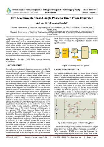
Fig -1: Block Diagram of the system
Nowadays most of electrical equipments are operated by AC power. Starting current of a three phase motor is less than a same rating single phase motor starting current. Three phase motor are preferred more than a single phase motor in industrial application due to its low ripple in output and better performance. For heavy duty and higher power rating three phase motors are used. It is very difficult to get three phase supply in everywhere. In some rural area where low density of consumers presents typically the three phase power is not supplied due to higher installation cost and maintenance cost of transmission line. In this type of cases and in some remote area single phase power is supplied. In this type of condition to run three phase equipments this proposed converter should be applicable. This converter is based on rectifier, filter, and inverter system. To run an induction motor from inverter Total Harmonics Distortion (THD) should be lower for better performance and lower ripple in mechanical output of the motor. To reduce THD mainly Pulse width modulation (PWM) and multilevel topology is used in this project. By using both topologies in this project THD should decrease better and output waveform should be sinusoidal. Three phase Inverter is builded by the combination of three single phase inverters which are connected with the three phase load by a isolated winding three phase transformer. Without using isolation transformer it is very difficult to get the neutral point because all the inverters –ve terminal are not in same potential at every instant of time so no common terminal should be find out. By using isolation transformer all the primary windings should be separated but the secondary can be connected in star. Transformer is not only works as a isolation device it is also working as a filter by its inductive
2. WORKING OF THE SYSTEM
© 2019, IRJET
ISO 9001:2008 Certified Journal
|
Impact Factor value: 7.34
|
This proposed system is based on single phase AC to DC conversion and DC to three phase AC conversion. Single phase AC supply by using bridge rectifier converted to DC and it is filtered for better performance. From the rectifier output by the help of three inverter it is converted into three phase AC. Three inverter are supplied ac power to primary winding of isolation transformer. In isolation transformer all three primary windings are isolated. So all the three inverter should be isolated. It is possible to connect the secondary winding and load in star or delta to supply three phase power to the load. For transformer inductive effect it is working as a filter which makes output more accurate.
Fig -2: Schematic diagram of the inverter/phase
Inverter is designed by combination of three single phase inverter. Switch of inverters are controlled by PWM generator. PWM generator is designed by comparison of triangular wave and input sine wave. |
Page 1296