International Research Journal of Engineering and Technology (IRJET)
e-ISSN: 2395-0056
Volume: 05 Issue: 03 | Mar-2018
p-ISSN: 2395-0072
www.irjet.net
MODELING OF WANKLE ENGINE AND STEADY STATE THERMAL ANALYSIS ON CYLINDER NARISE VENKATESH1, RAJESH CVS2, DOMMETI SRINIVASA RAO3 1,2,3Asst
professor,department of Mechanical Engineering,Avanthi Institute of Engineering & Technology, Vizianagaram, Andhra Pradesh, India ---------------------------------------------------------------------***---------------------------------------------------------------------
Abstract - This project is aims to design of wankle engine
and steady state thermal analysis on cylinder. This is invented by German engineer Felix wankle, is a type of internal combustion engine which uses a rotary design to convert pressure energy into a rotary motion instead of using reciprocating pistons. Its four-stroke cycle takes place in a space between the inside of an oval-like epitrochoid-shaped housing and a rotor that is similar in shape to a Reuleaux triangle but with sides that are somewhat flatter. This design delivers smooth high- rpm power from a compact size. Since its introduction the engine has been commonly referred to as the rotary engine, though this name is also applied to several completely different designs.
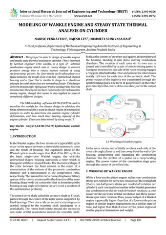
Seals at the corners of the rotor seal against the periphery of the housing, dividing it into three moving combustion chambers. The rotation of each rotor on its own axis is caused and controlled by a pair of synchronizing gears. A fixed gear mounted on one side of the rotor housing engages a ring gear attached to the rotor and ensures the rotor moves exactly 1/3 turn for each turn of the eccentric shaft. The power output of the engine is not transmitted through the synchronizing gears. The force of gas pressure on the rotor goes directly to the centre of the eccentric, part of the output shaft.
The CAD modeling software CATIA V5R19 is used to visualize the models for the chosen design in addition, the finite element modules is used to obtain results of mechanical analysis in order to determine the wankle engine cylinder deformation, and how much heat bearing capacity of the engine cylinder. These are determined by using ansys15. Key Words: Ansys15,CATIA V5R19, Epitrochoid, wankle engine
1. INTRODUCTION In the Wankel engine, the four strokes of a typical Otto cycle occur in the space between a three-sided symmetric rotor and the inside of housing. The expansion phase of the Wankel cycle is much longer than that of the Otto cycle. In the basic single-rotor Wankel engine, the oval-like epitrochoid-shaped housing surrounds a rotor which is triangular with bow-shaped flanks. The theoretical shape of the rotor between the fixed corners is the result of a minimization of the volume of the geometric combustion chamber and a maximization of the compression ratio, respectively. The symmetric curve connecting two arbitrary apexes of the rotor is maximized in the direction of the inner housing shape with the constraint that it doesn’ttouchthe housing at any angle of rotation (an arc is not a solution of this optimization problem). The central drive shaft, called the eccentric shaft or E-shaft, passes through the center of the rotor and is supported by fixed bearings. The rotors ride on eccentrics (analogous to cranks) integral to the eccentric shaft (analogous to a crankshaft). The rotors both rotate around the eccentrics and make orbital revolutions around the eccentric shaft. Š 2018, IRJET
|
Impact Factor value: 6.171
|
1.1 Working of wankle engine. As the rotor rotates and orbitally revolves, each side of the rotor is brought closer to and then away from the wall of the housing, compressing and expanding the combustion chamber like the strokes of a piston in a reciprocating engine. The power vector of the combustion stage goes through the center of the offset lobe.
2. WORKING OF WANKLE ENGINE While a four-stroke piston engine makes one combustion stroke per cylinder for every two rotations of the crankshaft (that is, one-half power stroke per crankshaft rotation per cylinder), each combustion chamber in the Wankel generates one combustion stroke per each driveshaft rotation, i.e. one power stroke per rotor orbital revolution and three power strokes per rotor rotation. Thus, power output of a Wankel engine is generally higher than that of a four-stroke piston engine of similar engine displacement in a similar state of tune; and higher than that of a four-stroke piston engine of similar physical dimensions and weight. ISO 9001:2008 Certified Journal
|
Page 107