International Research Journal of Engineering and Technology (IRJET)
e-ISSN: 2395 -0056
Volume: 04 Issue: 05 | May -2017
p-ISSN: 2395-0072
www.irjet.net
A review on fatigue behaviour of connecting rod made of Austempered Ductile Iron Prashant S. Tripathi1, P. Frank Crasta2 1Student,Mechanical Engineering, D. J Sanghvi College of Engineering,Maharashtra,India. Asst. Professor, Dept. of Mechanical Engineering, D. J Sanghvi College of Engineering,Maharashtra,India. ---------------------------------------------------------------------***--------------------------------------------------------------------2
Abstract – This article is a review of the fatigue behavior of connecting rod made of Austempered ductile iron (grade 1050) . It is estimated that 50-90% of structural failure is due to fatigue . Due to cyclic loading and presence of stress concentrations at the critical areas, fatigue becomes the primary cause of failure of connecting rods. A literature review on several relevant aspects of this work is also provided. The parametric model of connecting rod was modeled using CATIA V5 R20 which was then later imported to ANSYS 15.0, a Finite Element Analysis tool. Also this project includes a comparison of fatigue behavior of ADI with AISI 4340 steel ,a medium carbon low alloy steel. Stress Life (SxN) theory was used to carry out the fatigue analysis. The focus of fatigue in ANSYS is to provide useful information to the design engineer when fatigue failure may be a concern.
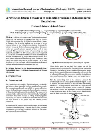
Fig -1:Main motions of piston-connecting rod system These holes must be parallel. The upper end of the connecting rod is connected to the piston by the piston pin. The upper end is forced to turn back and forth on the piston pin as the lower end of the connecting rod revolves with the crankshaft. Although this movement is slight, the bushing is necessary because of the high pressure and temperatures.
Key Words: Fatigue, Stress, Austempered ductile Iron, Catia V5 R20, Ansys 15.0, Finite Element Analysis , Stress Life theory
1. INTRODUCTION
For the connecting rod to be clamped around the crankshaft,the lower hole is splitted. The bottom part, or cap, is made of the same material as the rod and is attached by two bolts. A bearing material in the form of a separate split shell is the surface that bears on the crankshaft. The two parts of the bearing are positioned in the rod and cap by dowel pins, projections, or short brass screws. Split bearings may be of the precision or semi precision type.
1.1 Connecting Rod The connecting rod connects the piston to the crankshaft, and consists of the crank(big end),pin (small end),and shank. The connecting rod small end, which is connected to the piston via the piston pin, transmits the combustion pressure of the cylinder to a force on the crank pin. The crank pin is eccentric to the rotational axis of the crankshaft, resulting in a moment force that induces a rotary motion(Fig.).The connecting end is thus a mechanical element that transforms the axial motion of the piston into the rotation of the crankshaft. A connecting rod consists of a pin-end, a shank section, and a crank-end as shown in Fig 1.1.To permit accurate fitting of bearings the pin-end and crank-end pinholes at the upper and lower ends are machined.
Fig-2: Schematic of a typical connecting rod (Schreier, 1999).
Š 2017, IRJET
|
Impact Factor value: 5.181
|
ISO 9001:2008 Certified Journal
|
Page 2691