International Research Journal of Engineering and Technology (IRJET)
e-ISSN: 2395 -0056
Volume: 04 Issue: 05 | May -2017
p-ISSN: 2395-0072
www.irjet.net
Design and Implementation of Fuel Metering Unit for an Aero Engine SWEETY.S1, SWETHA KUMARI.U2, VINITH PRABHU.H3 SUPRIYA.K.V4 UG Student, Department of Electronics and Communication Engineering, Dr.T.T.I.T, K.G.F, India1,2,3. Assistant Professor, Department of Electronics and Communication Engineering, Dr.T.T.I.T, K.G.F, India4 ---------------------------------------------------------------------***---------------------------------------------------------------------
Abstract - In this novel we design a program using Labview software is designed and implemented on a FPGA system to control the fuel flow of an Aero engine. Fuel flow of an engine varies with an ambient condition such as temperature, pressure and the amount of fuel flow to the engine is different at various altitudes. Fuel system is one of the most important subsystems of aircraft and engine control unit which forms the base for fuel control. Our aim is to develop a closed loop control system which responds to the subsequent changes or disturbance in the system environment such as speed, temperature and pressure sensors are used to sense these ambient conditions, which is compared with the desired operating parameters and allow the user to set the desired operating state as a reference and also allow the control unit to control the Fuel system to the desired operating point with the help of NI based controller with FPGA processor.
Before Electronic Control Unit(ECU), air /fuel mixture, ignition timing and idle speed were mechanically set and dynamically controlled by mechanical and pneumatic means. An ECU commonly known as “Power train control module” (pcm), that controls a series of actuators on an internal combustion engine to ensure optimal engine performance. Depending upon the type of engine control system, its function may also include holding the engine speed at specific constant levels such as idle rpm or maximum/minimum speeds within a specific band or the entire range between idling and maximum speed [3].
II. METHODOLOGY
Personal Computer
Key Words: FPGA, Fuel Flow Control, Stepper Motor, etc…
FPGA Processor
DIO Board
I. INTRODUCTION In this paper our main Aim is to design an Aero Engine Control System [2] for controlling Fuel Flow to the combustion chamber by using Stepper Motor, to control the speed of plane by monitoring critical Exhaust temperature and Compressor pressure. Stepper motor has many advantages then other types of motors, most important is rotates accurate angles or step based on command pulses. The speed of stepper motor can be readily controlled based on the pulse, enable stepping motor to achieve the variable speed synchronous movement of load is directly coupled to drive shaft of motor. For particular application of stepper motor and electromechanical actuator, the stepper motor size is selected and is determined by the nominal operating load range encountered. The stepper motor is capable of receiving the digital signals and is to generate a corresponding angle variation in proportion to total number of pulses, the stepping motor is driven by an open loop without utilizing a feedback mechanism. Therefore, the stepping motor can be easily controlled when stepping motor is driven to achieve a rotational speed within acceptable range. For smooth functioning of engine, it is highly desirable to provide a reliable speed regulation and over speed protection mechanism of engine. Aero engine is extremely reliable when properly varied they can deliver years of safe light [1] © 2017, IRJET
|
Impact Factor value: 5.181
|
Stepper Motor Driver Circuit
Temp Sensor
Pressure sensor
Signal Conditioning
AIO Board
28V
Stepper Motor
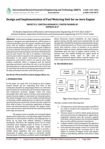
Fig-1: Block Diagram of the System The Fig 1 consists of the following units 1. 2.
3. 4.
A Temperature sensor (thermocouples and RTD’s) are used to measure the temperature of various parts of engine. Pressure sensor is a device which senses pressure and converts it into an analog electric signal whose magnitude depends upon the pressure applied, since they convert pressure into an electrical signal, they are also called as pressure transducers. A signal condition which manipulates the signal in a way that prepares it for the next stage of processing. Fuel metering unit stepper motor is to control the speed by monitoring the incoming fuel to the engine. It consists of stepper motor and stepper motor is controlled by software control law’s using labview.
ISO 9001:2008 Certified Journal
|
Page 2486