International Research Journal of Engineering and Technology (IRJET)
e-ISSN: 2395 -0056
Volume: 04 Issue: 05 | May -2017
p-ISSN: 2395-0072
www.irjet.net
4-Bit Full Adder Using 1-Bit Hybrid 13T Adder SHARADA M. RANE1, SAGAR S. PATHAK2, PRIYANKA A. KHARCHE3, D. S. PATIL4 1,2,3Pursuing
M. Tech, Dept. of Electronics Engineering & Technology, NMU, Maharashtra, India. Electronics and Engineering, NMU, Maharashtra, India ---------------------------------------------------------------------***--------------------------------------------------------------------4Professor, Dept. of
Abstract - The focus of researchers throughout the years is
certain performance aspect. Therefore, the trend now is using hybrid logic approach which mixed many logic styles in improving the total act of the full adder. In [5] a 1-bit full adder is designed using 20 transistors over the hybrid approach. This full adder has a good characteristic in term of speed and power; but the disadvantage of this design is it depends on the modified semi XOR-XNOR gates which are not able to generate a full swing waveform for all its output. Uniform though this design offers significant improvement in terms of power and speed, the drawback is it consumes larger area than some other designs. The low power and high speed aim is doable by this design by eliminating an inverter and matching its delay. However, the adder circuit also produced incomplete voltage swing. Hence this paper is proposing a novel 1-bit hybrid full adder (HFA) circuit using 13 transistors (13T) that will able to achieve the desired target.
a quest of designing low power and high speed adder. Addition is one of the fundamental arithmetic operations and is used extensively in many signal processing system and the heart of arithmetic logic unit (ALU). Several logic styles have been used in the past to design a full adder (FA) with the least power consumption and delay, and each design has its own advantages and disadvantages. Most of the new FA circuits were proposed using less number of transistors with less delay and low power requirement but different logic tend to prefer certain performance aspect. The usual 1-bit 28 transistors FA of standard courtesy style-based has the advantages of strength against voltage scaling and has regular layout but it requires high input capacitance. Therefore, the trend now is using hybrid logic approach which mixed various logic styles in improving the overall performance of the full adder. A 1-bit full adder is designed using 20 transistors through the hybrid approach. This full adder has a good characteristic in term of speed and power; but the weakness of this design is it depends on the modified semi XOR-XNOR gates which are not able to generate a full swing waveform for all its output. Even though this design offers significant improvement in terms of power and speed, the drawback is it consumes larger area than some other designs. The low power and high speed aim is achievable by this design by removing an inverter and balancing its delay. However, the adder circuit also produced incomplete voltage swing. Hence this project is proposing a 1-bit hybrid full adder (HFA) circuit using 13 transistors (13T) that will able to achieve the desired target. The proposed 4-bit adder is implemented using Tanner EDA tool.
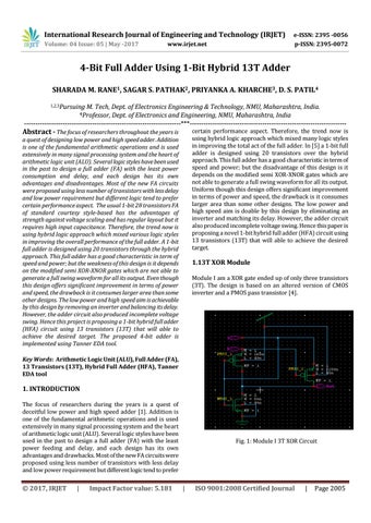
1.13T XOR Module Module I am a XOR gate ended up of only three transistors (3T). The design is based on an altered version of CMOS inverter and a PMOS pass transistor [4].
Key Words: Arithmetic Logic Unit (ALU), Full Adder (FA), 13 Transistors (13T), Hybrid Full Adder (HFA), Tanner EDA tool
1. INTRODUCTION The focus of researchers during the years is a quest of deceitful low power and high speed adder [1]. Addition is one of the fundamental arithmetic operations and is used extensively in many signal processing system and the heart of arithmetic logic unit (ALU). Several logic styles have been used in the past to design a full adder (FA) with the least power feeding and delay, and each design has its own advantages and drawbacks. Most of the new FA circuits were proposed using less number of transistors with less delay and low power requirement but different logic tend to prefer
Š 2017, IRJET
|
Impact Factor value: 5.181
Fig. 1: Module I 3T XOR Circuit
|
ISO 9001:2008 Certified Journal
|
Page 2005