International Research Journal of Engineering and Technology (IRJET) Volume: 04 Issue: 05 | May -2017
www.irjet.net
e-ISSN: 2395 -0056 p-ISSN: 2395-0072
Solar Rescue Robot Gayathri Hari1, Mariya Roy2, Roopa Ann Mathew3 and Bose Mathew Jos4 1,2,3Student,
Dept. Of Electrical and Electronics, Mar Athanasius College of Engineering , Kerala, India Dept. Of Electrical and Electronics, Mar Athanasius College of Engineering , Kerala, India ---------------------------------------------------------------------***--------------------------------------------------------------------4Professor,
Abstract - The project is developed mainly for the rescue operation using a robotic vehicle powered by solar energy. The robotic vehicle is controlled wirelessly for remote operation. The main advantage over the existing robot is that it uses solar charging battery. At the transmitting end Zigbee device is used, control commands are sent to the receiver, to move the robot in all for directions, that is either backward, forward, left or right. Body movement is controlled by the two motors at the receiving end interfaced to the microcontroller. The main advantage of this robot is to sent the corresponding signal to the controller when a disastrous situation is detected. The advantage of the adequate range is provided by the Zigbee device application transmitter which acts as a remote controller, while its receiver end is fed to the microcontroller to drive the DC motors using a motor driver IC for necessary work. The project also has an wireless camera which is interfaced so that the person controlling it can view the operation. Apart from this, it also contains several sensors like the gas sensor for gas detection, temperature sensor to detect the temperature, human detection sensor or the PIR to detect the presence of humans, fire sensor for fire detection.
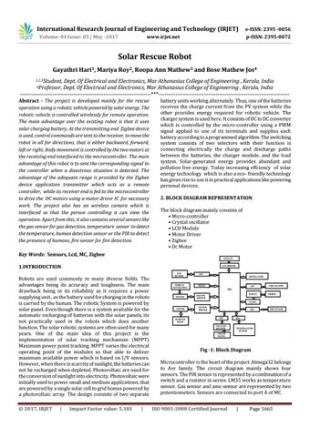
battery units working alternately. Thus, one of the batteries receives the charge current from the PV system while the other provides energy required for robotic vehicle. The charger system is used here. It consists of DC to DC converter which is controlled by the micro-controller using a PWM signal applied to one of its terminals and supplies each battery according to a programmed algorithm. The switching system consists of two selectors with their function is connecting electrically the charge and discharge paths between the batteries, the charger module, and the load system. Solar-generated energy provides abundant and pollution free energy. Today increasing effciency of solar energy technology which is also a eco- friendly technology has given rise to use it in practical applications like powering personal devices. 2. BLOCK DIAGRAM REPRESENTATION The block diagram mainly consists of • Micro-controller • Crystal oscillator • LCD Module • Motor Driver • Zigbee • Dc Motor
Key Words: Sensors, Lcd, MC, Zigbee 1.INTRODUCTION Robots are used commonly in many diverse fields. The advantages being its accuracy and toughness. The main drawback being in its reliability as it requires a power supplying unit , as the battery used for charging in the robots is carried by the human. The robotic System is powered by solar panel. Even though there is a system available for the automatic recharging of batteries with the solar panels, its not practically used in the robots which does another function. The solar robotic systems are often used for many years. One of the main idea of this project is the implementation of solar tracking mechanism (MPPT) Maximum power point tracking. MPPT varies the electrical operating point of the modules so that able to deliver maximum available power which is based on I/V sensors. However, when there is scarcity of sunlight, the batteries can not be recharged when depleted. Photovoltaic are used for the conversion of sunlight into electricity. Photovoltaic were initially used to power small and medium applications, that are powered by a single solar cell to grid homes powered by a photovoltaic array. The design consists of two separate © 2017, IRJET
|
Impact Factor value: 5.181
|
Fig -1: Block Diagram Microcontroller is the heart of the project. Atmega32 belongs to Avr family. The circuit diagram mainly shows four sensors. The PIR sensor is represented by a combination of a switch and a resistor in series. LM35 works as temperature sensor. Gas sensor and ame sensor are represented by two potentiometers. Sensors are connected to port A of MC ISO 9001:2008 Certified Journal
|
Page 1665