International Research Journal of Engineering and Technology (IRJET)
e-ISSN: 2395 -0056
Volume: 04 Issue: 05 | May -2017
p-ISSN: 2395-0072
www.irjet.net
Bandwidth Enhancement Using Single Slot in Heptagonal Microstrip Patch Antenna Mahendra Singh Menea Assistant Professor, Department of Electronics and Communication Engineering, Amity School of Engineering and Technology, Amity University Haryana, India ---------------------------------------------------------------------***---------------------------------------------------------------------
Abstract - FR4 is an inexpensive and easily available
substrate material, which can be used to design efficient and cost effective microstrip patch antenna. This paper focuses on increasing the bandwidth of the microstrip patch antenna. Paper discusses about design of a Heptagonal patch antenna, having coaxial probe as a feed. To get the improved bandwidth, a rectangular slot has been digged on the patch, which changes the interaction of radiation. A huge increase in bandwidth is observed using the proposed design. All the simulation work is done using IE3D simulating software from Zeland has been used. Key Words: FR4, heptagonal antenna, slot, coaxial feed, IE3D
1. INTRODUCTION ( Size 11 , cambria font) A Microstrip or Patch Antenna is a low profile Antenna that has a number of advantages over other antennas. It is lightweight, inexpensive, and easy to integrate with accompanying electronics. While the antenna can be 3D in structure (wrapped around an object, for example), the elements are usually flat, hence their other name, Planar Antennas. A Planar Antenna is not always a patch antenna. But the use of conventional elliptical microstrip patch antenna alone is very difficult because of its low gain and narrow bandwidth. So to overcome these problems various methods have been tried, some of them are listed in next section. This paper proposes a method in which slots are digged in heptagonal patch antenna. Configuration of paper is as follows: Next section is literature review, which is followed by proposed design and in the last some conclusions are drown based on simulation done.
2. Literature Review The Gordon et.al described that the band width of microstrip antennas can be increased by using thick substrate but with thick substrate coaxial probe feed introduces inductive component due to which unavoidable impedance mismatch occurs. So the solution to impedance mismatch was found in the form of capacitive feeding mechanism which can be used for annular ring MPA elements, consisted a small capacitor patch in the same layer as in the radiating element. [1] Gordon et.al experimented on following three designs:
Rectangular radiating elements, Circular radiating elements and Annular ring radiating elements
the small patch. Design tool used was IE3D 12th version Zeland, substrate was FR4 with thickness 1.6 mm having dielectric constant 4.4. Height of patch from ground was taken as 15 mm, ground plane was taken as square of 150x150 mm and probe diameter 0.9 mm. Experimental Results are shown below: Resonant frequency- 1800MHz 10 dB return loss Band WidthRectangular
Circular
Annular Ring
Simulated
25.9%
26.8%
25.9%
Measured
26.4%
27.9%
26.1%
GainRectangular
Circular
Annular Ring
Simulated
8.5dBi
8.8 dBi
8.0 dBi
Measured
8.2 dBi
8.6 dBi
8.5 dBi
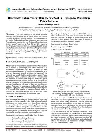
Fig- 1: Structure of proposed antenna design for (a) rectangular,(b) circular and (c) annular ring radiating elements (d) side view of anteena. Dheeraj et. al. proposed modified circular patch antenna to achieve 50.36% efficiency together with 4.10 dBi gain and 8.38% band width. Firstly they taken a circular patch and then an elliptical slot has been cut in it, after this, parallel to major axis of the inserted elliptical slot, splitting is applied and at last this elliptical hole is filled with an elliptical patch between two split halves of circular patch. FR4 of thickness 1.59 mm and dielectric constant 4.4 was taken as substrate which had loss tangent of 0.0148. Main circular patch radius was taken 12 mm. For inside elliptical patch semi major axis is of 9 mm, semi minor axis is of 4.8 mm and eccentricity is 0.846. Splitting width of circular patch in two halves is 0.25 mm. Ellipse filling the elliptical slot has a = 8 mm and b = 3 mm.
Feeding mechanism was common in all three designs. The position of the probe feed was decided to be in the center of © 2017, IRJET
|
Impact Factor value: 5.181
|
ISO 9001:2008 Certified Journal
|
Page 1416