International Research Journal of Engineering and Technology (IRJET) Volume: 03 Issue: 08 | Aug-2016
www.irjet.net
e-ISSN: 2395 -0056 p-ISSN: 2395-0072
Fatigue Failure Analysis of Rim Kunal H. Borase1, Dr. E.R.Deore2 1 PG Student, Mechanical Engineering Department, S.S.V.P.S.’s. B.S.D. Dhule ,Maharastra, India 2 Prof., Mechanical Engineering Department, S.S.V.P.S.’s. B.S.D. Dhule ,Maharastra, India ------------------------------------------------------------------------------------------------------------------------------------------------
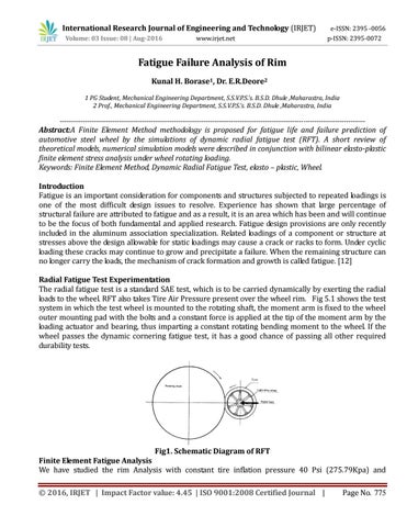
Abstract:A Finite Element Method methodology is proposed for fatigue life and failure prediction of automotive steel wheel by the simulations of dynamic radial fatigue test (RFT). A short review of theoretical models, numerical simulation models were described in conjunction with bilinear elasto-plastic finite element stress analysis under wheel rotating loading. Keywords: Finite Element Method, Dynamic Radial Fatigue Test, elasto – plastic, Wheel. Introduction Fatigue is an important consideration for components and structures subjected to repeated loadings is one of the most difficult design issues to resolve. Experience has shown that large percentage of structural failure are attributed to fatigue and as a result, it is an area which has been and will continue to be the focus of both fundamental and applied research. Fatigue design provisions are only recently included in the aluminum association specialization. Related loadings of a component or structure at stresses above the design allowable for static loadings may cause a crack or racks to form. Under cyclic loading these cracks may continue to grow and precipitate a failure. When the remaining structure can no longer carry the loads, the mechanism of crack formation and growth is called fatigue. [12] Radial Fatigue Test Experimentation The radial fatigue test is a standard SAE test, which is to be carried dynamically by exerting the radial loads to the wheel. RFT also takes Tire Air Pressure present over the wheel rim. Fig 5.1 shows the test system in which the test wheel is mounted to the rotating shaft, the moment arm is fixed to the wheel outer mounting pad with the bolts and a constant force is applied at the tip of the moment arm by the loading actuator and bearing, thus imparting a constant rotating bending moment to the wheel. If the wheel passes the dynamic cornering fatigue test, it has a good chance of passing all other required durability tests.
Fig1. Schematic Diagram of RFT
Finite Element Fatigue Analysis We have studied the rim Analysis with constant tire inflation pressure 40 Psi (275.79Kpa) and © 2016, IRJET | Impact Factor value: 4.45 | ISO 9001:2008 Certified Journal |
Page No. 775