
International Research Journal of Engineering and Technology (IRJET) e-ISSN: 2395-0056
Volume: 12 Issue: 05 | May 2025 www.irjet.net p-ISSN: 2395-0072
International Research Journal of Engineering and Technology (IRJET) e-ISSN: 2395-0056
Volume: 12 Issue: 05 | May 2025 www.irjet.net p-ISSN: 2395-0072
Pratik Chavan1 , Omkar Chowdhary2 , Pratham Vaity3 , Rohit Kamble4, Anuj Mandlik5
1Student, Department of Mechanical Engineering, Terna Engineering College, Navi Mumbai, India
2Student, Department of Mechanical Engineering, Terna Engineering College, Navi Mumbai, India
3Student, Department of Mechanical Engineering, Terna Engineering College, Navi Mumbai, India
4Student, Department of Mechanical Engineering, Terna Engineering College, Navi Mumbai, India
5Student, Department of Mechanical Engineering, Terna Engineering College, Navi Mumbai, India ***
Abstract – Thepaperoutlinesthedesignmethodologyand development process of a double wishbone suspension intendedforaFormulaStudentEV.Thesystemwastunedfor handling, durability, and compliance with competition standards. CAD modeling, kinematic analysis, and FEA were conducted to ensure geometry and strength validation. To optimize packaging constraints and enable finer suspension tuning, a bell-crank layout actuated via pushrods was integrated into the system. Load cases were examined to ascertain reliability under race conditions. The ultimate system was constructed and tested, showing satisfactory performance and structural integrity.
Key Words: Suspension System, Double Wishbone Suspension, Finite Element Analysis (FEA), Vehicle Dynamics, Vehicle Performance, Suspension Optimization.
Ineveryautomobile,thesuspensionsystemfunctionsasa fundamental element establishing the mechanical connectionbetweenthechassisandthewheels.Moreover,it operates as the backbone element in vehicle dynamics by regulating wheel trajectories and maintaining optimal camber throughout dynamic manoeuvres by transferring shocks and impacts of tires and evenly distributing them throughoutthemainframe.Thisisverycriticalintherealm of elite motorsport systems like Formula One, Formula Endurance,etc.Also,theFormulaStudentracecars,which areessentiallyscaled-downreplicasofFormulaOnecars,are designedandbuiltbyuniversitystudentsforcompetitions such as Formula Imperial and Supra SAE. Evolving suspension design holds elevated significance, offering effortless adjustability, mass efficiency, and razor-sharp controloverwheeltrajectory[1].Performanceautomobiles frequently employ the double wishbone suspension setup that provides better performance. Double wishbone can have two different options: push-rod or pull-rod actuated systems;eitherofthemmaybeimplementeddependingon theneedsandobjectivesofthevehicle.Somecomponentsof suspension structural units are springs, tires, dampers, shockabsorbers,A-controlarms,andwheeluprights.They work in conjunction with the vehicle frame to control the forces exerted by the road uncertainties. Also, in
motorsports,thissystembecomesimportantasitsetsthe frameworkforthevehicle'sbehaviourinturningandgoing over the curbs. A perfect suspension setup enhances a vehicle'son-trackperformance
Earlier, car suspension systems came from simple designsusedincartspulledbyoxen.Backthen,theyused ironchainsandlaterleatherstrapstohelpsoftentheride. Whencarsstartedmovingontheirown,newmetalworking techniques were needed. This led to better spring suspensionsthatmaderidessmoother.Inthe19thcentury, ObadiahElliottpatentedsomethingreallyimportant:strong steelleafspringsthatcouldholdupvehiclebodiesrighton the axles [2]. By 1904, we saw the first signs of what we know today as modern car suspensions. Then, in 1906, thingsgotevenbetterwiththeadditionoffrontcoilsprings onflexibleaxles.Leafhasalonghistory,datingbacktotheir use in carriages around 1804. People liked them because they were cheap and could handle different loads by changingtheirshape.Andeventhoughcoilspringswerefirst thoughtofwaybackin1763,carmakerschoseleafsprings forhowpractical&versatiletheywereinthoseearlyvehicle designs.
Adetailedsimulationstrategywasemployedtodetermine precisehardpointlocations,optimizingsuspensiongeometry forresponsivevehicledynamics[3].Follow-upvalidations ensuredthattheconfigurationbalancedstructuralpackaging with performance objectives. Suspension geometry modificationswereimplementedtoensurevehiclebalance during transient manoeuvres like turning, braking, and accelerating [4]. Accuracyin caster-camber alignmentresultedincorrelatedlateral force behavior andenhancedtrajectoryconsistencyduringmaneuvers.Ontrack feedback reported substantial improvements in responsiveness and stability. A sequential process was employed to incorporate push-rod actuation in the front suspensionsothatitiscompatiblewithA-armlocationand spring-damper orientation [5]. The layoutminimizedpackagingandfacilitatedcontrolledforce
International Research Journal of Engineering and Technology (IRJET) e-ISSN: 2395-0056
Volume: 12 Issue: 05 | May 2025 www.irjet.net p-ISSN: 2395-0072
distribution. Suspension arm geometry was analysed intensively,payingparticularattentiontounequal lengths for ensuring favourable tire contact during cornering [6]. Thiscontrolarmconfigurationservedtominimizebodyroll and enhance cornering confidence. Test performance indicated consistent behaviour under changing grip conditions. A light yet rigid design was sought through meticulous fabrication decisions, prioritizing stiffness balancing with mass reduction for the best dynamic response [7]. Progressive development allowed the customization of structural components without compromisingreliability.Fieldtestingshowedconsistency across diverse racing conditions. Suspension kinematics were studied to ensure wheel alignment and force distributionunderactualloads[8].Thefinaldesignreacted as expected to irregular surfaces. Regulatory limitations werefollowedduringthedesign,particularlywithregardto geometry and ground clearance, as per Formula Bharat regulations[9].Thesystem wasoptimized withinallowed limitstoimproveridequality.Therulecomplianceensured competitiveparticipationwithoutsacrificingfunctionality. Compact, dependable suspension geometry was created, utilizing virtual models to minimize high-stress areas and improve endurance under prolonged loads [10]. Finite element outcomes informed crucial strengthening. The system-maintainedperformanceacrossseveralracecycles without deterioration. A systematic design philosophy consistent with competition goals prioritized manufacturability,rulecompliance,andeffectivesimulation cycles[11].Designiterationsweremotivatedbyanalytical understandingaswellasassemblypracticability.Motionand vibration behaviour were studied to confirm suspension capabilityofwithstandinghigh-stressracingenvironments withoutmeasurabledegradation[12].Analyticalfrequencies correlated with test feedback. The system remained mechanicallyrobustunderrace-levelexcitationconditions.
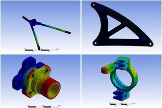
Thisresearchtakesacarefullookathowtocreateabetter suspension system for an electric vehicle in the Formula Studentcompetition.Itallstartswithathoroughreviewof important books, like Carroll Smith’s "Tune to Win" & Milliken & Milliken’s "Race Car Vehicle Dynamics." From there,wefigureoutthemaindesignideasusingtheories& handcalculations[13],[14].Next,wemakedetailed3DCAD models. We use software like SolidWorks for this, so everything is super precise and ready for making. Then comesastepwherewecheckthestrengthofourdesigns.We useFiniteElementAnalysis(FEA)inANSYStocheckfailures, motion dynamics, and various load and stress conditions. Then the next step was fabrication, which involves laser cutting,grinding,welding,plusassemblingeverythingusing bolts & press-fitting methods, also integrating it with the chassis, which in conjunction made over vehicle stand on wheels.Oncethiswasachieved,wetestedithardtoseehow welltheyperformindifferentsituations.Allourfindingsare
documentedcarefullybecausethey’remeantforrecording our data, which can be further used for perfect tuning of suspension parts, dampers, and various wheel angles to extract peak performance of the vehicle in competition, sharingwithothersinacademia,andmightevenbeusedin FormulaStudentcompetitions.
Thedesignofavehicle’ssuspensionsystemdirectlyaffects itsdynamicperformancecharacteristics.Thehandlingand performanceofaformulavehicleareprimarilyimpactedby suspension. To achieve the vehicle's full potential, it is necessary to get the suspension setup correct. Even small changesinsetupcanmakethevehiclesloweror evencan makeadrasticchangeinhandling.Thesuspensionsystem also ensures vehicle performance in a straight line and in cornering.Thereisaproceduretogetthesuspensionsetup perfectlysuitableforthetrackandtogetthevehicletoits fullpotential.Firstly,wedecidedonthebasicparametersof theFSAEvehiclelikewheelbase,trackwidthfrontandrear, and ground clearance. The tire sizes, parameters, and profiles are crucial to consider. The actual design of suspensionrequiresmanyparameterstobeassumed,like scrub radius, toe camber, caster angles, and kingpin axis inclination. For a design of suspension without load, it is feasibletotakethetoeangletozeroandthecambertobe positive.Plottingtheseanglesandparametersonpaperand onSolidWorksdesigningsoftwarewitha2Dcross-section diagramofthechassiswherethetireslie,andjoiningthem asshowninthefigureshownbelow.Thisgaveafrontview ofhowwishboneslie.Thesamestepswerefollowedforthe rear tire. Now for side points of wishbones, assuming an anti-diveandanti-squat percentage[15]. TakingtheSVSA lengthandjoiningitwiththeCentreofgravity,wegotthe pointswherethewishboneslieonthechassis.Thisdesign successfully gives a location for wishbone points on the chassis, which will help the car to balance out every situation, like bumps, turning, braking, etc. Once the wishbonepointsarecompleted,calculatetheweightoneach tirebytheweightratioofthecar,andthencalculatethesafe dimension for pushrods and wishbone rods. Performed various simulations and verified our design on the Ansys Workbench. Then, to make the suspension soft or hard, responsive or stiff, depending on weight, bell cranks are used. A structural approach was taken to integrate a bell crank to improve the suspension stiffness and which maintainsthegroundclearance.Thisisthedesignprocedure wefollowedandmadeasuccessfulsuspensionsystemthat gets the vehicle to its limits and helps us achieve a competitiveedgeincompetition[16]
Listedbelowarethemeaningsofimportantparametersthat areessentialtodesigningasuccessfulsuspensionsystem.
Scrub Radius:Itisaquantifiedvalueinthelateraldirection fromthecentrepointoftheinteractedareaofthetiretothe steering axis ground intercept point. An optimally tuned
International Research Journal of Engineering and Technology (IRJET) e-ISSN: 2395-0056
Volume: 12 Issue: 05 | May 2025 www.irjet.net p-ISSN: 2395-0072
scrubradiushelpstoenhancesteeringaccuracyandtactile driverfeedback.
Toe-in and Toe-out: Wheel angular inclination about the verticalplane,affectingtiredegradationandstability.Toe-in means the tires tilt inwards, while toe-out means tilt outwardsalongtheverticalaxis.
Caster Angle: Refers to the degree of inclination of the upright axis from vertical, affecting steering effort and stability. Positive caster is used in conditions where cornering is not a concern, and negative caster is used to optimize cornering performance, apart from straight line speed.
Camber Angle: Refers to the inclination of the wheel inwards or outwards, influencing tire wear and cornering grip. Positive camber improves manoeuvrability, while negativecamberaffectsthesame
Roll Centre: It is the fulcrum around which the car body swingsthroughcornering.Ithasastrongeffectonchassis rollresponse,directionalstability,anddynamicresponseto steeringinput
FVSA and SVSA:Swingarmlengthsviewedfromthefront (FVSA)andside(SVSA),affectingdynamicbehaviourslike anti-diveandanti-squatcharacteristics.
Wheel Travel: The distance travelled by any point of the wheelintheverticaldirectionfromitsrestingposition.
5.CALCULATIONS
Abbreviation
Tr=TrackWidth(Rear)
Tf=TrackWidth(Front)
L=WheelBase
W=weight
F=force
Wf=WeightoffrontWheelwhenrearelevated
r=Tireradius
MR=MotionRatio
Fp=Forceonpushrod
BMR=Bellcrankmotionratio
Ks=springrate
Fr=Ridefrequency
Msm=Sprungmass
Kw=Wheelrate
kwFL=wheelratefrontleft
kwFR=wheelratefrontright
KψF=Frontrollrate
KψR=Rearrollrate
CalculationoftheC.G.Height
WecalculatetheCentreofgravity(C.G.)insuspensiondesign because it directly affects how the vehicle handles forces during acceleration, braking, and cornering, like Weight Transfer,SuspensionGeometryTuning,andVehicleBalance
W(withoutdriver)=270Kg
W(Driver)=70kg
W(Total)=270+70=340Kg
‘Assuming60:40’
Weightdistribution:
W(Front)=136Kg
W(Rear)=204Kg
W(eachrearwheel)=102kg
W(eachfrontwheel)=68kg
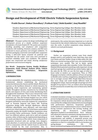
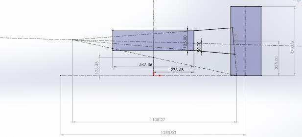
L=1620mm
Tf=1250mm;Tr=1300mm
CenterofGravity=
FromRear=b=567mm
FromFront=a=1053mm
International Research Journal of Engineering and Technology (IRJET) e-ISSN: 2395-0056
Volume: 12 Issue: 05 | May 2025 www.irjet.net p-ISSN: 2395-0072
W (rear) > W (front) as the battery is fitted near the rear axle.
Now,amomentaboutxx
y′=W2/W(T−d)−W1/W(d)=W4.TR/W
y’=640mm
y’’=0.64-(1.3/2)
y’’=0
Since there is no horizontal offset in the X direction, the lateralshiftisdeemednegligible.
LoadCalculations
LongitudinalForcesduringBraking:
Asthecarbrakes,massistransferredforward,puttingmore load on the front suspension. That increased force passes through the A-arms and is imparted to the knuckle where theyareattached,influencingthesuspensioncomponents' responsetobraking.
AssumeMaxacceleration=9.81m/s2
F(frontside)=M(rearside)×acceleration
LettheM(rearside)=0.6timesthetotalweight
M(rearside)=0.6×340=204kgF=204×9.81F=2001.24N
NowF(onewheel)=2001.24/2=1000.62N
F(Longitudinal)=1000.62N
LateralForces
F(Lateral)actedduetotworeasons:F(centrifugal)andload transfer (lateral from outer to inner while cornering). The computationofcentrifugalforce:
Take,speed(vehicle)=30kmph=8.33m/sandr(Turning radius)=6m
Now,considerifW(total)actsonthefrontwheelassembly,F (lateralloadtransfer)=0.4×340×9.81=1334.15N
VerticalForceatBump
Atthebump,loadtransfer(vertical)=3goftheWeightofthe vehicle.
Load transfer (vertical) on each wheel (Front)=667x3 =2001.24N
Loadtransfer(vertical)oneachwheel(Rear)=1000.62x3= 3001.86N
SuspensionCalculations
FrontSuspension
MotionRatio[MR]=WT(wheeltravel)/ST(springtravel)
MR[front]jounce=25/19.13=1.306
MR[front]rebound=25/20=1.25
MR[front]=(1.3068+1.25)/2=1.278
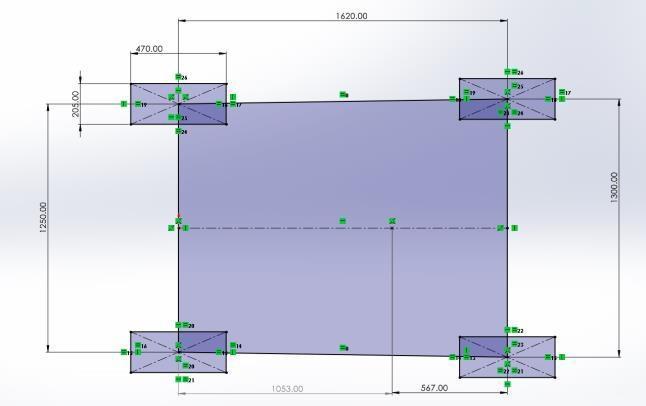
F(frontsinglewheel)=667.08N.
F(singlefrontwheelatbump)=2001.24N.
α=20.20,β=77.36:
Therefore,FP=2001.24cosα=2001.24cos(20.20)
Fp=1878.14N
1km/hr.=1000/3600m/sec,=5/18m/sec
Centrifugalforce=(m*e2)/r=(0.4*340*8.333)/6=1573.94N
Now,
AssumeFr(ridefrequency)=1.68Hz
KS=4xπ2 xFr2 xMsmxMR2 [17]
Ks(Front)=4xπ2 x(1.68)2 x135x(1.278)2
Ks=24832.60N/m
Therefore,selectingthestiffness(front)=24900N/mor24.9 N/mm
Kw[Front]=(Ks)/MR2 =24.9/(1.278)2
Kw[front]=15.25N/mm
Kw[front]=kwFL(left)=kwFR(right)
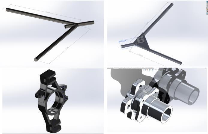
Figure -3:Frontsuspension
Also,
KψF=πx(Tf)2 x(kwFLxkwFR)/180(kwFL+kwFR)[17]
KψF=π(1.25)2x15250x15250/180x(15250+15250)
KψF=207.93Nm/deg
RearSuspension
MR[rear]jounce=25/19.13=1.3068
MR[rear]rebound=25/20=1.25
MR[rear]=(1.3068+1.25)/2=1.278
International Research Journal of Engineering and Technology (IRJET) e-ISSN: 2395-0056
Volume: 12 Issue: 05 | May 2025 www.irjet.net p-ISSN: 2395-0072
SinceMR(front)=MR(rear), Therefore,KW(FR&RR)andWT(FR&RR)arethesame Forceonrearsinglewheel=1000.62N. Forceoneachrearwheelatbump=3001.86N.
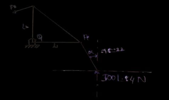
α=18.22:β=90
Therefore,FP=3001.84cosα=3001.84cos(18.22)
FP=2851.33N
FS=FPxBMR=2851.33x1
FS=2851.33N
AssumeRr(ridefrequency)=1.68Hz
Fr=1.68Hz
Ks=4xπ2 xFr2 xMsmxMR2 [17]
Ks(Rear)=4xπ2 x(1.68)2 x135x(1.278)2
Ks=24832.60N/m
Therefore,Ks[Rear]=24.9N/mm.
SinceKs(Front)=Ks(Rear), Therefore,Kw(front)=Kw(Rear).
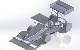
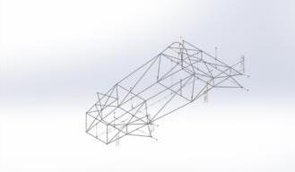
6. CAD MODEL AND DESIGN ANALYSIS
7. FARICATION
The design procedure for the suspension system is completed with a very careful approach. CAD models &
International Research Journal of Engineering and Technology (IRJET) e-ISSN: 2395-0056
Volume: 12 Issue: 05 | May 2025 www.irjet.net p-ISSN: 2395-0072
analysis results were strictly executed, and only safe parameters were taken into consideration. This is super importanttogeteverythingjustrightforperformance.We usegreatCNCmachining&othertechniquestocreateparts exactlyasweneedthem.CADsimulationshelpuschoosethe rightmaterials.Sometimes,wefacesmallchallengesduring manufacturing.So,wemakelittlechanges,likeadjustingthe screw threading for eyeball joints, pushrods, & tie rods. Thesetweakshelpusfine-tunethingsliketoe-inandtoe-out, casterangle,camberangle,andscrubradius.Becauseofthis, our final prototype really meets all the performance and reliabilitystandardsneededforautomotiveuse.
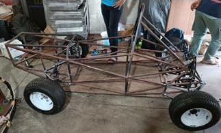
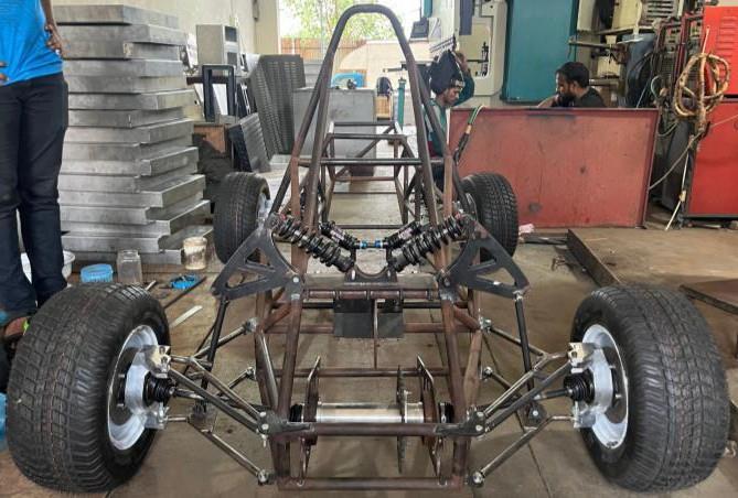
Table -2: EquivalentStress(StaticStructuralAnalysis)
Weputalotofcareintodesigning,analyzing,&makingour suspensionsystem.Everylittledetailwasimportanttous. Wefocusedongettingthebestperformance,makingitlast long, & keeping costs down. Using fancy Computer-Aided Design(CAD)toolsandsimulations,webuiltthesuspension systemaccordingtocompetitionrulesandregulations,such asjounceandre-jounceof±25mm,andgroundclearanceof 30mm,compactindesign.Weusedfiniteelementanalysis (FEA)todouble-checkthatourdesignwouldbestrong,safe, andreliable.StickingcloselytowhatwesetoutintheCAD models helped us keep things consistent during manufacturing. Quality was key during this phase. This Improvedmaneuverability,comfort,&overallsportinessof thevehicle.Thankstooursmartapproach,wemanagedto keep prices competitive without skimping on quality or performance.Wemadesureeverythingwentthroughtough qualitycheckssothefinalproductwouldmeetallourgoals. Inconclusion,allourhardworkindesign,analysis,&making hasledtoafantasticsuspensionsystemthat'sjustrightfor theFSAEVehicle.Bymixinghigh-techtoolswithsmartcost choicesandcarefulqualitychecks,we'vecreatedsomething great. For teams new to FSAE, focusing too much on complicatedengineeringstuffcanendupwastingtimefor onlyabitofperformanceimprovement.So,forFSAEteams, itisbettertoalwaysstartfrombasicengineeringprinciples and develop specific components of their vehicle. This approachmakeseverythingsimplerandhelpsthemfinish sooner,allowingmoretimefortestingandmakingchangesif needed. Teams that finish their cars & get to compete are likely to learn the most and get valuable experience from FormulaSAE.
International Research Journal of Engineering and Technology (IRJET) e-ISSN: 2395-0056
Volume: 12 Issue: 05 | May 2025 www.irjet.net p-ISSN: 2395-0072
[1] Singh, A., Verma, S. K., & Maurya, P. K. (2019). FEA of automobilesuspensionsystemforvibrationelimination. IJARIIT
[2] Sathishkumar, K., & Dinesh, G. (2019). Design and Material Analysis of a Suspension System in Scooter. IRJMT
[3] Wagh,S.Y.,&Nandi,E.A.(2019,September).Designand AnalyticalCalculationsofDoubleWishboneforFormula Student Race Car. International Journal of Mechanical andProductionEngineering(IJMPE).
[4] Anirudh,K.,Sriram,K.,Jayanth,B.,&Anjaneyulu.(2021, August).EnhancingPerformancewithDoubleWishbone Suspension. International Journal of Automotive EngineeringandTechnologies
[5] Jain,K.K.,Behera,S.K.,&Gandhi,D.(2015,December). Design Procedure of Front Double A-Arm Push Rod Suspension.12thInternationalConferenceonVibration Problems(ICOVP).
[6] Sabino,U.,Wirawan,J.W.,&Alnursyah,R.(n.d.).Design Analysis of Unequal Double Wishbone Suspension. International Journal of Mechanical and Production Engineering(IJMPE).
[7] Bhatia,K.(2021,December).ComprehensiveStudyon Suspension System Design. International Journal of EngineeringResearch&Technology(IJERT).
[8] Prince, S. P. (2014, July). Importance of Suspension System in FSAE Vehicles. International Journal of Innovative Research in Science, Engineering and Technology(IJIRSET).
[9] Ahmad, A., Hassaan, M., Nayeem, F., & Alam, M. (n.d.). Efficient Suspension Design under Formula Bharat Guidelines.InternationalJournalofScientificResearch andEngineeringDevelopment(IJSRED).
[10] Vadhe, A. A. (2018, May). Compact and Reliable Suspension Design. International Journal of Current EngineeringandTechnology(IJCET).
[11] Levy,A.,&Potter,J.J.(2019,November).Rationaleand Design Constraints of WUFR-19 Suspension. FSAE MichiganTechnicalReportSeries
[12] Saurabh, S., Kumar, S., & Jain, K. K. (2015). Detailed DesignandAnalysisofFrontDoubleA-ArmSuspension. SAETechnicalPaperorConferenceProceedings
[13] Smith,C. (1978). Tune to Win:TheArtandScienceof Race Car Development and Tuning. Motorbooks International.
[14] Milliken,W.F.,&Milliken,D.L.(1995).RaceCarVehicle Dynamics.SAEInternational.
[15] Pacejka, H. B. (2005). Tire and Vehicle Dynamics. Elsevier
[16] Rajamani, R. (2011). Vehicle Dynamics and Control. Springer
[17] AshishAvinashVadhe(2018).DesignandOptimization of Formula SAE Suspension system. International JournalofCurrentEngineeringandTechnology.
[18] https://youtu.be/JDKgwjwIyT4?si=9hhlBt4y8828Wclf
[19] https://youtu.be/S_GraRRbxLg?si=Ai3TEzO7V3_v7Tf3