International Research Journal of Engineering and Technology (IRJET)
e-ISSN: 2395 -0056
Volume: 03 Issue: 03 | Mar-2016
p-ISSN: 2395-0072
www.irjet.net
THE POWER FACTOR CONTROLLER BY USING MICROCONTROLLER Sabiya T. Mujawar1 , Sonali S. Lad2 , Milan R. Patil3, P. U. Mohite4 1,2,3Student,
Dept.of E&TC, Sanjeevan college of Engineering Kolhapur,Maharashtra ,India (mujawarsabiya33@gmail.com1), (sonalilad1748@gmail.com2), (patilmilan1694@gmail.com3) 4Asst.prof., Dept.of E&TC, Sanjeevan college of Engineering Kolhapur,Maharashtra ,India ---------------------------------------------------------------------***---------------------------------------------------------------------
Abstract - This paper describe the power factor correction
In an ac circuit,the average power is generally given
of an inductive load by using capacitor bank. The power factor is the ratio of actual power and apparent power, hence it affects the power energy.If it is less than 1 then electricity company have to supply more current to the users. Low power factor is not usually that much of a problem in residential. However become a problem in industry where multiple large no.of motors are used. Generally ,the power factor is corrected by addition of capacitors in parallel with the inductive load.In this,the V and I waveforms are converted into square waveform by using ZCD and the output is supplied as input to the microcontroller at int0 and int1 and the difference between the arrival of waveforms is measured by using internal timer .This time value gives the phase angle and corresponding Power Factor.Depending upon the output from the MC the capacitors are switched by relay driver.
by,
Key Words: power factor , inductive load , simulation ,
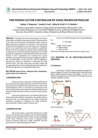
An inductor with AC supply and phasor diagram is shown in figure 3.1a and 3.1b respectively, which shows the phase angle between current and voltage . In case of an inductor voltage lead current by 900. The voltage across an inductor leads the current .
power factor correction etc.
1.INTRODUCTION
Where,
P = VIcos(Ø)
cos(Ø) - Power factor V - RMS Voltage I - RMS Current If the load is resistive then power factor is equal to one.
3.AC RESPONSE OF AN INDUCTOR,CAPACITOR ,RESISTOR 3.1 Inductor
The power factor is the ratio of KW and KVA driven by an elecrical load such as inductive load where the KW is the actual power and KVA is the apparent power. Due to the industrialisation, there is increased use of inductive load. Due to which power factor decreses so that the efficiency of overall system decreses so there is need to increse power factor. A low power factor due to an inductive load can be improved by the addition of capacitors in parallel with an inductive load . So ,in this paper we are using a method of automatic switching of capacitors by using automatic microcontroller ,which is used to reduce cost . Fig 3.1a) Inductor
2.POWER FACTOR The power factor is generally denoted by cos(Ø) term. In case of inductive load,the current waveform lags the voltage waveform and the power factor is said to be lagging power factor. Whereas if the circuit is capacitive then current waveform leads the voltage waveform and the power factor is called leading power factor.
Fig 3.1b) Phasor dia. of an inductor © 2016, IRJET
ISO 9001:2008 Certified Journal
Page 520