FUZZY LOGIC CONTROLLER BASED MPPT METHODS FOR THE MULTILEVEL INVERTERS TO THE ELECTRIC VEHICLES
Mr. B. Srikanth1 , Dr. Sivaganesan Sivanantham21PG student, Department of Electrical & Electronics Engineering, Holy Mary Institute of Technology & Science, Hyderabad-500043, India.

2Professor, Department of Electrical & Electronics Engineering, Holy Mary Institute of Technology & Science, Hyderabad-500043, India. ***
Abstract - TheeffectiveandconservativedesignofMulti level inverters (MLI) spurs different applications, for example,solarpoweredPVandelectricvehicles(EV).This paperproposesastaggeredinvertergeographyinlightofan exchangedcapacitor(SC)approach.Thequantityofdegrees ofMLIisplannedinlightofthefountainassociationofthe quantity of SC cells. The proposed structure is direct and simple to carry out for the more significant levels. As the quantityofdynamicswitchesisless,thedrivercircuitsare diminished.Thislessensthegadgetcount,cost,andsizeof the MLI. This paper presents the plan and displaying of a fluffyregulatorforfollowingthegreatestpowerpointofaPV Framework.PVmodule,buckconverterandfluffyregulator; featuringasprincipalcuriositytheutilizationofanumerical modelforthePVmodule,which,notatalllikediodebased models, just has to work out the bend fitting boundary. A P&O regulator to contrast the outcomes got and the fluffy controlwasplanned.Thereenactmentresultsexhibitedthe predominance of the fluffy regulator concerning settling time,powermisfortuneandmotionsattheworkingpoint. Near examination of the decreased switch inverter geographies in view of the part count, all out consonant twistingofresultvoltage,andeffectivenessisadditionally introduced in this paper. The sunlight powered chargers, alongsideaMoleculeswarmEnhancement(PSO)calculation, giveasteadyDCvoltageandishelpedovertheDCconnect voltage utilizing a solitary info and multi-yield converter (SIMO). A Recreation model is carried out and confirmed tentatively under powerful burden varieties, though the reenactmentsarefinishedinMATLAB/Simulink.
Key Words: multilevelinverters(MLI),solarPVandelectric vehicles (EV), switched capacitor (SC) maximum power point,fuzzy,singleinputandmulti-outputconverter(SIMO)
1. INTRODUCTION
Withtheinterestforanexpansioninthenecessitiesofhighpower quality in modern applications and sun based PV Systems, the traditional inverters in gathering the ideal circumstanceslikeanunadulteratedsine-waveyieldandless consonant contortions is a difficult errand. The staggered inverters get more consideration in arriving at the ideal prerequisites and goes about as an option in conveying a nature of force. It gives a few benefits, for example,
decreased gadget count, works in low exchanging recurrence,diminisheddv/dtstress,lessconsonanttwists, and so on [1]. The new staggered inverter geographies containfewerpartsutilizedinthecircuitcontrastedandthe ordinaryinverters,for example,flyingcapacitor type(FC) [2],flowedH-spantype(CHB)[3],andtheimpartialpoint clippedtype(NPC)[4].Thequantityofpartsinthecircuitis straightforwardlycorrespondingtothequantityoflevelsin MLI,whichinflatescostandcomplexdesign[5].Inboththe FC MLI and NPC MLI, the capacitor voltage adjusting is a difficultundertakingwithwhichthesearerestrictedtofivelevelandunfittoflow.
For a PV took care of inverter, in delivering a steady DC voltage, there is a requirement for a control procedure. A standardPIregulatoracknowledgedintheindependentPV frameworktochoosealegitimateobligationpatternofthe DC converter by contrasting the converter result and reference[6].Itisn'talluringtohavecommandovertheDC converter with the MPPT strategy, and thus different geographies are proposed to tackle this issue for the independent planetary group. In the new past, a few high levelmethodslikecomputerizedreasoning(computerbased intelligence),functionalmultitudeenhancement(PSO),fluffy andhereditarycalculation(GA)tohaveanauto-controlwith respect to the preparation information to manage voltage [7].ThedeterminationoftheMPPTstrategyforareasonable applicationisashockingundertakingwhereeachtechnique hasitsownbenefitsandfaults.Forinstance,slopeclimbing (HC), bother, and noticing (P&O) and are broadly utilized MPPT techniques on account of their straightforward execution. Under fractional concealing circumstances, the regular strategies like fluffy, P&O, INC calculations can't remove worldwide MPP (GMPP) [8 Both sun oriented irradiance and temperature change during day time for climatic circumstances and contingent upon the season. Thus,itisimperativetofollowthismultitudeofboundaries andgetgreatestpowerpoint.
Inthispaper,asunbasedPVframeworkisexecutedutilizing a17levelstaggeredinvertercoordinatedwithasolitaryinfo, anddifferentresultDCsupportconverterisintroduced.P&O controlled MPPT procedure is executed in the proposed framework to separate pinnacle energy from the sunlight poweredchargers.DCvoltagefromthebetweenthesunlight
powered chargers took care of to the single info and different result support converter where the voltage gets helpedtotheideallevelandgiventothe17-levelinverter. TheSCunitsareflowedtoaccomplish 17degreeofresult voltages.ExecutionoftheseMLIsinviewofnumeroussuch boundaries like gadget count, power misfortunes, proficiency,THDiscontrastedanddifferentMLIgeographies and addressed. The carried out framework is tried in MATLAB/Simulink, though it is tried tentatively with an equipmentarrangement.
Closestlevelcontrol(NLC)tweakisutilizedfortheinverter control. As the HFL is bidirectional, the inverter shows magnificentexecutionduringregenerativeslowingdownof theEV.Theswitchesoftheprincipalconverterworkatthe essential recurrence, and subsequently, the exchanging misfortunesaresignificantlydiminished.Itisappropriatefor medium-and hard core EV applications. Ounejjar et al.30 presented a stuffed U cells seven-level inverter that consolidatedthebenefitsofFCMLIandCHBMLI.Asolitary stagePUCMLIcontainssixswitches,oneDCsource,andone capacitor. Figure 5 portrays the circuit chart of a solitary stagePUCMLI.Theresultvoltagehadsevenlevelswithyield voltagecontortionof25.23%andaresultcurrenttwistingof
4.96%. This geography is just liked for low-power applications and isn't reasonable for high-power applicationswherea high-voltageyieldisgotten withlow informationDC voltage. Besides,asthe capacitorhasonly one charging way, the DC-connect voltage doesn't stay steadywhenthecapacitorisreleasedforquiteawhile.This isthefundamentalrestrictionofPUCMLI.Theexchanging example of a seven-level PUC MLI. It is reasonable for medium-anduncompromisingEVapplications.
2. MODELLING OF PV AND DC-DC BOOST CONVERTER

2.1 MODELLING OF SOLAR PV

The modeling of a solar cell is an important segment of analyzing a solar PV system. The overall proposed circuit comprisessolarpanels,athree-levelDC-DCboostconverter fedto17-levelMLIshowninFigure1.ThesolarPVcanbe modeledwiththreecategoriessuchasanequivalentcircuit with current-voltage (I-V) and power-voltage (P-V) characteristics, the effect of solar irradiance and temperature,andthepartialshadingconditionistakeninto consideration.
PVresemblestwowordsphotoandvoltaic:photorepresents the photonic energy and voltaic represents the electrical energy, which implies that the energy conversion from photonic energy into electrical energy [1]. The designed solar PV has a behavior of changing its output with the variationoftemperatureandclimaticconditions[2].

2.2 SOLAR CELL: EQUIVALENT CIRCUIT AND I–V CHARACTERISTICS
The solar cell comprises internal resistance RSE and RSH connectedtothediodeinseriesandparallelcombination, knowntobeanequivalentcircuitshowninFIGURE2.VPV and IPV are the output voltage and current of a solar cell, respectively. These are got from the series and parallel connectionofseveralPVmodulesshowninequation(1), (1)
whereNSEandNSHarethenumberofPVcellsinseriesand parallelconnection.RSEistheseriesresistance,andRH is the parallel resistance. A is the ideality factor of a semiconductordevice.KisBoltzmann’sconstant(1.3806503 × 10⁻²³ J/K), T is ’he temperature. Ip is the current producedandisdependsontheirradiationandtemperature showninequation(2)


I-V/P-Vcurvesrepresentthecharacteristicsofasolarcellis shown in Figure 3 [4]. It is clear from the curve there is instability for the operating point of a PV; it varies continuously from null to open-circuit voltage. In this process,thereisasinglepointthatprovidespeakpowerfor the design of solar PV at various irradiance. Here, the respectivevoltageandcurrentsareVMPP,IMPPshownin Figure3.

The values of current and voltage got from the solar PV dependonirradiance,temperature, numberofseries,and parallel connected strings. So, it is required to choose the solarpanelwisely.Inthispaper,the1Soltech1STH-215-P panelischosenfromthelistofgivensolarmodulesdatain MATLABwith2seriesandparallelconnectedmodulesper string.Thespecificationsoftheselectedsolarpanelandthe readingsfor1parallelstringand1series-connectedmodule with a solar irradiance of 1000 W/m2 and 250oC temperature.
2.3 IRRADIANCE AND TEMPERATURE EFFECT

The solar PV output continuously varies with variation in climaticchanges[9].Asthesolarirradianceconfidesonthe incidence angle of sun rays, this effect forces the I-V/P-V characteristicstochange.TheoutputcurrentIPVvarieswith thevariationofsunrayincidence,makingVPVconstantand VPValsoshiftsitsmagnitude,makingIPVconstant[9].Three factorsareinfluencingthevariationintemperatureofasolar PV:Theheatdissipatedonitsownduringthefunctioningof PV,fortheinfraredwavelengthstarted,whichisawornon thecellandthegradualincreaseinthesunbeamintensity [6].TheVOCandISCaremeasuredbasedontheequations (5)and(6)atvariableirradiance.
(5) (6)
where ISK−STM is a short-circuited current at standard testingcases(STM),KiistheSCCcoefficient,G(W/m2)is theirradianceonthesurfaceofthecell,GSTM(1000W/m2) istheirradianceatSTM,andthecelltemperatureisTSTM [13].

Fromtheaboveequations,thetemperaturecoefficientsare a1anda2ofthePVcell,respectively[5].V0OCandI0SC are the reference parameters at solar intensity G’ and temperatureT0.Asthevariationsofclimaticconditionsare specific, it affects the output voltage and currents. At any point during the operation of solar PV, the maximum extractionofpowercanbedone.Thiscanbepossiblewith anefficientMPPTtechniquethattrackstheirradiationand temperatureandprovidesaconstantvoltageattheoutput.
3. DC-DC BOOST CONVERTER
whereVOK−STMisanopen-circuitedvoltageatthestandard testing case, KOV represents the open-circuit voltage coefficient,VSthissolarcellthermalvoltage.
A single input multiple output DC-DC boost converter interfaced in between the solar panels and the proposed
inverter is shown in Figure 1 [8]. This converter provides three isolated dc sources in the ratio of 4:1:3:9. The converterfeedsonasinglesolarPVtoeliminatetheunequal voltagesalongwiththevariationsinthestepsizebasedon severalclimaticconditions.


Themagnitudeoftheinductancecanbecalculatedusingthe relation:
(7)
whereVdcistheinputdcvoltage,misthemodulationindex, andfsistheswitchingfrequency,Iristheripplecurrent,ais the overloading factor which is usually 1.25. The value of capacitancecanbecalculatedusingtherelation


(8)
whereIdcisthedccurrent,fsistheswitchingfrequency,ris theripplevoltage,Vdcistheinputdcvoltage,Distheduty cycle.

Thedutycycleoftheconvertercanbecalculatedusingthe followingrelation:
(9)
Thesimulationandexperimentalresultsareshowninfigure 4andfigure5,respectively.Thespecificationsoftheboost converterarerepresentedrequirement,andtheupperlimits of the additional ripple voltage. SC has the advantage of increasing the voltage level with its structural design. In general,aDC-DCconverterisrequiredtogetaratedoutput fed to the inverter but irrespective of the converter rated output,intheproposedtopologyvoltagegetsboostedbased ontheSCdesigninitscharginganddischargingbehaviour. TheadditionofseveralSCunitsresultsintheproductionof thevarious numberof levelsofmultilevel inverters. Here, theSCunitsarecascadedtoform17MLI.

Figure4(a)&Figure5(a),underoptimalconditions,during eachhalf-cycle,thecapacitorCischargedthroughS2switch during V0 = ±Vc1. The discharging of the capacitor C is startedwhentheswitchS1isinconductionatthefrontend oftheproposedMLItopology.Duringthedischargingperiod, thediodeDandswitchS2getsturnedoff.V1andVC1supply energytotheloadandtherespectivemaximumloadcurrent isknownwhere
(10)
The discharging period can be used for obtaining the optimum value of SC for obtained ripple voltages. The simulationoutputwaveformshowninFigure5(b).
LetQCbethechargereleasedbyC1duringtheperiod,then (11) wheretd1,td2istheperiodofdischarging,I0ismaximum outputcurrent,fsisthefundamentalfrequency,andϕisthe phasedifferenceamongthevoltageandcurrent.1VCisthe ripple voltage and can be calculated using the angles computedusing (12)
whereθistheanglewherethecapacitordischargesandπθ istheanglewherethecapacitorisdischargingstops.

DesignandModellingofPVSystem
Figure1showsthegeneraldiagramofthePVsystem,which iscomposedofthe65WPVmodule,thebuckconverter,the batteryandtheMPPTalgorithm(fuzzyorP&O)
4. Fuzzy Controller
4.1 Membership Functions
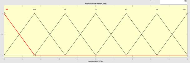
Triangular membership functions for the fuzzification processwereused.FortheinputsE,CEandfortheoutput ΔD, 5 membership functions were defined in terms of the following linguistic variables: Very Low (MB), Low (B), Neutral(N),High(A)andVeryHigh(MA).Therangeforthe erroris(−60to100),forthechangeoferroris(−10to10) andfortheincrementindutycycleis(−0.01to0.01).Figure 7 shows the membership functions for the inputs and outputsofthecontrollers.

4.2 Fuzzy Controller Modelling
The controller was modelled with the Matlab Fuzzy Logic Toolbox (Math Works, Natick, MA, USA). A Mamdani controller with the centroid defuzzification method was used. This procedure was carried out using the fuzzy inference system editor (FIS editor) (Math Works, Natick, MA, USA). Figure 9 shows the controller modeled in Simulink,forwhichasubsystemwasperformedtocalculate ∆Vand∆PinordertoobtaintheinputsEand∆E.
fuzzy/P&Ocontroller.Thesignalbuilderblockwasusedto generatethetemperatureandirradiancesignalsinorderto evaluate the controller performance. Additionally, this system was used to evaluate the standard P&O controller andperformthecomparisonwiththefuzzycontroller.
4.4 Limitations
Thedc-dcconverterandfuzzycontrolweredesignedbased ontheelectricalparametersofthePVmoduleunderstudy; forthisreason,thecalculationsmadeapplytoPVmodules with powers up to 65 W. One of the inputs of the fuzzy controller is the change of error, which requires a differentiationoperationthatincreasesthecomplexityinthe calculationsandcangenerateerrorswhenmeasuringsmall powersthataresensitivetonoise.
5. Simulation Results
17-LEVEL MLI
A17-levelMLIisdesignedwiththetwoSCunitsconnected incascadewithasmallernumberofcomponentsisshownin FIGURE 9. The proposed MLI topology comprises 10 controlledswitcheswithtwoasymmetricDCsourceswith theabsenceofinductors.
4.3 PV System Modelling


ThePVsystemimplementedinMatlab/Simulink, whichis composed of the PV module, the buck converter and the
ThetwoDCsourcesareofunequalvoltagelevelsformedto be an asymmetrical configuration. Several power quality issuesliketotalstandingvoltage(TSV),costfactor,andcost per unit with various values of the weight factor, THD, switch count, component count level, voltage stress is minimized with this MLI topology. This topology achieves lessTSVandiscomparedwithvarioustopologies.Thepath oftheloadcurrentthroughtheswitches.

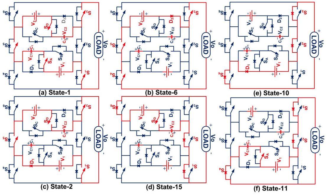
Thedeveloped17-levelMLIisoperatedinvariousmodesof operation.Inmode-1operationofthecircuit,theswitches

SA,S5,SD,S3,S1turnonformingaloadcurrentpath,where V1,VC1,V2,andVC2sourcesactinthecircuitandproducea voltage of 50V, 150V, 50V, 150V respectively to get a maximum voltage of 400V. In mode-4 operation, the switchesSA,S5,D2,S3,S1turnonwiththevoltagesV1,VC1, and V2 sources act in the circuit and produce a voltage of 50V,150V,and50Vrespectivelyandgetavoltageof5Vdc whichisequalto250V.Inmode5operation,theswitchesD1, S5,D2,S3,S1turnonwiththevoltagesV1andV2sources act in the circuit and produces a voltage of 50V and 150V respectively and get a voltage of 4Vdc equal to 200V. In mode-6operation,theswitchesD2,S3,S4,S5,turnonwith

thevoltageV2sourceactinthecircuitandproduceavoltage of50Vandgetavoltageof3Vdcwhichisequalto150V.In mode-7operation,theswitchesSA,S5,S6,S1,turnonwith the voltages V1 andVC1 sources act in the circuit and producesavoltageof50Vand150Vrespectivelyandgeta voltageof2Vdcequalto100V.
Inmode-8operation,theswitchesD1,S5,S6,S1turnonwith the voltages V1 source act in the circuit and produces a voltageof50VrespectivelyandgetavoltageofVdcwhichis equalto50V.
Inmode-9operation,theswitchesS1,S2,S3,turnonwithno voltages acts in the circuit and produces a voltage of 0V. Hence the positive cycle is created. The negative cycle is implemented with the negative modesof operation, along withtheswitchingstates.
The output waveform for output voltage and currents are showninfigure14,andfigure15.Theexperimentaloutput voltageandoutputcurrentarerepresentedinFIGURE16. TheMLIistestedwithR-load,andtheobtainedvoltageand currentsare400Vand4A.
17-LEVEL MLI

A17-levelMLIisdesignedwiththetwoSCunitsconnected incascadewithasmallernumberofcomponentsisshownin FIGURE 9. The proposed MLI topology comprises 10 controlledswitcheswithtwoasymmetricDCsourceswith theFIGURE9.Developedstructureof17-levelMLI.Absence of inductors. The two DC sources are of unequal voltage
levelsformedtobeanasymmetricalconfiguration.Several powerqualityissuesliketotalstandingvoltage(TSV),cost factor,andcostperunitwithvariousvaluesoftheweight factor, THD, switch count, component count level, voltage stress is minimized with this MLI topology. In mode-1 operationofthecircuit,theswitchesSA,S5,SD,S3,S1turn onformingaloadcurrentpath,whereV1,VC1,V2,andVC2 sources act in the circuit and produce a voltage of 0respectivelytogetamaximumvoltageof80V.Inmode-2 operation,theswitchesD1,S5,SD,S3,S1turnonwhereV1, V2,andVC2sourcesactinthecircuitandproduceavoltage of80Vrespectivelyandgetavoltageof8Vdcwhichisequal to80V.Inmode-3operation,theswitchesSD,S3,S6,S5turn onformingaloadcurrentpathwhereV2,VC2sourcesactin the circuit and produce a voltage respectively and get a voltageof5Vdcequalto80V.


CONCLUSION
The proposed switched-capacitor based 17-level MLI topology for electric vehicle applications is designed and implemented for the solar PV energy system with lesser semiconductor devices to reduce the cost and size of the inverter, improving efficiency and reliability. Fuzzy based MPPTtechniqueisused,thestableoutputisachievedunder all circumstances.TheproposedMLIisimplemented with variouscombinationsofSCconnections.Abasictwounits arecascadedandobtaineda17-levelMLIconfiguration.All theMLIsaredesignedandcomparedwithvarioustopologies basedonseveralparameterslikedeviceslevelcount.Itwas demonstrated that the fuzzy controller has an excellent performance when there are sudden changes in the operating temperature of the PV module, in contrast with P&Ocontrolthatisconsiderablyaffected,presentingpower losses Inthisway,themaincontributionofthismanuscript istheguaranteeofsupplyingthemaximumpossiblepower toabatteryinanoff-gridPVsystem,usingafuzzycontroller. Asfuturework,inthesecondstageoftheproject,thefuzzy controllerwillbeimplementedTheproposedMLIistested under multiple dynamic load variations. This topology is most suited for renewable energy applications along with theEVapplications.
REFERENCES
[1]J.Rodriguez,J.-S.Lai,andF.Z.Peng,‘‘Multilevelinverters: A survey of topologies, controls, and applications,’’ IEEE Trans.Ind.Electron.,vol.49,no.4,pp.724–738,Aug.2002.
[2]L.Franquelo,J.Rodriguez,J.Leon,S.Kouro,R.Portillo, andM.Prats,‘‘Theageofmultilevelconvertersarrives,’’IEEE Ind.Electron.Mag.,vol.2,no.2,pp.28–39,Jun.2008.

[3]K.K.GuptaandS.Jain,‘‘Anovelmultilevelinverterbased onswitchedDCsources,’’IEEETrans.Ind.Electron.,vol.61, no.7,pp.3269–3278,Jul.2014.

[4]L.Zhang, K.Sun, Y. Xing, and J. Zhao,‘‘Afamilyof fivelevel dualbuck full-bridge inverters for grid-tied applications,’’IEEETrans.PowerElectron.,vol.31,no.10, pp.7029–7042,Oct.2016.
[5] R. Agrawal and S. Jain, ‘‘Comparison of reduced part countmultilevelinverters(RPC-MLIs)forintegrationtothe grid,’’Int.J.Electr.PowerEnergySyst.,vol.84,pp.214–224, Jan.2017.

[6]K.K.Gupta,A.Ranjan,P.Bhatnagar,L.K.Sahu,andS.Jain, ‘‘Multilevelinvertertopologieswithreduceddevicecount:A review,’’IEEETrans.PowerElectron.,vol.31,no.1,pp.135–151,Jan.2016.
Author’s Details
Dr. Sivaganesan Sivanantham received the B.E. in Electrical and Electronics EngineeringfromUniversityofMadras,TN in2003andM.Tech.inPowerElectronics& Drives from SASTRA University, TN in 2006and the Ph.D. degree in Electrical Engineering from Vels University, Tamil naduin2017.HeiscurrentlyanHoD&ProfessorofDept.of Electrical&ElectronicsEngineeringatHolyMaryInstituteof TechnologyandScience,Hyderabad.Hisresearchinterests include photovoltaic systems, renewable energy systems, power electronics, and control of power electronics interfaces.
Mr. B. Srikanth receivedaB.Einelectrical andelectronicsengineeringfromMethodist college of Engineering and Technology (MCET), Abids, Hyderabad. And studying M.techinelectricalpowersystemsatHoly Mary Institute of Technology and Science, Bogaram, Medchal Dist, Hyderabad, India in the dept. electricalandelectronicsengineering.

