International Research Journal of Engineering and Technology (IRJET) e-ISSN: 2395-0056
Volume: 12 Issue: 03 | Mar 2025 www.irjet.net p-ISSN: 2395-0072


International Research Journal of Engineering and Technology (IRJET) e-ISSN: 2395-0056
Volume: 12 Issue: 03 | Mar 2025 www.irjet.net p-ISSN: 2395-0072
Vinayaka E Bodur a*, Aiman Fatimaa, Sambhaji Lorea, P N Tenglia
a Research scholar, Department of Aeronautical Engineering, Nitte Meenakshi Institute of Technology, Bengaluru
bAssistant Professor, Department of Aeronautical Engineering, Nitte Meenakshi Institute of Technology, Bengaluru
bProfessor, Department of Aeronautical Engineering, Nitte Meenakshi Institute of Technology, Bengaluru
*Corresponding author: - vinayakabodur2605@gmail.com
Abstract - The study focuses on the design and analysis of a UAV propeller testing fixture using both CAD software and multi-body dynamics analysis via MSC Adams software. The fixture, which accommodates all four propellers of a quadcopter simultaneously is developed to measure pitching and rolling moments under controlled conditions. Experimental tests were conducted to validate the simulation results, showing a minimal variation of approximately 3 degrees between the experimental and simulated data, attributed to motor positioning. This fixture provides a robust platform for testing various propeller sizes and configurations, offering valuable insights into propeller dynamics without the influence of wind. The results indicate that the testing setup is effective for realworld applications, providing a foundation for further optimization and research in UAV propeller performance analysis.
Key Words: UAV propeller, Multi body dynamics, thrust, Pitching,rolling
TestingoftheUAVpropellersisveryimportantas we can understand the working of the propellers along with the specific motors. We can figure out how different motors work with propellers. UAVs have become a very important part of the aviation industry now and in the future, it will be a very demanding industry where even the delivery of items will be done using UAVs, and no doubt in that. In this fast-moving technological advancement testing of the UAV propellers also plays a very crucial role. To test these UAV propellers many companies are developing testing rigs and fixtures to test the compatibility of the propellers with the motors and howthepropellersworkinthedifferentmaneuvers.
Gene Patrick Rible et. al. [1] focused on exploring alternative and cost-effective methods for modelling a quadcopter using basic tools and electrical measuring devices. The study delves into quadcopter kinematics, making assumptions about geometric centre, total mass, moment of inertia, drag torque, and rotational dynamics, employing mathematical methods for calculations. The research provides alternative approaches for determining relationshipssuchasthrust vs.PWMcommand, thrust vs. angular speed, and reaction torque vs. thrust for the
quadcopter's propellers along with coefficients for aerodynamic drag. The dynamic model obtained is then used to design and simulate a basic flight controller. The experimental section outlines the hardware design, quadcopter modelling, and simulation of the basic flight controller.ThestudyutilizesaDJIflamewheel450with a commercialDJIE600propulsionsystememployingacosteffective setup involving a tachometer and a weighing scale to measure angular speed and thrust respectively. The simulation phase involves determining PID parametersservingasstartingpointsfortheimplemented controller with subsequent tests demonstrating the expectedstableflightofthequadcopter.PatrikKosaet.al. [2] experimentally studied the various parameters like, battery voltage, temperature, and humidity for accuracy employing an ATmega2560 microcontroller-based processingcircuittoacquire,measure,andstoredataona micro-SD card of UAV propellers. The equipment used includes a motor with a dragonfly propeller, a Li-ion battery,andanACS770hall-effectcurrentsensorsuitable for measuring DC currents up to 100 A. A customizable stand facilitates the testing of different motored quadcopters, and a force sensor attached securely measuresverticalthrust.AnopticalRPMsensorplacedon themotorsideallowsRPMmeasurementwithprecautions taken to minimize ground effect influence. The custom circuit and algorithm are designed to process and store the measured data providing insights into the relationships between thrust and RPM under various input conditions as well as the propeller's behaviour. The results highlighted the feasibility of using cubic functions to approximate dependencies and predict propeller behavior under unmeasurable circumstances addressing thechallengeofobtainingexperimentalmeasurementsfor variousmotorandpropellercombinationsnotincludedin productdescriptions.J.C.Bellet.al.[3]developedthetest rig that customizable for different small unmanned air vehicles with adjustable screws and other components. The mathematical calculation of torque is also explained with formula. Two tests have been conducted on the rig initial testandfinegradetest.Testhavemeasuredtorque andperformanceofrig. Therehasbeena failureinone of the tests which was reasoned to the lack of component in yawing motion in the system. Stephen D. Prior et. al. [4] designed the torque test-rig used to measure the reaction of torque, which provides the basic understanding about

International Research Journal of Engineering and Technology (IRJET) e-ISSN: 2395-0056
Volume: 12 Issue: 03 | Mar 2025 www.irjet.net p-ISSN: 2395-0072
the experimental setup employed for evaluating co-axial rotor systems on SUAVs. Series of tests were analysed for various co-axial configurations to determine the optimal motor and propeller arrangements. In that the highest performing one placing the motor on the outside of each mounting arm using pusher propeller and lower tractor propeller setup also the comparison with singular rotor systems showed lower average thrust output for co-axial configuration. Inter rotor spacing tests indicated limited effectsontotalthrust.Varyingpitchangleseffectedonthe thrust/power ratio. Formula for accurate torque measurement was confirmed with min average error. By varying the H/D ratio showed the increase of torque variation. Overall, the results are leading towards the higher performance. Z S Islami et. al. [5] made efforts to build up small propeller test bench fit into a wind tunnel. Authors were made a setup test bench to obtain readings of thrust, torque and rpm, also varied RPM values to obtain thrust and power coefficients. This test bench experiment results are compared with Brandt’s experimental results. To check theoretical and numerical methods, reverse Larrabee method and computational fluid dynamics model was used. With the use of this creative method, it was possible to measure the dependencies between thrust and RPM at various input circumstances, current and RPM, and the propeller's behaviour. The measurements have demonstrated that cubic functions can been used to approximate the dependencies. The propeller's behaviour under unmeasurable circumstances can be predicted by mathematical descriptions. Since the information about thecombinationofvariousmotorsandpropellersisinthe most cases not included in the product description, it is necessary to obtain this data with experimental measurements. K.Siva Prasadet.al.[6]developeda finite element model to analyse the vibration behaviour of aluminium propeller blade and compared the numerical results with experimental results based on mode shapes. Authors found that at lower modes the obtained natural frequencies and mode shapes agree well with the experimentalresults.ZhitingJiaet.al.[7]exploredanovel instrument designed to measure static torque in composite variable pitch propellers, which is crucial for the safe and efficient operation of aircraft engines. Traditional methods typically measure only axial torque and often overlook the variations in radial torque at different angles, particularly in more complex propeller designs. While current techniques based on the torque balanceprinciplearegenerallyaccurateandreliable,they fail to effectively measure radial torque at various angles. This research introduces a new device that accurately measuresbothaxialandradialstatictorqueenhancingour understanding of propeller performance. Tests conducted with a specialized gauge and actual propeller blades demonstrate the device’s reliability and effectiveness making it suitable for modern propeller systems. This advancement aids in the optimization of aircraft engines
with future research aimed at improving the device and exploring new materials for even more precise measurements. Dongdong LUO et. al. [8] analysed the foldable propellers that can improve UAVs by making them more portable and efficient. The considered propellershaveacentralhubwithbladesthatcanfold up or down, and it tilts rotor UAVs and making more aerodynamically efficient by increasing speed and time. Theyhelped for bettercontrol andstabilityof thevehicle. Mohamed H. Eldegwy et. al. [9] discussed about the increasing demand for unmanned aerial vehicles (UAVs) and the importance of propeller-driven propulsion systems. Propellers are commonly used in UAVs because theyarereliable,easytoinstall,andefficientduringflight. However, accurately predicting propeller performance especially at low Reynolds numbers. The paper aims to develop a tool to improve propeller performance predictionsforlowReynoldsnumbers.Thepropellertests provided a valuable resource for designers during propeller selection and contribute to the development of data-drivenmodelsinthefuture.AdamSmedresmanet.al. [10]explainedabouthowimportantpropellersareforthe unmanned aerial vehicles. The researchers in this study made a way to build and test small propellers in a wind tunnel. They found that the actual performance of the propeller they tested was different from what was predicted by existing theories. They think this difference could be because the numbers used in the theories were not accurate, or because the way the propeller was made affected its performance. Willem A. Anemaat et. al. [11] concentratedonthequadrotor,atypeofunmannedaerial vehicle (UAV) similar to a helicopter but with enhanced stability. It is operated remotely, eliminating the need for an onboard pilot. Quadrotors have diverse applications including agriculture, package delivery, military operations,andfiredetection.Thepropelleriscrucialfora UAV’s flight, and they design propellers that can adjust speed to improve flight performance. Authors examined factors such as drag (the force that decelerates the propeller), lift (the force that elevates it), and thrust (the force that propels it forward). This analysis aids in selectingtheappropriatemotorfortheUAVanddesigning efficient propellers. By studying aspects like thrust force, airpressure,airspeed,andairdensity,theycanchoosethe bestmaterialsandshapesforthepropellers,ensuringthey are effective and practical for UAV flight. Rokvam et. al. [12] designed the propeller blades made of composite materials that can both bend and twist efficiently. Four different design ideas are tested first on simple blade structures to see how well they work. Then, these ideas aretriedonrealpropellerbladestoseeiftheycanchange the pitch (angle) effectively when the propeller is under differentloads.Theaimistocreateapropellerdesignthat can handle load changes better than current designs improvingoverallperformance.

International Research Journal of Engineering and Technology (IRJET) e-ISSN: 2395-0056
Volume: 12 Issue: 03 | Mar 2025 www.irjet.net p-ISSN: 2395-0072
Inthepresentwork thedesignofthepropeller is done using CAD software and the multi-body dynamics of the same and the experimental analysis of the fixture to findoutthepitchingandrollingmomentbymeasuringthe anglesbyusingvariousmeans.Thisexperimentalanalysis givesustheexactreal-lifesituationstudyanalysisresults. The results taken from this experimental work are analyzed with the software analysis and the results that we got both in the experimental work and software analysis show nearly the same with 3 degrees variation from experimental and analysis work. This offset is becauseofthepositioningofthemotorsatacertainangle and this motor positioning has made to get very little offset of the work results what has been got. Wind on the other hand plays a very crucial role while analyzing anything that flies, here in our analysis wehave wind has not played any part as the work is done in closed environmental conditions and the results for open conditions may vary from that of the closed condition as thevariablewindintensitymayvaryforbothsituations.
Inourstudy,wetriedtofindoutthepitchingand rolling moments of the propellers using testing fixture CAD model by multi-body dynamics analysis in MSC Adams software and the analysis results are compared with the experimental results. This analysis allowed us to study the behavior of the propellers on how the pitching and rolling moments vary the force and torque in the propellerholdersorthehandsofthepropellerholderand thesize ofthe propellerscanbevaried. Here in ourstudy wehaveused10-inchpropellersbutifwehavetotestfor a bigger or smaller propeller that can be made and if necessary the size of the upper holding fixture can be changedaccordingtoourneedsandgettheresults.Other thanthepitchingandrollingmomentanalysistheangular velocity, angular acceleration, force on each body, and torque in each direction can be calculated using the analysis software. In this study we have used all 4 propellers to study the rolling and pitching moments as we can see in the paper by Z. S. Islami et. al. [5] authors developed a small test bench to test the propellers which accommodated only one propeller to test and derived theirresultsfromthosetests,andthestudybyPrioret.al. [4] authors have studied coaxial rotor system for unmanned aerial vehicles which is also same as the other whereonlyonepropellerhasbeentested.Buthereinour design wehave the facility to study all 4 propellers of the quadcopter UAVs which can be mounted all together at a time and can be tested. This testing gives us the real-life flyingexperienceandtheresultswherewecanexactlyget the feel of all 4 propellers. This testing is designed to understandthebasicsofthepropellersaswellastheforce and torque playing around them. By changing the input r.p.m.wecanrealizethemodelswithdifferenttestoutputs whichcanbeoptimizedinthefuture.Herer.p.m.changeis done using the powerful motor, but in actual case the UAVs are run using the batteries where the power
depends on the battery's mAh. The more powerful the batterythebetterwouldbethethrust.
Upper holding as shown in figure 1 is an upper propeller holding fixture, a key part of a UAV propeller testing setup. This fixture provides a stable and secure platform for mounting the propeller during tests. Its strong design ensures the propeller stays in place, preventing any movement that might affect test accuracy. it can handle the forces produced during propeller operation. The fixture is versatile, fitting different propeller sizes and setups. It's also easy to assemble and disassemble, allowing for quick setup and adjustments during testing. This upper propeller holding fixture is crucial for accurate and reliable propeller performance tests.


Arm support as shown in figure 2 is a strong frame that ensures the propeller is firmly in place during tests. Because of the fixture's adjustable mounts make measuring aerodynamic forces and precisely aligning the propellersimpler.Constructedfromrobustmaterialssuch as stainless steel, the frame has sufficient durability for testing. Different propeller sizes and positions can be accommodated with the adjustable mounts. To quantify critical forces like thrust and torque and gain insight into thepropeller'sperformanceloadcellsareadded.Thisarm is mounted to the gearbox to get the required motion whichhastobegiventotheupperholderofthefixture.

Research
Volume: 12 Issue: 03 | Mar 2025 www.irjet.net p-ISSN: 2395-0072
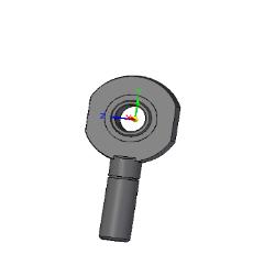
It can be known as a Rose joint or spherical bearing is essentialinafixtureforthemovementofthearmandthe upper holding of the fixture while keeping it aligned and reducing friction. The spherical design can handle slight angular misalignments, ensuring the upper holding turns freely during tests. By reducing friction, it ensures accurate and reliable test results as shown in figure 3(a). T-jointasshowninfigure3(b)keepstheupperholdingof the fixture stable and properly aligned. It has a round opening.Thedesignincludesspecificshapesandsupports to provide strength while keeping the part lightweight. This ensures the upper holding is securely attached, reducing vibrations and improving the performance. The material and build of this part are crucial to handle the stressesandconditionsduringflight.


a) Rose joint b) T-joint c) Support clamp
Fig 3: Differentjointsandclamps
The C clamp (fig 3(c)) in the support clamp is assembled with the rose joint with the support of a nut andbolttoholditsteadily.Thatsupportclampassemblyis the connection between the arm support and the upper holding of the fixture. This is a major load-bearing component in this assembly, where it bears the load of upperfixturealongwithmotorandpropellers.
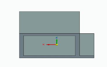
A motor mount as shown in figure 4(a) is attached to a gearboxmount,whichisattachedtothemotor.Thissetup isimportanttoholdthegearboxandmotorwhilekeeping everythingalignedandstable.Themountisdesignedtobe securely attached to the bottom mount providing strong support.Thegearboxhelpsadjustthespeedandtorqueto fit the propeller's needs. This component is built to be durableandreliablewhichiscrucialformaintaininggood performanceandhandlingthestressesduringUAVflights.


Fig 4: Differenttypesofmounts
The bottom mount of a UAV propeller fixture as shown in figure 4(b) holds the motor and supports the upperfixtureprovidingastablebaseforthewholetesting setup. Its design ensures a solid foundation reducing vibrationsandmovementduringtests.Thebottommount securely holds the motor, which is important for keeping the propeller aligned and the tests accurate. It fits well with the upper fixture creating a reliable testing environment.Insummary,thebottommountiscrucialfor the stability and accuracy of the propeller tests, supportingboththemotorandtheupperfixture.
The assembly as shown in figure 5 includes both the upper and bottom mounts, forming a complete structure that securely holds the propeller during tests. It provides a stable base and strong support for the motor and propeller minimizing vibrations and movement to ensure accurate and reliable test results. Made from durable materials like aluminium or steel, the fixture can withstandtheforcesgeneratedduringtestingmaintaining its strength and performance. The design of the fixture allows it to accommodate different propeller sizes and configurations, making it versatile for various testing setups. Additionally, it is easy to assemble and disassemble, allowing for quick setup and adjustments during testing. Overall, this final assembly is crucial for providing a reliable and precise testing environment ensuringthepropellerissecurelyandcorrectlypositioned forperformanceevaluations


International Research Journal of Engineering and Technology (IRJET) e-ISSN: 2395-0056
Volume: 12 Issue: 03 | Mar 2025 www.irjet.net p-ISSN: 2395-0072
The real-time multi-body dynamics of the UAV propeller fixture is carried out using the MSC Adams softwarewheretheresultshavebeenextractedwhichare very near to the experimental results. Once the 3D model of the design has been designed using the Siemens Solid Edge software the model is imported to the Adams software first, then bodies are defined as fixed or flexible. Once that is done, the materials are assigned along with thejointsandconstraints, whereconstraintslike revolute joints, prismatic joints, or spherical joints are assigned. Next, the external and internal forces such as gravity, aerodynamicforces,andspringforcesareapplied.
Simulation setup is done by specifying the positions, and orientations of the bodies. Boundary conditions are defined with the constraints and drivers that dictate how the system can be controlled and how the system will be moved. Dynamic analysis to examine the system's responsestotheangularvelocity,forces,andtorquewhich givesusthereal-timesimulationoftheforcesandmotion. Adams uses numerical analysis to solve the different governingequationstogetthemotionofthesystem.Postprocessing consists of the visualization of the simulation through graphs, animation, and various plots and representations and analyzing the data such as velocities acceleration force, and moments and the reports along withtheimagesandanalysisresults.
Thealuminumframesareusedtobuildtheupperbodyof the fixture and the other parts are mostly made up of stainless steel. Once the setup was ready we attached different force,torque,and motionsensorsto findoutthe pitching,androllingmovement.Theothersensorsarealso usedtofindtheforceandtorqueactingonthepropellers. Thepowerwasgiventothemotorstogivethemovement for the upper holding of the fixture where we altered the power to each motor according to our needs to find out thepitchingandrollingmovements.
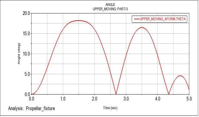
The first simulation result is discussed for the pitching and rolling movements in the upper moving part of the fixture where it is compared with the experimental values. In simulation we got 28° during the pitching movement and 17° during the rolling movement and the experimental values are 30° and 20° respectively. This result helps us to analyze experimental values with the simulation data and compare the aerodynamic forces acting during pitching and rolling moments. The data obtainedherecan beutilizedtovalidateandoptimizethe system if needed in the future for comparing and making the changes in the design of the fixture. Here the curve reaches the maximum of 30° in 1 second during the
pitching movement, then it declines near to 0° within 3 seconds. All these changes depends on the power of the motor being used. Same happens during the rolling movementaswelljustthedegreeofchangeisdifferentin thiscase.


Fig 6: Anglevstimegraphofpitchingandrolling movementdemonstration.
The forces that were analysed during the simulationareshowninfigure7aredifferentineachjoint. Out of 3 joints one joint touched a maximum of 415 N in the negative direction and 300 N in a positive direction during the pitching movement and 45 N in a positive direction and 140 N in the negative direction during the rolling movement. The forces acting on each joint are constantly being varied in the joints over the period of time. This helps us to understand the dynamic behaviour of the fixture under the various loads and by identifying the force at each point helps us to understand the stress points of the fixture and take the necessary action if required. During the full run, the force seems to be most stablealongthetimeatmostofthepoints.

International Research Journal of Engineering and Technology (IRJET) e-ISSN:
Volume: 12 Issue: 03 | Mar 2025 www.irjet.net


Fig 7: ForcevsTimegraphforjoints1,2,3duringpitching androllingmovementdemonstration
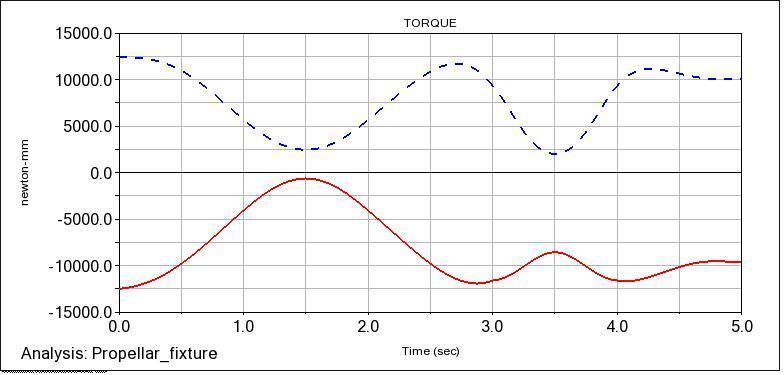
Comingtothetorquewhichisshowninfigure8is 21000N-mminthepositivedirectionand36000N-mmin the negative direction during the pitching movement and 12500N-mminthepositivedirectionand12000N-mmin thenegativedirectionduringtherollingmovement.Allthe data is analysed for 5 seconds run during the simulation and the time can be changed for higher or lower time for future simulations or trials. During the pitching movement, all three arms are operational and show different torque in each arm which indicates the oscillatory behaviour and observes the vibrations in the arm. When it comes to rolling motion, only two arms are operational and the phase relationship helps us to understand the vibrational characteristics of the system, this is very crucial during the designing of the systems whichhelpsustominimizethevibrationsandsynchronize the motions. Overall, the graphs show performance and identifypotentialissuesandoptimizethedesign.


Fig 8: Torquevstimegraphinthearmduringpitchingand rollingmotiondemonstration
Table 1: Experimentalandsimulationvaluesforpitching androllingmoments
Moment 20 17
Table 2: Simulationvaluesforthepitchingmoment

Volume: 12 Issue: 03 | Mar 2025 www.irjet.net
Table 3: Simulationvaluesforrollingmoment
The values of the load acting in the joints, Potential energyineacharmKineticenergyandtheangularvelocity which is given as input is listed in the table 1, 2 and 3 for pitching and rolling movements. The angular velocity is decided from the chart which is taken from the standard motorandgearboxcombination.Thisangularvelocitycan be changed and simulate to find out the various possible outcomes.
In conclusion, the comparison between experimental andsimulationresultsforpitchingandrollingmovements, as well as the forces and torque exerted on the arms during these movements, has provided valuable insights into the performance of the propeller testing fixture design. For pitching movement, the experimental and simulationresultsshowedcloseagreement,withvaluesof 30 deg/sec and 28 deg/sec, respectively. Similarly, for rollingmovement,theexperimentalandsimulationresults wereingoodagreement,withvaluesof20deg/secand17 deg/sec,respectively.
Additionally, the analysis of forces and torque during pitching movement revealed variations from -400 N to 300 N and -35,000 N-mm to 20,000 N-mm, respectively. Similarly,duringrollingmovement,theforcesrangedfrom -115N to48N,andtorque rangedfrom -12,500N-mm to 12,500N-mm.Theconsistencybetweenexperimentaland simulation results, along with the observed force and torque profiles, demonstrates the effectiveness of the propeller testing fixture design. These findings provide a strong foundation for further research and validation opportunities.
Future research could focus on refining the design parameters of the propeller testing fixture to optimize performance, enhance stability, and ensure safety. Additionally,furthervalidationstudiescouldbeconducted underdifferentoperatingconditionsandenvironmentsto assesstherobustnessandversatilityofthefixturedesign. Overall, the promising results obtained from the simulations open avenues for continued research and development in propeller testing methodologies, ultimately contributing to advancements in UAV technologyandaerospaceengineering.
[1] Gene Patrick Rible, Nicolette Ann Arriola, Manuel Ramos Jr. “Modeling and Implementation of Quadcopter Autonomous Flight Based on Alternative Methods to Determine Propeller Parameters”, Advances in Science, Technology and Engineering Systems Journal Vol. 5, No. 5, 727-741(2020)
[2] Patrik KÓSA, Marián KIŠEV, Lukáš VACHO, Ladislav TÓTH, Martin OLEJÁR, Marta HARNIČÁROVÁ, Jan VALÍČEK, Hakan TOZAN “Experimental Measurement of a UAV Propeller's Thrust”, https://doi.org/10.17559/TV20201212185220
[3] J.C. Bell; M. Brazinskas; S. D. Prior; C. Barlow; M. A. Erbil; M. Karamanoglu , “ Development of a Test-Rig for Exploring Optimal Conditions of Small Unmanned Aerial Vehicle Co-Axial Rotor Systems”, JOURNAL OF AIRCRAFT Vol.46,No.1,January–February2009
[4]StephenD.Prior “ReviewingandInvestigating the Use of Co-Axial Rotor Systems in Small UAVs” International JournalofMicroAirVehicles,Volume2·Number1·2010
[5] Z S Islami and F Hartono, “Development of small propeller test bench system, 2019 IOP Conf. Ser.: Mater. Sci.Eng.645012017
[6] Sivaprasad Kondapalli, Srirama Murthy Bellala, “Qualification of propeller by experimental and analytical methods” Anil Neerukonda Institute of Technology and Sciences,Vol.12,Iss:1,pp31-39.
[7]ZhitingJia,ZiyueZhao,JiansuQu,yanli,“Studyofstatic torque measurement device for composite variable pitch propeller blades” Vol 12282, 2021 International conference on optical instruments and technology: optoelectronic measurement technology and systems; 1228218(2022),https://doi.org/10.1117/12.2616427.
[8] Dongdong LUO, Shenzhen(CN), Wenbing SU, “Foldable propeller, power assembly and unmanned aerial vehicle” AUTEL ROBOTICS CO . , LTD . , Shenzhen ( CN ), No. PCT/CN2018/082659,filledonApril11,2018.

International Research Journal of Engineering and Technology (IRJET) e-ISSN: 2395-0056
Volume: 12 Issue: 03 | Mar 2025 www.irjet.net p-ISSN: 2395-0072
[9]MohamedH.Eldegwy,MohamedA.Hetta,MostafaR.A. Nabawy and Osama Mohamady,”Experimental Investigation into The Performance of UAV Propellers at Low Reynolds” Numbers Aerospace Engineering Department,FacultyofEngineering,CairoUniversity,Giza 12613,Egypt.
[10] Adam Smedresman, Derrick Yeo, and Wei Shyy”,Design,Fabrication,Analysis,andTestingofaMicro Air Vehicle Propeller”, Department of Aerospace Engineering, University of Michigan, 29th AIAA Applied Aerodynamics Conference 27 - 30 June 2011, Honolulu, Hawai.
[11] Willem A. Anemaat, Menco Schuurman, Wanbo Liu, Alex A. Karwas, “Aerodynamic Design, Analysis and TestingofPropellersforSmallUnmannedAerialVehicles”, 55th AIAA Aerospace Sciences Meeting, 9 - 13 January 2017, Grapevine, Texas, https://doi.org/10.2514/6.20170721.
[12] Rokvam, Sondre Østli, Nils Petter Vedvik, Luca Savio, and Andreas Echtermeyer. 2023. "Designing Composite Adaptive Propeller Blades with Passive Bend–Twist Deformation for Periodic-Load Variations Using Multiple Design Concepts" Polymers 15, no. 12: 2749. https://doi.org/10.3390/polym15122749.