Analysis of stability of rock column between cut & cover Metro Station and NATM Tunnels
Swarup Maiti1, Prof. Dr. Sandeep Potnis2
1PG student, MIT World Peace University, Pune, India

2Head, School of Tunnel Engineering, MIT world Peace University, Pune ***
Abstract: Planning and accommodation of underground metro stations in available land areas is an important aspect of any metro project. Designer has to adopt the innovative solution for station design due to limited space. To accommodate the station box within the available area, station may have to be constructed with the combined construction approach of NATM and cut and cover. In this approach main station box is constructed with a cut and cover method and platform tunnel is constructed with a NATM method. The sequence of construction can be simultaneous or opening of tunnel is carried out from the cut & cover shaft or TBM tunnel excavation is done before station excavation. Any underground excavation has a major influence on the nearby existing structures. This paper covers the various aspects of ground response to the interaction between strutted excavation and NATM tunnel excavation. Study of integrated excavation is carried out with varying the width of rock column between station excavation and NATM platform tunnel. The variations in the geological stratification and impact of different construction sequences are investigated.
Key words- EarthRetainingSystem(ERS),secantpile,PlatformNATMtunnel,Surfacesettlement,Undergroundmetro,Rock column,cutandcoverstructures,deepexcavations.
1. INTRODUCTION
Indiahasseenahugedevelopmentinthemetrorailprojectsinthelast3decades.SeveralUndergroundMetroprojectshave beenconstructedandmanyareintheunder-constructionandplanningphase.Planninganddesignoftheundergroundmetro stationisachallengingjob.Asmostoftheundergroundstationsareplannedinadenselypopulatedareatogainmorepublic ridership.Undergroundmetrostationsareusuallyplannedunderroads,emptyground.Planningofundergroundstationunder existingroadhasmajorissuei.e.,protectionofbuildingsadjacenttothemetrostation.Oneoftheundergroundmetrostations wereplannedinadenselypopulatedareainMumbai,onnarrowroads,andinthestationvicinity,severaldilapidatedbuildings werepresent.HencefewstationswereplannedtoconstructwithamixedmethodofcutandcoverforstationboxandNATM methodfor Platformtunnel. Owing to the presenceof buildingsinthevicinity of thestation footprintthe possibilityofa completecutandcoverstationwasnotfeasible.HencetheinnovativeideaofintegratedNATMplatformtunnelandcut&cover stationexcavationisadoptedinmanystations.Thisstudyinspiresbythesamecasewherethestationboxisbeingexecutedby adoptingthemethodologyofcutandcovermethodandtheplatformisbeingconstructedbytheNATMtunnelingmethod[1]. ConnectionwithstationboxandNATMplatformismadewiththeintermediatecrosspassagesatregularintervals.Research studyemphasisonthebehaviorofintegratedcutandcoverexcavationandexcavationofNATMtunnelusingpredictable elementofsoil-structureinteractionanalysis.Theresultsresponseofgroundunderdifferentparametersarepresentedinthis paper.
Alignment of the underground metro is generally planned through a heavily built-up urban area. Many times, important LandmarksandHeritage structuresarelocatednearby ordirectlyabove thetunnel alignment. Owing toland availability constraints,costofprivateproperties,inadequateavailableroadwidth,andtheveryimportantpresenceofHeritagebuildings planning,anddesignofmetroalignmentisimportantpartofanyundergroundmetroproject.
ThealignmentofanundergroundmetroprojectisconstructedwithtwintunnelsbyTunnelBoringMachine(TBM)connecting two stations. The underground stations or shaft are generally proposed to be constructed by adopting the cut & cover constructionmethodology,andNATMmethodofconstructionandgroundsettlementsaretobelimitedtoprotectexisting buildings.
Duepresenceofahigh-watertable,highrisebuildingimposesahighersurchargeloadwhichleadstohighersettlements; however,thedesignerhastocontrolitwellwithintheacceptablelimit.Inhighwatertableareasgenerally,excavationisdone withawater-tightretainingsystemtopreventgroundsettlementsduetoseepageduringexcavations.Tomaintainthewater tableinthenon-excavatedareaproposaloftherechargewellmayberequired.
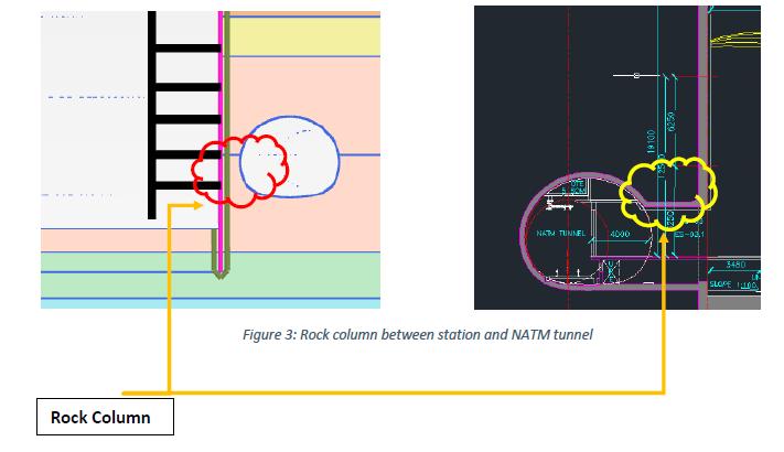
Thepurposeofthisstudyistocarryouttheassessmentofrockcolumnbetweencut&coverstationandNATMtunnelsofone UndergroundMetroprojectinMumbai.Thispaperprovidesananalysisforsafetyofrockcolumn.
InPreliminarystage,therockcolumnwidthwas2.6mbasedontenderstageGIR.
During construction stage, after preparing actual GIR, Geotechnical parameters were revised, and rock quality is consideredtobepoorw.r.tTenderGIR.Rockcolumnwidthneededtoincreaseforstabilityofsupportingsystem duringexcavation.
Followinganalysesareperformed–
a) RockColumnwidth4mbetweencut&coverStationandNATMTunnel
b) RockColumnwidth5mbetweencut&coverStationandNATMTunnel
2. Literature review

ThesettlementdatafromTBMtunnelinginvaryinggroundconditionwhicharerepresentativeoftheMumbaigeology are analyzedandpresentedinthissection.
Intheyear1958,Martoshasexaminedthesettlementtroughshapeonminingexcavations,whichwasrepresentedbyaGaussian orNormaldistributioncurve.
Onthelaterstage,Schimdt,andPeckintheyear1969hasshownthatsurfacesettlementintheabovetunnelswereexperienced inasimilarform. O’ReillyandNewhasdevelopedtheGaussianmodeintheyear1982,byassumingthatthegroundlosscould berepresentedbyaradialflowofmaterialtowardsthetunnelandthatthetroughcouldberelatedtothegroundconditions throughanempirical“troughwidthparameter”(K).Themodelwasguidedbyananalysisofcasehistorydata.
Duetotheaboveassumptions,itwaspossibletodevelopequationsforverticalandhorizontalgroundmovementsthatwerealso presentedintermsofgroundstrain,slope,andcurvature(bothat,andbelow,thegroundsurface).Fromthereon,theequations are being widely used to access the potential impact of tunneling works during the design stage. The base equation is as mentionedbelow.
WhereS=groundsettlementatapoint;Smax=maximumgroundsettlement;A=cross-sectionalareaoftunnel;V=%ofground lossassumingthegroundisincompressiblei.e.,V=Vs/A,whereVsisthevolumeloss;k=empiricalconstantalsocalledas troughwidthparameter;andZ=depthoftunnelaxis.
Foranexample,todetermine/predictthegroundmovementonlythefollowingparameterswereadopted/considered.
Clough,O’RourkeandPeckadoptedtheexcavationdepthtodeterminegroundmovementasitistheonlyparameter.
To predict the ground movement wherein the excavation depth is the main parameter in the formula, Bowles consideredtheareacoveredbylateralwallmovementasaparameter.

Topredicttheconcavetypeandspandreltypeofsettlementprofiles,HsiesandOuusedtheexcavationdepthastheonly parameter.
OsmanandBoltonadoptedtheplasticzone,whichiscompletelyrelatedtotheexcavationdepthandwastheonly parameterusedintheprediction.
3. DESIGN OF TEMPORARY SUPPORT SYSTEM AND GEOLOGY

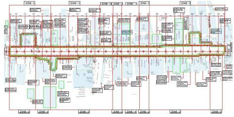
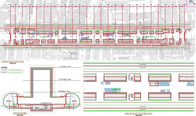
Incombinationofcut&coverandNATMundergroundmetrostationconstruction,thereisaccessTunnelatregularintervalfor connectionbetweenthem.DuringexcavationforaccesstunnelandPlatformtunnelhighstressesaroundtheopeningaretobe checkedandcontrolled.Therefore,rockcolumnstabilitycheckisveryimportant.ThisstudyhasbeenperformedusingPLAXIS2Dfiniteelementanalysisprogram.
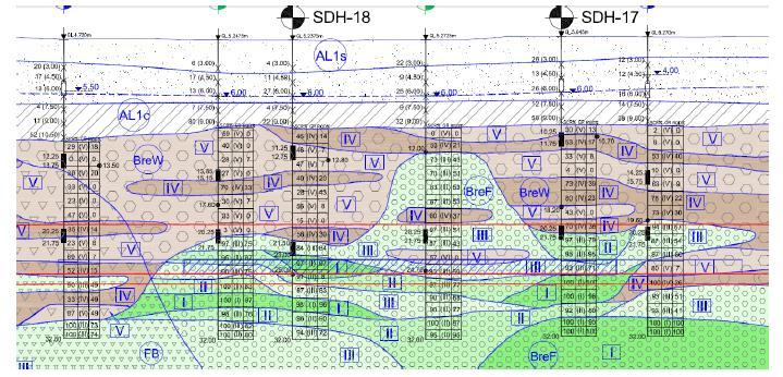
AsperrequirementofEmployer,allthetunnelsectionsshallbecompliedwithScheduleofDimension(SOD).Theprofileof Tunnel may be circular, D-Shape or horseshoe and it depends on the ground conditions. Here horse-shoe shape tunnel is considered.CrosssectionalareaofTunnelisaround90.4sqm.,widthis11.2mandheightis10m.Overburden(soilmixedwith rock)of18misconsideredabovetunnelcrowninthisanalysis.ActualgeotechnicalprofileandinformationiscollectedfromGIR ofproject.ClassIVandVrockareidentifiedatfinalexcavationlevelwhichis28mbelowground.Forparallelconstructionand stabilityofthesystem,allthesecantpileareterminated4mbelowthefinalexcavationlevel.
Forstabilityanalysis,followingparametershavebeenconsideredinthemodel–
Co-efficientoflateralearthpressure=0.5
ThesoilismodeledbyusingMohr-Coulombmaterialmodel
Using Mohr-Coulomb material model, Rock mass is modelled where the strength and deformation properties are derivedusingHoekandBrowncriterionbasedonHoekandTorres(2002).
Watertableatgroundlevel
Secantpile(combinationofM40-RCCandM10-PCC)of1mdia,32mdepthand170mmoverlap.
Allpilesare32mdepthi.e.,4mbelowfromfinalexcavationlevel.
5levelstrutsareusedforsupportingofsecantpile,horizontalspacing10mc/candverticalspacing4.5mc/c.
Followingconstructionstagesareconsideredinthemodel:

4. METHODOLOGY
Analysisofthestabilityofrockcolumn,propertiesoftemporarysupportsystemandconstructionsequencearediscussedhere.
ThegeotechnicalsoftwarePLAXIS2Dwasusedtostudythesoil-structureinteractionbetweenthecut&coverstructureand NATMtunnelanditsimpactonrockcolumnstability.Thesoftwarewasusedtoprovidethefactorofsafetyofrockandsoilfor theproposedconstructionsequence.

5. ANALYSIS AND RESULTS

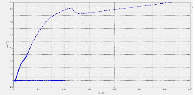
Initiallyrockcolumnof2.66mwidthisanalyzed.Theanalysiswascarriedoutforthiscolumnwidth,anditwasobservedthatthe rockcollapsesinthisscenario.Hence,thewidthbetweenthecut&coverstationboxandNATMtunnelwasincreasedtohave lowerconcentrationofstressesintherockcolumn.
Followinganalysiswereperformed–
a) Rock column width of 4m between station and NATM Tunnel
PLAXISoutputforRockcolumnstability(4mwide)considering30%Relaxation


Maximumvalue=1822kPa
Minimumvalue=-9982kPa
Maximumvalue=1895kPa

Minimumvalue=-10.10*10^3kPa


a) Rockcolumn width of5m
station andNATMTunnel
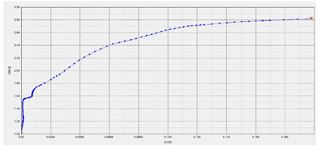
PLAXISoutputforRockcolumnstability(5mwide)considering30%Relaxation


Maximumvalue=1673kPa


Minimumvalue=-8157kPa
Maximumvalue=1787kPa
Minimumvalue=-9067kPa

6. DISCUSSION AND CONCLUSION
To understand the complex soil-structure interaction Two-dimensional FEM modelling is used, involving cut & cover excavation with an adjacent NATM Tunnel. It is observed that the excavation of Tunnel adjacent to the cut & cover box excavationinfluencesthegroundbehavioralongwiththebehaviorofearthretainingsystem.
Geologicalstratificationhasmajorimpactontunneldesign.Increaseinrockcolumnwidth,thereisreduceofgroundsettlement andreduceoftotalstress.
Excavationoftunnelwillcauseashort-termlossofgroundwaterduetowhichtheunbalancedloadpathisimposedonearth retainingsystemofsupportingcut&coverexcavation.Theunbalancedloadingconditionsincreasesthedisplacementofsecant pileonthefairsideoftunnelexcavation.Thelossofgroundwatercanbecontrolledbyinstallingagroutcurtainaroundthe tunnelprofilebeforethestartofexcavationalongwithrechargewells.
Itisobservedthatthetunnelexcavationinducesadditionalstressontherockcolumnandcausestherockcolumndeformation. After excavation of tunnel, surface settlements increase immediately. The maximum surface settlements are observed immediatelybehindthesecantpile.Thewidthofrockcolumnappearstohavenomajoreffectonthemagnitudeofmaximum surfacesettlements.Theslopeofsettlementtroughisinfluencebytherockcolumnwidth.
Adjacentcut&coverexcavationhasaninfluenceonthebehavioroftunnelexcavation.Tunnelliningwassubjectedtohigher deformationatthefacewalladjacenttotheopenexcavationanddeformationincreasedwithreductioninwidthoftherock column.
Fromtheanalysis,itisconcludedthattheminimumwidthofrockcolumnbetweenstationandNATMtunnelshallbe5mto achieveFOSof2.8.Asensitivityanalysiswascarriedoutfor4mwiderockcolumn,andtheanalysiswasnotsuccessful(i.e., FOS<2.5),confirmingthattheminimumwidthofrockcolumnshallbe5mforthesegeologicalconditions.
REFERENCES
[1] MechanizedTunnellinginUrbanAreas–DesignmethodologyandconstructioncontrolbyVittorioGulielmetti,Piergiorgio Grasso,AshrafMahtab&ShulinXu

[2] Martos,F.1958.Concerninganapproximateequationofthesubsidencetroughanditstimefactors.InternationalStrata ControlCongress,Leipzig,(Berlin:DeutscheAkademiederWissenschaftenzuBerlin,SectionfurBergbau),191-205
[3] Peck, R. B. 1969. Deep excavation and tunneling in soft ground. 7th International Conference on Soil Mechanics and FoundationEngineering,MexicoCityState-of-the-Artvolume,225-290
[4] O’Reilly,M.P.andNew,B.M.,1982.SettlementsabovetunnelsintheUnitedKingdom–theirmagnitudeandprediction. Tunneling’82,London,173-181.
[5] CloughGW,O’RourkeTD.Construction-inducedmovementsofinsituwalls.Proceedingofthedesignandperformanceof earthretainingstructures,ASCEspecialconference,Ithaca,NewYork:1990,439-70.
[6] BowlesJE.Foundationanalysisanddesign.4thed.NewYork:McGraw-Hill:1986
[7] HsiehPG,OuCY.Analysisofnonlinearstressandstraininclayundertheundrainedcondition.JMech2011;27(2):201-13
[8] OsmanAS,BoltonMD.Groundmovementpredictionsforbracedexcavationsinundrainedclay.JGeotechGeoenvironEngg 2006;132(4):465-77.
[9] ChakeriH,HasanpourR.,HindistanM.,UnverB.(2010).Analysisofinteractionbetweentunnelsin
[10] thesoftgroundby3Dnumericalmodeling.BulletinofEngineeringGeologyandtheEnvironment,70:439-448.
[11] HoekE.,Carranza–TorresC.(2002).Hoek–Brownfailurecriterion,Edition1,In:Proc.NARMS-TACConference,Toronto, 1,267-273.
[12] KimS.H.,BurdH.J.,MilliganG.W.E.(1998).Modeltestingofcloselyspacedtunnelsinclay.Geotechnique.48(3),375-388.
[13] LiuH.Y.,SmallJ.C.,CarterJ.P.,WilliamsD.J.(2009).Effectsoftunnelingonexistingsupportsystemofperpendicularly crossingtunnels,ComputGeotech.36(5),880-894.
[14] PerriG.(1994),Analysisoftheeffectsofthenewtwin-tunnelsexcavationveryclosetoabigdiametertunnelofCaracas Subway.In:SalamA(ed)Tunnelingandgroundconditions,Balkema,Rotterdam,83-90.
[15] ShahrourI.,MrouehH.(1997).Three-dimensionalnonlinearanalysisofacloselytwintunnels.In:Sixthinternational symposiumonnumericalmodelsingeomechanics(NUMOGVI),Montreal,QC,Canada,2,481-487.

BIOGRAPHIES
Mr. Swarup has completed B. E. (Civil Engineering) from IIEST, Shibpore, Howrah in 2004. After that continuous more than 19 years working in Design and Construction of underground & elevatedMetroRailProjectinIndia as Engineering Manager Mr Swarup is Final year M Tech –Tunnel Engineering student of MIT, Pune He is pursuing Post Graduate project management fromNICMAR,Hyderabad.

