Structural Analysis of Unbonded Post-Tensioned Shear Wall
Kshitija V. Managaonkar1, Dr. Praphulla K. Deshpande21M. Tech Student, Structural Engineering- Applied Mechanics Department, Government College of Engineering, Karad, Satara, Maharashtra, India.
2Professor, Applied Mechanics Department, Government College of Engineering, Ratnagiri, Maharashtra, India.

Abstract- The project examines the significance of utilising a shear wall as a key structural element. The goal of the current paperwork is to review numerous studies on improving shear walls and their response to lateral stresses, wind load and seismic forces. Shear walls respond as a progressive ductile failure and avoid brittle shear failure. In this paper, a building was designed without the shear wall, with a shear wall and with a prestressed shear wall using ETabs. All these 3 types of buildings are compared based on displacement, story drift and % steel requirement. The results show a significant decrement regarding considered parameters. The steel requirement is decreased from 0.42% to 0.26% for prestressed shear walls.

Keywords: Shear wall, prestressed, unbonded post-tensioned, precast, seismic analysis, lateral loading.
• INTRODUCTION:
Inmulti-storybuildings,shearwallsaremoreeffectiveinresistinglateralloads.Shearwallsconsistingofsteelandreinforced concrete are kept at key locations of multi-story buildings that are constructed with consideration for wind and seismic pressure. Significant research was conducted on several shear wall-related topics, including shear walls can be used in the constructionofanykindoftallbuildingthatissusceptibletolateralforceslikeearthquakesandwind.Shearwallscanbe used to retrofit existing constructions as well as to resist lateral loads. Researchers' cyclic stress experiments reveal that internal shear walls are more effective than external shear walls . If shear walls are sufficiently strong, they will transmit these horizontal forces to the component below them in the load path. These additional elements in the load path could be additional floors, slabs, foundation walls, or shear walls. Shear walls also offer lateral stiffness to avoid excessive lateral movement of the roof or floor above. Shear walls that are sufficiently rigid will stop floor and roof framing members from slippingfromtheirsupports.Additionally,sufficientlyrigidstructurestypicallysustainlessnon-structuraldamage.Theoverall stiffnessisgreaterthanthesumoftheindividualstiffnesswhentwoormoreshearwallsarejoinedbyasystemofbeamsor slabs.
Openings typically appear in vertical rows along the height of the wall, and connecting beams hold the cross-sections of the wallstogether.Coupled shearwallsare the name given to suchshear walls. The load-deformation behaviour ofprestressed
concrete wall panels was investigated experimentally. Three main variables the type of wall panel, slenderness ratio, and intensity of the load were used in the study. The types of wall panels examined included ribbed and flat walls. With an increase in wall width for flat wall panels, both the ultimate load and deflectional stiffness dramatically rise . Precast shear wall panels come with a variety of bottom face joints (horizontal and vertical) and side face joints. Since shear forces in the wall transferto thestructurethroughthesehorizontal jointsonthe bottom face,the bottomface iswhere the moststressis generated. Analysis of the various bottom face joints of precast shear wall panels is crucial. It is crucial to analyse the combined behaviour of earthquake-related in-plane and out-of-plane forces. Different kinds of horizontal connections' geometriesresultinvariouskindsofshearresistanceforidenticalgroutcharacteristics.Atthesamedegreeofload,theshear capacity of the multiple-key connection is larger than that of the simple surface connection . The use of rectangular precast panels stacked along horizontal joints and unbonded post-tensioning (PT) strands inserted into ungrouted ducts to connect thepanelsto the foundation isproposedasa precastpost-tensionedconcrete wall system withadded friction- andyieldingbased energy dissipation. Specially created yielding-based and friction-based energy dissipation components are externally connected at the base of the wall using thru-bolts, enabling the replacement of these components after a significant earthquake,allowingthewalltoregainthemajorityofitsoriginallateralstrength,stiffness,andenergy-dissipatingcapacity.
• METHODOLOGY:
Flexuralbehaviour,asopposedtoshearslidingatthebase,shoulddictatethelateralloadbehaviourofawell-constructedUPT wall.Insteadofconcretefailure,orbehaviourcausedbyunder-reinforcement,theflexuralstrengthshouldberegulatedbyPT steel yielding. The limit states describe the lateral load behaviour of UPT walls under the assumption that under reinforced flexuralbehaviourcontrols.
• Detailing of Specimen:

In order to analyse the shear wall, Etab software was used. The modelling was done for G+10 floors. The modelled building was executed at Mumbai, Maharashtra. Whereas same loading conditions were considered. The loading contemplatesdeadload,liveload,windloadandearthquakeload.Thecomparisonwasdonebetweenthebuildingwithno shear wall, the building with RC shear wall and last the building was having a prestressed shear wall. So, after the modellingwasdone,theanalysiswasdoneonthebasisofdisplacementofbuilding,storydriftand%steelrequirement.

• Analytical Analysis

Firstly,theloadcalculationisdone,i.e.gravityload,live load,seismic forcesandwindloadielateralforces.The location consideredforseismiczoneisMumbai.Further,thenormalRCshearwallisdesigned.Andforprestressedshearwall,the basic consideration was the wall lied into precast unbonded post-tensioned shear wall category. Therefore, the prestressedwallwasdesignedforthermalbowing,inwhichpotentialthermalbowis0.5andresidualbowis0.28.Further slenderness effectwasalso calculatedfor thatsecondorderP- analysiswasdone byhandcalculationaswell asthrough Etabsoftware,toavoidstabilityfailure.Afterthatfromthecalculatedstresses,requirednumberofstrandswascalculated
• RESULT AND DISCUSSION:
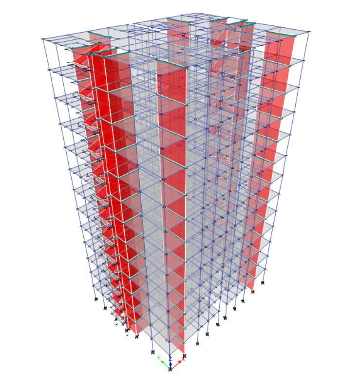
The modelled building had the shear wall in x and y direction; therefore, it resists drift n displacement in both the directions.
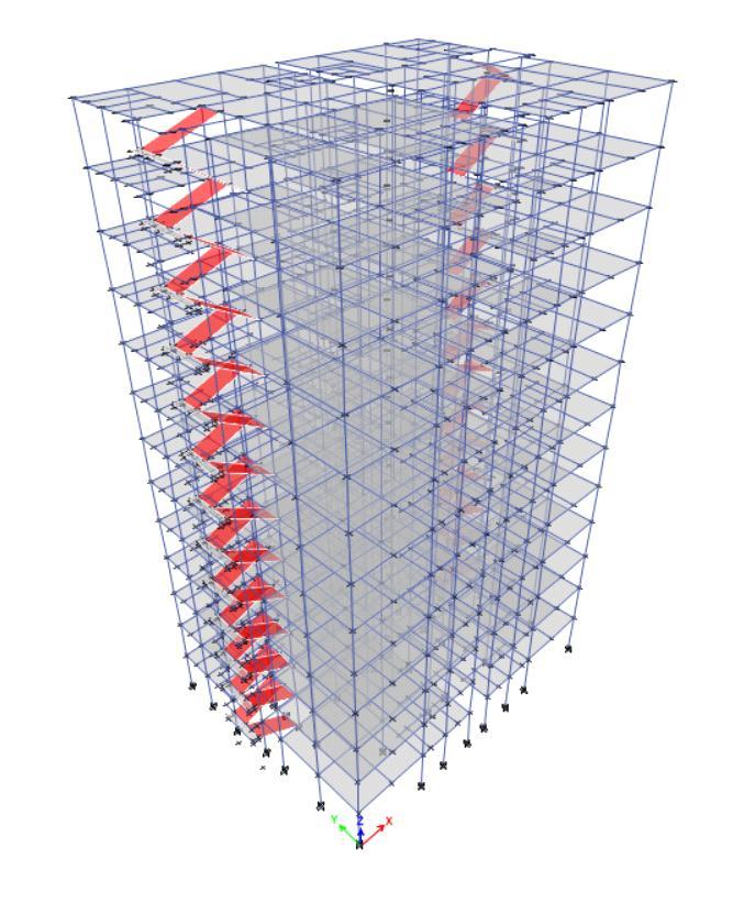
Theabovefigureshowsthebuildingmodelinwhichunbondedposttensionedshearwallaredesigned.Whereasthenext figure shows the displacement of building in finite element analysis after the load was applied. Therefore, the deformed building figure shows that maximum displacement atthetopmostfloorof buildingandgoesgraduallydecreasingalong thelowerfloors.


Displacement due to wind load
The plotted graph shows the increment of displacement as the elevation increases. The building without SW shows a displacement of 42.5mm. Whereas the building with SW shows a displacement of 32.5mm and the prestressed shear wall is displacedby16.78mm.DisplacementcheckisH/500=45.5/500=91mm.
Story Drift
Theplottedgraphshowsthedecrementofstorydrifttowardsthelowerstory.ThebuildingwithoutSWshowsadriftof494.2 WhereasthebuildingwithSWshowsamaximumdriftof436.4andtheprestressedshearwallbuildingwasdriftedby400.6. Asaconsequence,theusingPTshearwalldoesnotallowabuildingtodisplacefromitsoriginalplaceevenafteritsimpacted byvarioustypesofloading.Thus,PTshearwallaidsinresistingsturdyloadingconditions.

Fig
AComparativeAnalysis
wallbasedonsteelrequirementandsteelprovide Thebuildingwithoutashearwallrequiresa%steelof0.42%.Whereasthebuildingwithoutashearwallrequiresa%steelof 0.25%.Thedifferencebetweentherequirementis0.17%.Thisshowsthat37%ofsteelisbeenreduced,duetotheapplication ofaprestressedshearwalls.
• CONCLUSION:
• There are various benefits of integrating PT tendons into traditional shear walls, such as increased stiffness, strength, stability, damage control and reduced lateral displacement. The lateral load capacity and effective stiffness are found observedtobeincreasedinthepost-tensionedshearwallsystemasthePTstresslevelincreases.
• Unbondedpost-tensionedprecastwallscansoftenandundergolateraldriftwithlittledamage.
• The overall reinforcement area can be reduced by using unbonded post-tensioned reinforcement and wall ductility is observedtobeenhanced.
• The failuremode of the hybridshear wall with PT tendonsis primarilycontrolled bytheyieldingofthe PT strands.The absence of PT force can result in inadequate restoring, leading to excessive uplift, horizontal slip, and degradation of lateralstrengthandstiffness.
• The modal displacement is decreased when the shear wall is used, whereas it shows a significant decrement when prestressedshearwallisused.

• Even there is noteworthy decrement of the steel requirement, in this case the steel requirement is decreased by 40%, consequently,itaidsincostefficiency.
• FUTURE SCOPE:
Further, the design can be done for vertical prestressing as well as for the combination of horizontal and vertical prestressing.Thevariationloadingcanbedoneusingseismicforces.Eventheanalysiscanbebasedonnonlinearanalysis
• REFERENCES:
[1] V.SairamKumarN,S.BabuR,U.KrantiJ,andA.Professor,“ShearWallsAreviewShearwalls-Areview,” International Journal of Innovative Research in Science, Engineering and Technology (An ISO, vol. 3297, no. 2, 2007, [Online].Available:www.ijirset.com

[2] K.Nagarathna,B.RameshBabu,G.R.Yadav,andM.Tech,“AnalysisandDesignofMultistoriedBuildingWithShear Wall,” International Journal of Innovative Research in Science, Engineering and Technology (An ISO,vol.3297,no.11, 2007,doi:10.15680/IJIRSET.2016.0511172.
[3] “Responseofstructuresto earthquakes:analysisofshear walls,”
X.
[4] M. A. Issa, “Durability of fiberglass pretensioned beams View project.” [Online]. Available: https://www.researchgate.net/publication/237578602
[5] PCICommitteeonParkingStructures.andPCICommitteeon Parking Marketing&Promotion., Precast prestressed concrete parking structures : recommended practice for design and construction
[6] R. S. Labadan, “Design Of Post-Tensioned Prestressed Concrete Beam Using Excel Spreadsheet With Visual Basic Applications,”2016.
[7] A.B.KumarCandD.M.K,“COMPARITIVESTUDYBETWEENBOUNDARYELEMENTDESIGNANDUNIFORMSHEAR REINFORCEMENTINSHEARWALLINSEISMICZONEIV.”[Online].Available:www.irjmets.com
[8] H.R.SanghviandM.A.Dhankot,“ANALYSISOFPRECASTSHEARWALLCONNECTION-STATEOFTHEARTREVIEW.” [Online].Available:http://www.ijret.org
[9] “Post-TensionedConcreteShearWall,”2015.doi:10.5703/1288284315718.

[10] “Designing with Precast and Prestressed Concrete DESIGNING PRECAST CONCRETE 03 03 40 00 with PRECAST andPRESTRESSEDCONCRETE.”[Online].Available:www.pci.org,
[11] “PCIDesIgnHanDbook/seventHeDItIon14.1PCIStandardDesignPractice.”
[12] H. Wilden and Precast/Prestressed Concrete Institute., PCI design handbook : precast and prestressed concrete. Precast/PrestressedConcreteInstitute,2010.
[13] F.MOLA Co-Advisor, J.I.Keileh,andL.A.Bd,“PolitecnicodiMilanoSchoolofCIVIL, ENVIRONMENTAL ANDLAND MANAGEMENT ENGINEERING Master degree in CIVIL ENGINEERING ANALYSIS, DESIGN AND MODELING OF UNBONDEDPOST-TENSIONEDCONCRETESHEARWALLSINSEISMICAREAS,”2014.
[14] X. Li, Y. C. Kurama, and G. Wu, “Experimental and numerical study of precast posttensioned walls with yieldingbasedandfriction-basedenergydissipation,” Eng Struct,vol.212,Jun.2020,doi:10.1016/j.engstruct.2020.110391.
[15] J. I. Restrepo, M. Asce, and A. Rahman, “Seismic Performance of Self-Centering Structural Walls Incorporating EnergyDissipators”,doi:10.1061/ASCE0733-94452007133:111560.
[16] “DETAILING FOR POST-TENSIONED General Principales Local Zone Design General Zone Design Examples from PraticePreface1,”1991.
[17] H.Gor,“DesignandConstructionofP/TConcreteStructures.”
[18] M.Vejvoda,“DesignofPost-TensioningBuildingStructures,”2020.
[19] F.J.Perez,M.Asce,;RichardSause,S.Pessiki,andA.M.Asce,“AnalyticalandExperimentalLateralLoadBehaviorof UnbondedPosttensionedPrecastConcreteWalls”,doi:10.1061/ASCE0733-94452007133:111531.
[20] H. A. D. S. Buddika and A. C. Wijeyewickrema, “Seismic Performance Evaluation of Posttensioned Hybrid Precast Wall-Frame Buildings and Comparison with Shear Wall-Frame Buildings,” Journal of Structural Engineering, vol. 142,no.6,Jun.2016,doi:10.1061/(asce)st.1943-541x.0001466.
[21] X. Lu, X. Dang, J. Qian, Y. Zhou, and H. Jiang, “Experimental Study of Self-Centering Shear Walls with Horizontal Bottom Slits,” Journal of Structural Engineering, vol. 143, no. 3, Mar. 2017, doi: 10.1061/(asce)st.1943541x.0001673.
[22] I.Gilbert,“DesignofPrestressedConcretetoEurocode2SecondEdition.”
[23] T.S.C.Institute, Handbook of Structural Steelwork Eurocode Edition Handbook of Structural Steelwork,no.55.2013. [Online].Available:www.steelconstruction.info
[24] “EN1998-1:Eurocode8:Designofstructuresforearthquakeresistance–Part1:Generalrules,seismicactionsand rulesforbuildings,”2004.
[25] BIS (Bureau of Indian Sandards), “General Construction in Steel – Code of Practice,” Is 800, no. December, p. New Delhi,2007.
[26] “GUIDEFORUSINGNATIONALBUILDINGCODEOFINDIA2016.”
[27] I.S.Institution,“CodeofPracticeforConstructionWithLargePanelPrefabricates,” Is : 11447-1985,1985.

[28] 318-19 Building Code Requirements for Structural Concrete and Commentary. American Concrete Institute, 2019. doi:10.14359/51716937.
[29] B.ofIndianStandards,“IS11447(1985):Codeofpracticeforconstructionwithlargepanelprefabricates.”
[30] J.K.WightChair et al.,“ConsultingMembersBUILDINGCODEREQUIREMENTSFORSTRUCTURALCONCRETE(ACI 318-05) AND COMMENTARY (ACI 318R-05) REPORTED BY ACI COMMITTEE 318 ACI Committee 318 Structural BuildingCode†Deceased,”2005.
[31] B. of Indian Standards, “IS 15917 (2010): Building Design and Erection Using Mixed/Composite ConstructionCodeofpractice.”
[32] B. of Indian Standards, “IS 15916 (2011): Building Design and Erection Using Prefabricated Concrete - Code of Practice.”
[33] B. of Indian Standards, “IS 15917 (2010): Building Design and Erection Using Mixed/Composite ConstructionCodeofpractice,”2010.
[34] B. of Indian Standards, “IS 14213 (1994): Code of practice for construction of walls using precast concrete stone masonryblocks.”
[35] B. of Indian Standards, “IS 10505 (1983): Code of practice for construction of floors and roofs using precast concretewaffleunits.”
[36] B. of Indian Standards, “IS 14142 (1994): Code of practice for design and construction of floors and roofs with prefabricatedbrickpanel.”
[37] B.ofIndianStandards,“IS6332(1984):Codeofpracticeforconstructionoffloorandroofsusingprecastdoublycurvedshellunits.”
[38] B. of Indian Standards, “IS 14215 (1994): Design and Construction of Floors and Roofs with Precast Reinforced ConcreteChannelUnits-CodeofPractice.”
[39] B. of Indian Standards, “IS 13994 (1994): Design and Construction of Floor and Roof with Precast Reinforced ConcretePlanksandJoists-CodeofPractice.”

[40] B. of Indian Standards, “IS 10297 (1982): Code of practice for design and construction of floors and roofs using precastreinforced/prestressedconcreteribbedorcoredslabunit.”
[41] B.(BureauofI.Standards),“IS10297(1982):Codeofpracticefordesignandconstructionoffloorsandroofsusing precastreinforced/prestressedconcreteribbedorcoredslabunit,” Is : 10297-1982,1982.
