Structural performance of 3D printing RC beams using internal and external strengthening methods
Amina Sherief1 , Athira Suresh21 Student,Dept. of Civil Engineering,ICET Mulavoor ,Kerala,India
2 Asst. Professor, Dept. of Civil Engineering, ICET Mulavoor,Kerala,India

Abstract
In this project 3D printed beams provided with internal and external strengthening methods were analyzed with the assistanceofANSYSsoftwareanditsfindingsarecomparedto achieve the better version of such beams. Validation is completed and is successful. After the validation models of strengthened 3D printed concrete (3DPC) beams were produced and results are compared with reinforced concrete beams. High strength wires are utilized for internal strengthening purpose. These wires were organized in numerous patterns and are analyzed to find out the better combination.Externalstrengtheningof3DPCbeamswithsteel plates installed on both sides of beams are also assessed. Beams with varying plate thickness and bolt arrangement patterns are explored.
Key Words: 3D printed concrete beams (3DPCB), internal strengthening, external strengthening, high strength wires.
1.Introduction
Among the additive manufacturing (AM) techniques for concrete now in use, three-dimensional concrete printing (3DCP)technologyseemstohaveattractedthemostinterest due to its general technological level and demonstrated profitability.Thedevelopmentof3DCPtechnologyhasledto theimplementationoftypicaldemonstrationprojects.2015 sawthe printing of an 11 m long, 5 m wide,and4 m high concrete structure by the Eindhoven University of Technology. In 2016, a 3DCP office located in Dubai also started operating.China Construction SecondBureauLTD produced a two-story, 7.2 m tall office building in 2019. Insteadofemployingprintedconcretecomponentstocreate theofficebuilding,3DCPwasusedon-site,in-situ.Aconcrete pedestrianbridgewasprintedbytheInstituteofAdvanced Architecture.
However,therearenumerousdifficultiesinusing3Dprinted concrete buildings in actual technical applications. With a high resistance to compression and a weak resistance to tensile and flexural pressures, concrete is a typical quasibrittle material AM is a good application for concrete. Its strengtheningmethodmustbecarefullyconsideredinorder to improve its mechanical properties. Freshly mixed concreteisextrudedfromthenozzlealongapredetermined
pathandpiledontopofoneanothertobuildabuildingusing 3DCP technology. Therefore, it is difficult to add vertical reinforcement in printed concrete walls. Additionally, printedplainconcretewallsarefragile,havealowultimate bearing capacity, and have a low level of crack resistance. However,inordertomeettherequirementsforbuildability, theworkabilityandcompactionof3Dprintedconcretemust berestrictedtoalowerlevel.
Although a numberof3DPC reinforcedtechnologiesseem promising, they are still in their infancy and principally requiremoreadaptabilitytoautomaticallyconstructvertical and horizontal components that adhere to the necessary internationalbuildingstandards.Themechanicalbehaviour of reinforced 3DcP members should, theoretically, be the sameasthatofconventionallyconstructedonesbecausethe additionofsteelreinforcementmakesupfortheconcrete's relativelylowtensilestrengthandflexibility.Totakethe3D printing process into account, the design concepts and models must be carefully reviewed. The shape-related mechanics, anisotropy, thin interfacial layers, potential sliding,andaweakerlinkbetweentheconcreteandsteelare someexamplesofthis.
When a 3D printer receives the data it needs to print, the machinesstarttooverlaymateriallevelsintheappropriate places. This can be done using a variety of materials, the most popular of which being a blend of sand, fibre, geo polymers,andconcrete.Thestrengtheningtechniqueused when concrete is used as a material for 3DP is crucial for enhancing its mechanical qualities. Despite the growing interest and knowledge of extrusion 3D concrete printing technologies, there is still a significant overall constraint with regard to successfully adding reinforcement in the 3DPCprocess.Despitethegrowinginterestandknowledge ofextrusion3Dconcreteprintingtechnologies,thereisstilla significant overall constraint with regard to successfully addingreinforcementinthe3DPCprocess.Thus3Dprinting technology has many applications in the civil engineering field.
1.1 Advantages of 3D printing technology
3Dprintingtechnologyensureslowerconstructioncosts. Itensuresshorterconstructionperiod.Morediversedesign shapescanbemadeandnoformworksarerequiredduring construction.
1.2 Objectives and scopes
The main objectives are Developing and comparing the models of conventional RCC beam and internally strengthened 3D printed concrete beams. Internal reinforcing of 3Dprintedconcrete beamsisaccomplished usinghighstrengthgalvanizedwires.Thesecablesaresetup invariouswaysthatcanfunctionasreinforcements.Results areobtainedaftertendistinctstrengthenedmodelsarebuilt, compared with traditional RCC beams, and evaluated. To studytheperformanceofexternallystrengthened3Dprinted concretebeamswitharyingboltarrangement.Steelplates areaddedtobothsidesof3DPCbeamstostrengthentheir exteriors. The bolt arrangement that holds these plates together. By changing the bolt arrangement pattern, six distinct types of externally strengthened beams are examinedinthischapter.A3mmplatethicknessisused.

2. Develop and compare models of RCC and strengthened 3DPCB



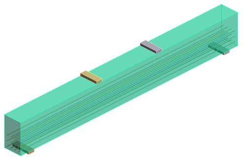
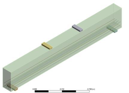
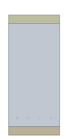
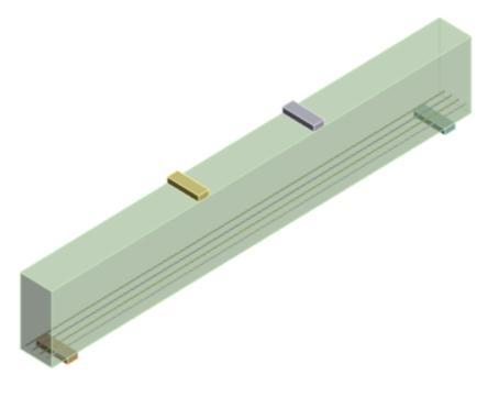
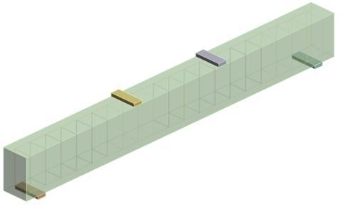
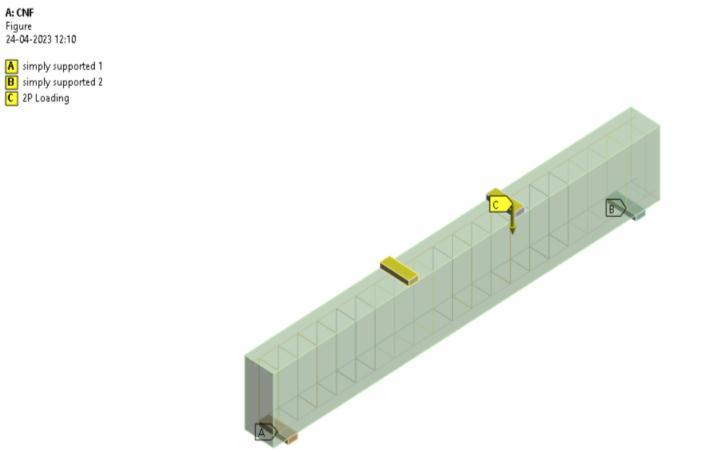
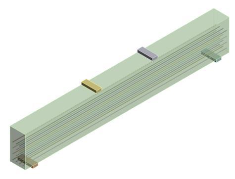
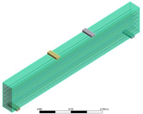
Thesimulatedbeamshavedimensionsof150mminwidth, 300mmindepth,and2minlength.The3DPCbeamsuse highstrengthgalvanizedwiresasreinforcement.Theseare constructedfromtwo2.5mmdiameter,1150N/mm2strong twistedlinewires.
Wearenowconstructing10versionsof3DPCbeamswith various configurations of high strength wires serving as reinforcement. Results are achieved by comparing these modelstoatraditionalRCCbeam.





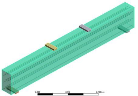

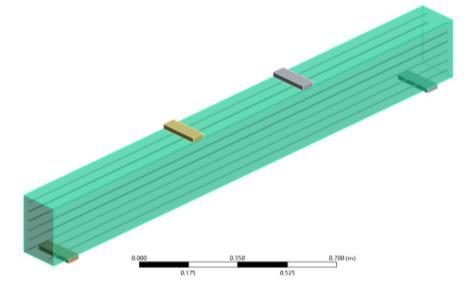

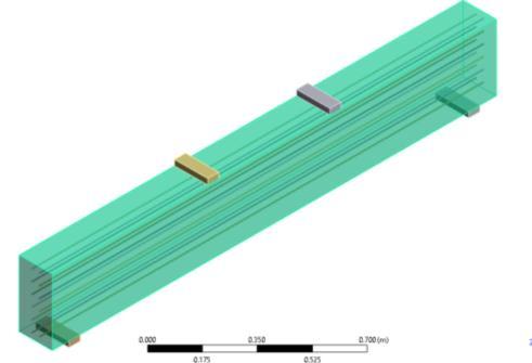



2.1 Analysis

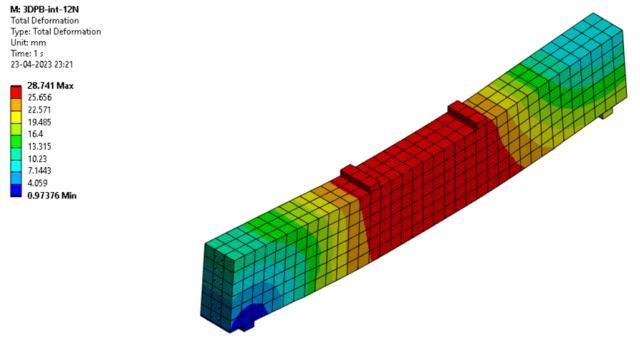
In ANSYS software, nonlinear static structural analysis is performed. Studies are done on deformation and load carrying capacity. The following figures display the deformationdiagrams.
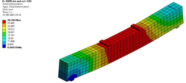
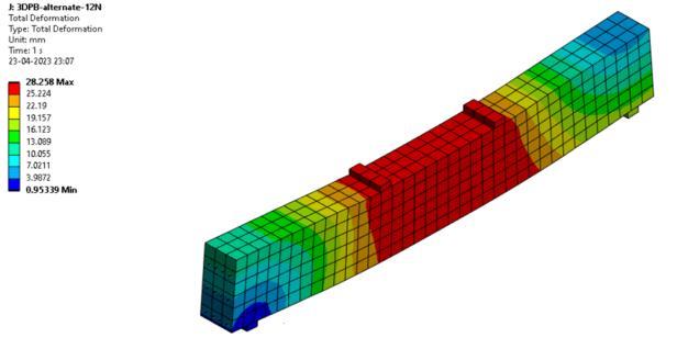
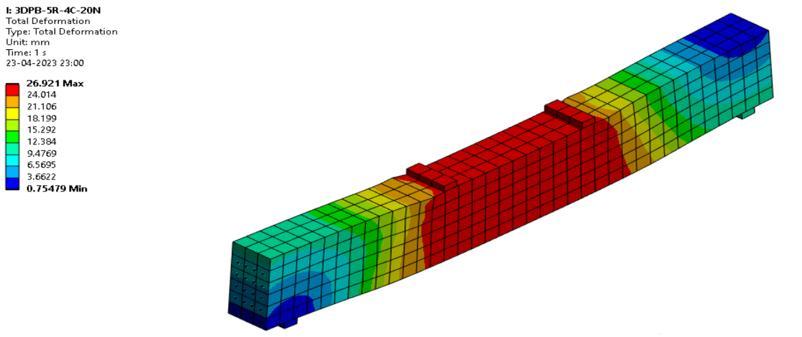


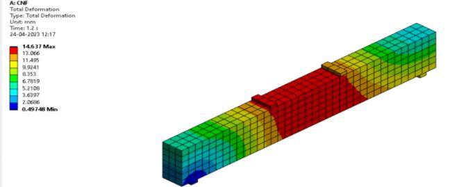
2.2 Result and discussion
The result obtained from the analysis of internally strengthened3DPCbeamsarecomparedwithconventional beamForthatloaddeformationcurveistakenforeachmodel. Thegraphicalrepresentationofloadanddeflectionofbeams areshown.



Thefourthmodel's3DPBhasalargerloadcarryingcapacity thana typical beam. It'spossiblethat3DPB -4R -4C -16N performs better than standard beam. Thus, Model 4 with fourrowsofstrengtheningwiresisselected.
3. Performance of externally strengthened 3DPC beams with varying bolt arrangement
The various bolt arrangement patterns holding the steel plates are analyzed in this chapter to find the best configuration. External strengthening of 3DPC beams are donebyprovidingsteelplatesonbothsidesofbeam These

plates are held together by bolt type arrangement. In this chapter6differentmodelsofexternallystrengthenedbeams areanalyzedbyvaryingtheboltarrangementpattern.Plate thicknessof3mmischosen
3.1 Analysis
SoftwarecalledANSYSisusedtoperformstructuralanalysis. Beam deformation and load carrying capability are determined.
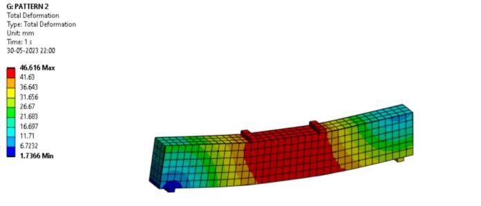

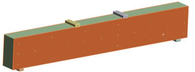
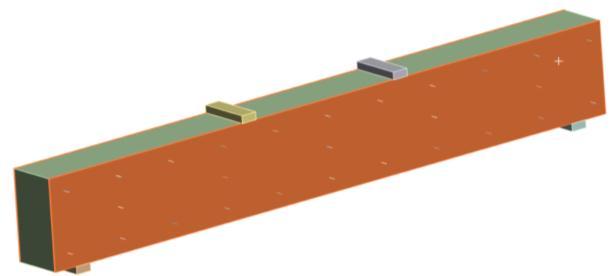
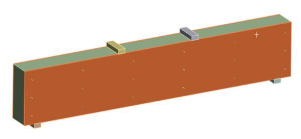

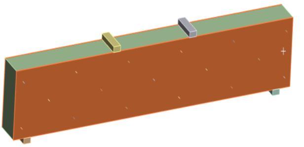
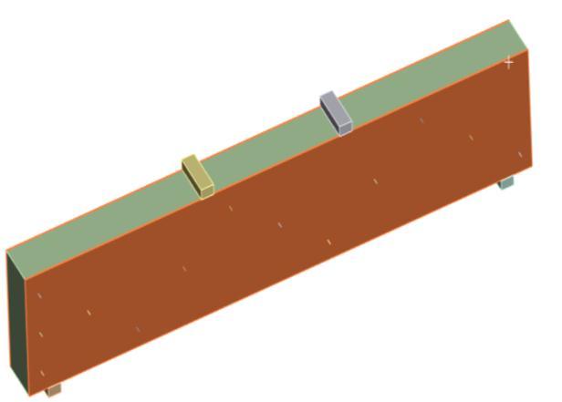

Chart -2: comparison graph
Table – 2: comparison table
By adding steel plates on both sides of the beam, 3DPC beams are externally strengthened. These plates are connected by a bolt arrangement. The bolt arrangement pattern is changed to assess six alternative models of externallystrengthenedbeamsinthischapter.3mmthick platesareselected
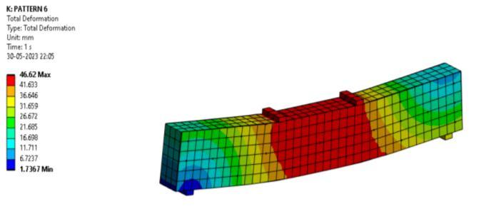
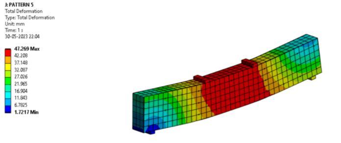
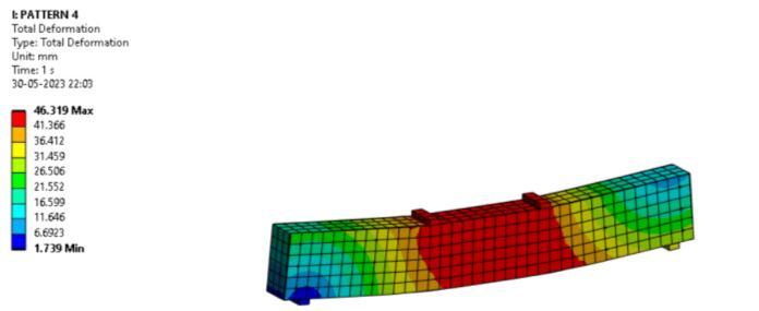
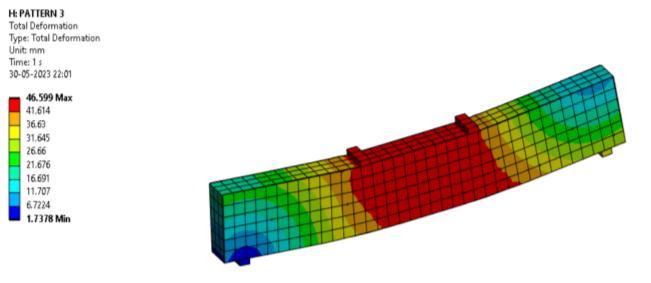
Steel plates are added to both sides of 3DPC beams to strengthentheirexteriors.Theboltarrangementthatholds these plates together. By changing the bolt arrangement pattern,sixdistincttypesofexternallystrengthenedbeams areexaminedinthischapter.A3mmplatethicknessisused. The load-deflection graph of the six different bolt arrangementpatternsisexamined,andpattern4isselected.
4. CONCLUSIONS

High strength galvanized wires are used for internal strengthening. By comparing 10 distinct strengthened models toa standard beam model, the % improvement in loadcarryingcapacitywasdetermined.Thefourthmodel's 3DPB has a larger weight carrying capacity than a typical beam.It'spossiblethat3DPB-4R-4C-16Nperformsbetter than standard beam. Thus, Model 4 with four rows of strengthening wires is selected. Steel plates are added to bothsidesof3DPCbeamstostrengthentheirexteriors.The bolt arrangement that holds these plates together. By changingtheplatethickness,fourdistincttypesofexternally strengthened beams are examined. The available plate

thicknesses are 3mm, 2.5mm, 2mm, and 1.5mm. Plate thicknessisdeterminedtobe3mmafterevaluationofthe load deflection curves. By changing the bolt arrangement pattern,sixdistincttypesofexternallystrengthenedbeams are examined. A 3 mm plate thickness is used. The loaddeflection graph of the six different bolt arrangement patterns is examined, and pattern 4 is selected. Thus, 16 numberofbolttypearrangementswillhold3mmplatesfor externalbeamstrengtheningpurposesoneithersideofthe beam.
REFERENCES
[1] XiaoyuHana,b,c,JiachuanYana,b,c,*,MingjianLiua,b,c, LiangHuod,JunlinLia,b(2022)Experimentalstudyon large-scale 3D printed concrete walls under axial compression
[2] A.V.Rahul,M.Santhanam,H.Meena(2019)Mechanical characterizationof3Dprintableconcrete
[3] M.Claen,J.Ungermann,R.Sharma(2020)Additive manufacturingofreinforcedconcrete-developmentof a3DprintingTechnologyforCementitious Compositeswithmetallicreinforcement
[4] B.Nematollahi,P.Vijay,J.Sanjayan,A.Nazari,M.Xia,V. Naidu Nerella, V. Mechtcherine (2018) Effect of polypropylene fibre addition on properties of Geopolymers made by 3D printing for digital Construction.
[5] J.Putten,G.D.Schutter,K.V.Tittelboon(2019)Surface modification as a technique to improve inter-layer bondingstrengthin3Dprintedcementitiousmaterials

