THREE-PHASE OF BI-DIRECTIONAL Z-SOURCE CONVERTERS FOR VEHICLE-TO-GRID APPLICATIONS A LOW-HARMONIC AND FUZZY LOGIC
CONTROL METHOD
Mr. Mamindla. Shyamprasad1 , Dr. M. Saravanan2
1PG Scholar in electrical power systems department of electrical and electronics engineering at Holy Mary Institute of Technology and Science, Bogaram, Medchal Dist, Hyderabad, India.
2Professor of electrical and electronics engineering at Holy Mary Institute of Technology and Science, Bogaram, Medchal Dist, Hyderabad, India.

Abstract - This paper presents the plan of shut circle regulators working a solitary stage AC-DC three-level converterforfurtherdevelopingpowerqualityatACmains. Shutcirclerestrainsexternalvoltageregulatorandinward current regulator. Reproductions of three level converter withthreeuniquevoltageandcurrentregulatormixes,for example, PI-fluffy Rationale control are completed in MATLAB/Simulink.Executionboundaries,forexample,input power variable and source current Total Harmonic Distortion(THD)areconsideredforexaminationofthethree regulatormixes.ThefluffytunedPIvoltageregulatorwith hysteresis current regulator blend gives an improved outcome,withasource-currentTHDof0.93%andsolidarity powerfactorwithnosourcesidechannelforthethreelevel converter.Forloadvarietiesof25%to100percent,aTHDof under5%isgottenwithamostextremeworthofjust1.67%. Atlast,thefluffytunedPIvoltage.Asource-currentTHDof 1.351% is gotten in the exploratory review with a power factor close to solidarity. In this paper, three new balance plansforthree-stageZ-sourceconvertersareproposedand explored.Thebestperformedoneisadditionallyevolvedto ashutcirclefluffycontrolstrategy.Whilethevoltagechange proportionisadaptable,theresultvoltageAbsoluteSounds Bending(THD)isbeneath3%insidethevoltageproportion scopeof0.5to2.5.Theadequacyoftheproposedstrategy has been completely approved in MATLAB/Simulink reproductionsContrastedwithexistingcontroltechniques, theproposedone performs betterwithdiminishedmusic, adaptable voltage gain, and more straightforward control algorithm
Key Words: Z-source converter, Bi-directional converter, shoot-throughstates,voltageharmonics,closed-loopclosedloop,fuzzycontrolmethod
1. INTRODUCTION
ShapeimpedancenetworkcomposedoftwoinductorsLZ1, LZ2andtwocapacitorsCZ1,CZ2iscombinedinatraditional threephasefull-bridgeinverter[6].Becauseoftheexistence oftheX-shapeimpedancenetwork,itispossibletoturnon thetwononebridgesimultaneouslywithoutshort-circuited the input voltage source [4]. Moreover, the Z-source
inverters take advantage of the shoot-through states ingeniously to achieve voltage boosting without any additionalswitchesorcontrolcircuitry[7].Therefore,theZsourceinverterscouldachievevoltagebuckandboostingby asingle-stagetopologywithhighrobust.Thevoltagelevelof differentmicrogridscouldvaryconsiderably,whichmakes theZ-sourceconvertersmoreadvantageousintheprocessof EVbatteries’feedingto
The grids. The Z-source inverter could also operate bidirectional, which is essential in V2G applications. The input diode Dr is connected in parallel with a switch S1. When switch S1 is turned on, the Z-source inverter could operate as a conventional three-phase PWM rectifier. Because of the above-mentioned features, Z-source converters have been widely investigated in areas of not onlyEVcharging[8][9],butalsoEVmotordrive[10][11], PVsolarenergysystem[12][13],wirelessenergytransfer [14] [15] and integration of microgrid [16] [17]. The increasingvoltagegaincapabilityandmodulationindexesof bothrectifierand inverterstagesareadvantagesofthreephase Z-source converters [18]. Different approaches of applying bi-directional Z-source inverters in V2G applications have been investigated [19] [20]. Paper [21] providedanoverallintroductionandcomparisonofspace vector modulation schemes for three-phase Z-source inverters.Besidesthe basic Z-sourceimpedance topology, many modified Z-source topologies have been developed [22]- [24] to reduce switching loss and improve power density. Though these proposed converters based on Zsource topology could generally achieve smaller size and wider voltage conversion ratio, they have issues in complicatedstructure,instability,voltagestressofswitches, powerlevellimitation[24]andoutputharmonics[7][25]. Therefore,
Thispaperaimstoimprovetheperformanceofconverterby designing and optimizing the control method of a basic three-phase Z-source converter, rather than adding more devices or complicated circuits. India has relatively long sunnydaysformorethantenmonthsandpartlycloudysky formostofthedaysi.e.almosttwomonths.ThismakesIndia very rich in solar energy especially desert sides in west
which include Gujarat, Rajasthan, Madhya Pradesh etc. Photovoltaic Panel or modules are used directly to create electricity.Besidesthissolarpanelshowever,italsoneeds “BalanceofSystem”componentsincludinginverters,wiring, breakersandswitches,whichcanaccountforuptohalfof the system cost. Inverters like string inverters, microinverters are used with PV panels. In string inverters the severalnumbersofpanelsareconnectedinserieswithone centralized inverter, while micro-inverter invert the electricityfromsinglePVpanel,aseachpanelhasasingle inverterattachedbeyondit.Micro-inverterisanupcoming fieldofresearchinPVtechnologyasithasmoreadvantage overotherPVsystems.Itisusedasplugandplaydevices. Typically,themicroinverteraredesignforlowerranges;as the capacity of solar panel increases, the size of microinverter should increases as well[1,2]. In this paper the simulation of micro-inverter is discussed with analysis of control techniques of it Global temperature changes have becomeamajorprobleminglobalwarminginrecentyears. Inadditiontoenergydemand,thereisalsoanenvironmental threats.Manycountriesareconcernedtoreducetheirozonedamagingemissionsandtocontinuetheireffortstoimprove theenergysystem.Renewableenergysourcesseehowthese problems are solved. In 2017, an estimated 17 countries generatedmorethan90%oftheirelectricityfromrenewable sources[1].Solarenergyisconsideredtobeoneofthemost importantrenewablesourcesavailableinabundance,freeof pollutionandfreeofchargeinremoteareaswherethereis stillnoelectricity.[2]-[3].

Solar power extracted from solar photovoltaic (PV) cells deliverslowefficiency[4].Becauseoftheseproblems,itis important to extract maximum power from solar photovoltaic cells and improve efficiency in different weatherandtemperatureconditions.AnMPPTorMaximum PowerPointTrackingisanelectronictrackingdeviceusually digitalDCtoDCconverterwhichisconnectedbetweensolar panels and battery or the utility grid that optimizes the matchbetweenthesolararray(PVpanels),andthebattery bank or utility grid. It monitors the PV array for the maximumpowerpointandtriestousethisinformationnot only to control the output Typically, this means that the voltageisreducedwhilethecurrentisincreasedandmostof theoverall
2. CLOSED-LOOP CONTROL METHOD
Open-loopsimulationsarepresentedabovewhere M and B areconstant.Toachieveclosed-loopcontrol, M and B shall becalculatedaccordingtothemeasuredoutputvoltagevia PI control in real-time to ensure that the output voltage magnitude would follow the reference. The dynamic response design process is the same as the one of conventionalPIcontrol.Theclosed-loopcontroldiagramof switchingsignalsgenerationispresentedasshowninFig.1
Twoclosed-loopsimulationsareconducted.First, thereferencevoltagehasastepchangefrom750Vto900V (r.m.s.),i.e.thepeakvoltagechangesfrom1060Vto1273V. Fig. 1 shows that the balanced three phase voltages increasedtothenewreferencesmoothlywithineightcycles, which takes 0.16s. Secondly, the resistance Rload of each resistive load in star connection switches from 112.5Ω to 200Ω.AsshowninFig.2,atthemomentofloadchangewhen t=0.5s,theoutputvoltageincreasesforashorttimebecause of the disturbance in load resistance. Then the output voltage is soon regulated and reduced to the rated value 1060V.Theoutputvoltageandcurrentbecomestablewithin twocycles.Thedesignofthisclosed-loopcontrolisbasedon applying the new sine variable modulation scheme to the traditionalclosed-loopSPWMPIcontrolmethods.Thereis nomodificationinthetopologyofthethree-phaseZ-source inverter.ThecommoncontrolvariableofZ-sourceinverters istheshoot-throughdutyratio D,whichisequalto6B/πin the proposed modulation schemes. The common output variable of the closed-loop control design is the capacitor voltage VCZ1 Fig.13Simulationwaveformswhenreference voltage changes Fig.14 Simulation waveforms of output phasevoltagesandcurrentswhenRloadchanges(equalto VCZ2), which directly determines VZ and output voltage magnitude. Therefore, the methodology of small signal analysis,transferfunctionanddynamicresponsedesignby bodeplotoftypicalthree-phaseZ-sourceinverterscouldbe directlyadoptedintheproposedmodulationscheme. The
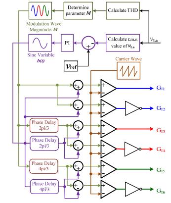
proposed control could also be easily modified for the operation ingrid-connected mode.Inconventional SPWM controlmethodsofgrid-connectedthree-phasefull-bridge inverters,themagnitudeofmodulationwavesisderivedfor generatingswitchingsignals[38].Thevaluesofparameter M and B could be obtained based on the value of Sabc Parameters mAu, mAl, mBu, mBl, mCu, mCl are thus obtained which represent the magnitudes of modified corresponding modulation waves to insert shoot-through states. The main characteristics of conventional control methodsaremaintained.Itisassumedthatthethreeoutput phase voltages or three-phase loads are balanced in this paper,thusonlyphasevoltage vLa is being measuredand calculatedfortheclosed-loopcontrolasshowninFig.12.If thereisavoltageorloadunbalance,onlyphasevoltage vLa couldcatchthereferencewhiletheothertwophasevoltages would vary. Therefore, the proposed closed-loop control method works the best when there is no voltage unbalancepresentintheconnectionpointtothegrid.Input voltagesothattheoutput(load)ishigherthantheinput[6] Implementation of Boost Converter Fig.9.Boost converter circuit containing an inductor, a transistor, a diode, and a capacitor.Theconnectionofthetransistorbehavessimilarly toaswitchwhichcanturnonoroffbycontrollingtransistor gatevoltage.IfweclosetheswitchDCvoltageappearsacross theinductorandcontinueincreasingsolongastheswitchis closed. The current through an inductor cannot change instantaneously [7] therefore the moment we open the switchtheinductorwillcreateaforcecausingthecurrentto continueflowingtowardsoutputcircuit


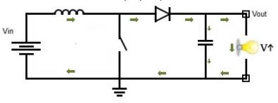


ii.Switchoff(0%dutycycle)Ifweleavetheswitchturnoff 100%ofthetime,theoutputvoltagewillequaltothebattery voltage.
DC output
Switchon(100%dutycycle)Ifweleavetheswitchalways on 100% of the time, the current will theoretically keep increasingtoinfinityandovercurrentflowcangeneratean excessamountofheatwhichcancausedamagetheentire circuit
SIMULATION RESULTS
TheDCsidevoltage Vdc issetas500Vtorepresentatypical EV battery voltage. The balanced three-phase loads are composed of three resistors whose resistance Rload is 112.5Ω in star connection, LZ1=LZ2=280µH, CZ1=CZ2=141µF,Lf=8.95mH,Cf=7µF,ACoutputfrequency f=50Hz.Thecalculationoftheseparametersispresentedin theAppendix.
Thepeakmagnitudeofratedoutputphasevoltageissetas 1060V, whose r.m.s. value is 750V at the medium voltage level. Fig. 8 shows the waveforms of three output phase voltages vLa, vLb and vLc respectively. The THD of each phasevoltageisonly2.66%.

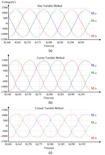
To further investigate the difference among the three methods on output voltage harmonics, open-loop simulations have been conducted with M=0.9 and B=0.25 such that the magnitude of modified modulation waves wouldgobeyondthemagnitudeofthecarrierwaveandthe outputharmonicswouldincreaseundoubtedly.Inthisway, theeffectofthethreecontrolmethodsonoutputharmonics could be clearly illustrated. Waveforms of output phase voltagesarepresentedinFig.9.Itisclearthatwithsucha largevalueof B,theoutputharmonicofsinevariablemethod stillmaintainswithinalowlevel.Incontrast,theharmonics ofcosinevariablemethodismuchgreater.Theharmonics levelofconstantvariablemethodisslightlylowerthanone of cosine variable method, but the voltage magnitude is lowerthanexpected.

Thisisbecausethetotaldurationoftheshoot-throughstates in a three-phase topology has become too long, and the averagemagnitudeofboththecapacitorvoltage VCZ1, VCZ2 andvoltage VZ couldnotreachtheidealvaluesin(3).The harmonicanalysisplotsofthreemethodsareshowninFig. 10. The cosine variable method produces the highest 5th order harmonics. The 5th, 7th and 11th order harmonics accountformostofthetotalharmonicsinthethreemethods, while there is little even order harmonics because of the

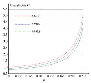
symmetricityofthecontrollogic.Fig.11(a)representsthe relationship between the THD of phase voltage VLa and parameter B when M=0.9.Asthemagnitudeandfrequency ofoutputphasevoltage VLa arethesameas VLb and VLc, only VLa ispresentedasarepresentative.
Cosinevariablemethodhasthegreatestoutputharmonics, while sine variable method leads to lowest output harmonics.Forsinevariablemethod,thetotalTHDofoutput phasevoltage VLa isonly2.83%when B=0.2,whichmeans the magnitude of the modified modulation wave already exceedsthemagnitudeofthecarrierwave.Sincetheoutput loadisresistive,thevoltagedistortionandcurrentdistortion are the same. For reference, the harmonics of 2nd – 19th orders are compared with the limits in the IEEE 1547 standard[37]asshowninredinFig.10(d).Itisclearthat theoutputharmonicsarewellbelowharmoniclimitsofthe IEEE1547standard.
Fig.11Waveformsofoutputphasevoltageswithhigh shoot-throughdutyratio D:(a)Sinevariablemethod;(b) Cosinevariablemethod;(c)Constantvariablemethod
CONCLUSION

This paper presents the design of closed loop controllers operating a single-phase AC-DC three-level converter for improvingpowerqualityatACmains.Closedloopinhibits outer voltage controller and inner current controller. Simulations of three level converter with three different voltage and current controller combinations such as PIfuzzy Logic control are carried out in MATLAB/Simulink. Performance parameters such as input power factor and source current total harmonic distortion (THD) are considered for comparison of the three controller combinations. The fuzzy-tuned PI voltage controller with hysteresiscurrentcontrollercombinationprovidesabetter result,withasource-currentTHDof0.93%andunitypower factor without any source side filter for the three level converter.Forloadvariationsof25%to100%,aTHDofless than5%isobtainedwithamaximumvalueofonly1.67%. Finally,thefuzzy-tunedPIvoltage.Asource-currentTHDof 1.351%isobtainedintheexperimentalstudywithapower factor near unity in this paper, three new modulation schemesforthree-phaseZ-sourceconvertersareproposed and investigated. The best performed one is further developedtoaclosed-loopfuzzycontrolmethod.Whilethe voltageconversionratioisflexible,theoutputvoltageTotal HarmonicsDistortion(THD)isbelow3%withinthevoltage ratiorangeof0.5to2.5.Theeffectivenessoftheproposed method has been fully validated in MATLAB/Simulink


simulations Transient waveforms showed the dynamic response with the disturbance of input voltage and load resistance. The output phase voltages could catch the reference quickly and smoothly. Compared to existing controlmethods,theproposedonehasbetterperformance on harmonics suppression with an uncomplicated control algorithm, thus would be suitable for its application in vehiclechargerswithbi-directionalpowerflowbetweenthe vehiclebatteriesandthethree-phaseACbusofamicrogrid. Thefutureworkmainlyincludestheimplementationofan EV charger prototype to testify the charging performance and conversion efficiency in a Power Hardware-In-Loop (PHIL) testing platform, suppression of the input current spikesandtheadvancedcontrolinunbalancedloadcases.
REFERENCES
[1]S.A.Singh,G.Carli,N.A.AzeezandS.S.Williamson,"A modified Zsource converter based single phase PV/grid inter-connected DC charging converter for future transportationelectrification," 2016 IEEE Energy Conversion Congress and Exposition (ECCE),Milwaukee,WI,2016,pp.
[2] Yushan Liu, Haitham Abu-rub, Gaoming Ge, “Z-Source QuasiZSourceInvertersDerivedNetworkdsModulations”, IEEE Industrial Electronics Magazine,Dec2014
[3]S.Jain,M.B.ShadmandandR.S.Balog,"DecoupledActive andReactivePowerPredictiveControlforPVApplications UsingaGrid-TiedQuasi-Z-SourceInverter," IEEE Journal of Emerging and Selected Topics in Power Electronics,vol.6,no. 4,pp.1769-1782,Dec.2018.
[4]FangZhengPeng,"Z-sourceinverter," IEEE Transactions on Industry Applications,vol.39,no.2,pp.504-510,MarchApril2003.
[5]MiaosenShen,JinWang,A.Joseph,FangZhengPeng,L.M. Tolbert and D. J. Adams, "Constant boost control of the Zsource inverter to minimize current ripple and voltage stress," IEEE Transactions on Industry Applications,vol.42, no.3,pp.770-778,May-June2006.
[6]Y.Liu,H.Abu-Rub,Y.XueandF.Tao,"ADiscrete-Time Average Model-Based Predictive Control for a Quasi-ZSourceInverter," IEEE Transactions on Industrial Electronics, vol.65,no.8,pp.6044-6054,Aug.2018.
[7]Q.Zhang,T.Na,L.SongandS.Dong,"ANovelModulation for SoftSwitching Three-Phase Quasi-Z-Source Rectifier WithoutAuxiliaryCircuit," IEEE Transactions on Industrial Electronics,vol.65,no.6,pp.5157-5166,Jun.2018.
[8] Guo Feng, Fu Lixing, Lin, Chien Hui, Li Cong, Choi Woongchul, Wang Jin, "Development of an 85-kW Bidirectional Quasi-Z-Source Inverter With DC-Link FeedForward Compensation for Electric Vehicle Applications",
IEEE Transactions on Power Electronics,vol.28,no.12,pp. 5477-5488.Dec2013
[9]TuopuNa,QianfanZhang,JiaqiTang,and Jinxin Wang, "Active Power Filter for Single-Phase Quasi-Z-Source IntegratedOn-BoardCharger", CPSS Transactions on Power Electronics and Applications, vol. 3, no. 3, Sep 2018
[10]AlexandreBattiston,El-HadjMiliani,SergePierfederici, and Farid Meibody-Tabar, "Efficiency Improvement of a Quasi-Z-Source InverterFed Permanent-Magnet Synchronous Machine-Based Electric Vehicle," IEEE Transactions on Transportation Electrification,vol.2,no.1, pp.14-23,2016.
[11]JérémyCuenot,SamiZaim,BabakNahid-Mobarakeh,et al,"OverallSizeOptimizationofaHigh-SpeedStarterUsinga Quasi-Z-Source Inverter," IEEE Transactions on Transportation Electrification,vol.3,no.4,pp.891-900,Dec 2017.
[12] Y. Li, S. Jiang, J. G. Cintron-Rivera and F. Z. Peng, "Modeling and Control of Quasi-Z-Source Inverter for DistributedGenerationApplications," IEEE Transactions on Industrial Electronics, vol. 60, no. 4, pp. 1532-1541, April 2013.

[13]W.Liang,Y.Liu,B.Ge,H.Abu-Rub,R.S.BalogandY.Xue, "DoubleLine-Frequency Ripple Model, Analysis, and ImpedanceDesignforEnergy-StoredSingle-PhaseQuasi-Z SourcePhotovoltaicSystem," IEEE Transactions on Industrial Electronics, vol. 65, no. 4, pp. 3198-3209, April 2018.
[14]H.Zeng,X.WangandF.Z.Peng,"HighpowerdensityZsource resonant wireless charger with line frequency sinusoidalcharging," 2017 IEEE Energy Conversion Congress and Exposition (ECCE),Cincinnati,OH,2017,pp.2773-2778
AUTHOR DETAILS
Mr. Mamindla. Shyamprasad receivedaB.techinelectrical andelectronicsengineeringfromTudiRamReddyInstitute ofEngineeringandTechnology(TRRIT),Bibinagar,Nalgonda Dist.AndstudyingM.techinelectricalpowersystemsatHoly MaryInstituteofTechnologyandScience,Bogaram,Medchal Dist,Hyderabad,Indiainthedept.electricalandelectronics engineering.

Dr. M. Saravanan received a B.E. in Electrical and ElectronicsEngineeringfromSriSairamEngineeringCollege, WestThambaramin2004andM.Tech.inPowerElectronics &DrivesfromtheCollegeofEngineering,Guindyin2010, and a Ph.D. degree in Electrical Engineering from Anna University, Chennai in 2018. He is currently working as a ProfessorofDept.ofElectrical&ElectronicsEngineeringat HolyMaryInstituteofTechnologyandScience,Hyderabad


