DC MICROGRID USING PHOTOVOLTAIC IMPROVED INCREMENTAL CONDUCTANCE ALGORITHM FOR TRACKING THE MPP IN A STANDALONE MINIMIZING ENERGY STORAGE UTILIZATION
Mr. Mandli Vamshidhar Reddy1 , Dr.Sivaganesan Sivanantham21PG Scholar in electrical power systems department of electrical and electronics engineering at Holy Mary Institute of Technology and Science, Bogaram, Medchal Dist, Hyderabad, India.
2Professor of electrical and electronics engineering at Holy Mary Institute of Technology and Science, Bogaram, Medchal Dist, Hyderabad, India. ***

Abstract - This paper proposes a versatile and ideal control procedure for a sunlight based photovoltaic (PV) framework.Thecontrolprocedureguaranteesthatthesun basedPVboardisgenerallyoppositetodaylightandallthe while worked at its most extreme power point (MPP) for constantly reaping greatest power. A mixture control techniqueforaPVandbatteryenergycapacityframework (BESS)inanindependentdcMGisproposedinthispaper. Rather than the traditional control methodologies that manage the dc-interface voltage just with the BESS, the proposedcontrolproceduretakesadvantageofboththePV framework and the BESS to direct the dc-connect voltage. The proposed control methodology is the control blend betweenthesolarpoweredtrackers(ST)and(MPPT)that can enormously work on the produced power from sun based PV frameworks. As to ST framework, the paper presentstwodriveapproachesincludingshutcircledrives. ThepaperlikewiseproposesIncrementalconductance(InC) calculationforimprovingthespeedoftheMPPfollowingofa sun oriented PV board under different climatic circumstances as well as ensuring that the working point generally moves towards the MPP utilizing this proposed calculation. The viability of the proposed control methodology on delayingthelifetime ofa lithium-particle batteryandalead-corrosivebatteryisexaminedthrougha reenactmentcontextualinvestigationwithone-dayburden andirradiancebendprofiles
Key Words: Batteryenergystoragesystem(BESS),battery state-of-charge (SoC), dc microgrid (dc MG), improved incremental conductance power point tracking (InCPPT) algorithmphotovoltaic(PV).
1. INTRODUCTION
Energyisabsolutelyessentialforourlifeanddemandhas greatlyincreasedworldwideinrecentyears.Theresearch effortsinmovingtowardsrenewableenergycansolvethese issues.Comparedtoconventionalfossilfuelenergysources, renewable energy sources have the following major advantages:theyaresustainable,nevergoingtorunout,free and non-polluting. Renewable energy is the energy
generatedfromrenewablenaturalresourcessuchassolar irradiation, wind, tides, wave, etc. Amongst them, solar energyisbecomingmorepopularinavarietyofapplications relating to heat, light and electricity. It is particularly attractivebecauseofitsabundance,renewability,cleanliness and its environmentally-friendly nature. One of the importanttechnologiesofsolarenergyisphotovoltaic(PV) technologywhichconvertsirradiationdirectlytoelectricity bythePVeffect.However,itcanberealizedthatthesolarPV panels have a few disadvantages such as low conversion efficiency (9% to 17%) and effects of various weather conditions [1]. In order to overcome these issues, the materials used in solar panel manufacturing as well as collectionapproachesneedtobeimproved.Obviously,itis particularlydifficulttomakeconsiderableimprovementsin thematerialsusedinthesolarPVpanels.
Renewable energy resources are rapidly replacing conventionalfuelstogenerateelectricityinordertoachieve energysustainability,andreducethecarbonfootprint[1]. Solar energy is one of the most abundantly available renewable resources and hence, photovoltaic (PV) power generationshareissteadilyincreasing.DCmicrogrid(dcMG) powersystemsaredrawinggreatattentionduetothesteady growthin dcloaddemandandrenewable dcsources.The majority of modern consumer electronics such as energyefficientlightingsystemsandenergy-savingelectronicsare operated with dc supply. Furthermore, PV modules and batteries are intrinsically dc components. Therefore, by usingadcMGtotransferpowerfromdcsourcestodcloads wouldeliminatethenecessityofhavingdc-to-acconversion stagesonthegenerationsideandac-to-dcconversionstages ontheloadside.Also,synchronizationandreactivepower flowissuesarenullindcMGs[2],[3].Suchdcsystemsare used in a broad range of applications including ships, automobiles, telecommunication stations, etc. However, issues associated with dynamically changing weather conditions and dc-link voltage transients may lead to instability in the microgrid and hence, dcMGs require a robust control scheme. The majority of existing PV controllersaimtoextractthemaximumpowerfromthePV arrays using maximum power point tracking (MPPT)
algorithms[4],[5],andthe batteryenergystoragesystem (BESS)dealswiththepowerdifferencebetweentheloadand the PV generation. Nowadays, with falling PV energy cost, supersizing the PVcapacity justfor thepurposeofhaving more PV energy during the afternoon hours is a common practiceandmakesperfecteconomic senseinmanycases [6], [7], [8], [9]. As the PV capacity increases, its effect on grid parameters will increase as well. Therefore, the PV system should play a bigger role by participating in grid stabilization. When the PV capacity increases, MPPT operation may cause dc-link over-voltage and the BESS overcharging issues. Hence, the MPPT method alone is insufficient to control the PV generation and additional featuresareneededtohelpmaintainthedc-linkvoltage[6]. The excessive PV penetration issue is solved with MPPT droopdual-modecontrolstrategywiththeBESS[10],[11], [12],[13].However,thecontrollerforthePVgeneration
Therefore, increasing of the irradiation intensity receivedfromthesunisanattainablesolutionforimproving the performance of the solar PV panels. One of the major approaches for maximizing power extraction in solar PV systemsisasuntrackingsystem.Thesuntrackingsystems wereintroducedin[2]-[3]usingamicroprocessor,andin[4] using a programmable logic controller respectively. The closed-loopcontrolschemesforautomaticsuntrackingof double-axis, horizon single-axis, and fixed systems were presented and compared in [5]. Furthermore, the idea of designingandoptimizinga solartrackingmechanism was alsoproposedin[6].Additionally,itcanalsoberealizedthat theV-Icharacteristicofthesolarcellisnon-linearandvaries withirradiationandtemperature[1].Generally,there isa unique point on the V-I or V-P curve which is called the MaximumPowerPoint(MPP).ThismeansthatthesolarPV

panelwilloperatewithamaximumefficiencyandproducea maximumoutputpower.TheMPPisnotknownontheV-Ior V-Pcurve,anditcanbelocatedbysearchalgorithmssuchas thePerturbationandObservation(P&O)algorithms[7]-[12], theIncrementalConductance(InC)algorithm[13]-[14],the Constant Voltage (CV) algorithm [15]-[16], the Artificial NeuralNetwork(ANN)algorithm[17]-[18],theFuzzyLogic (FL) algorithm [19]-[20], and the Particle Swarm Optimization (PSO) algorithm [21]-[24]. These existing algorithms have several advantages and disadvantages concerned with simplicity, convergence speed, extrahardware and cost. This paper proposes an improved InC algorithmfortrackingaMPPontheV-Icharacteristicofthe solarPVpanel.BasedontheSTandMPPT,thesolarPVpanel isalwaysguaranteedtooperateinanadaptiveandoptimal situationforallconditions.Theremainderofthispaperis organizedasfollows.
ThemathematicalmodelofsolarPVpanelsisdescribedin Section II. A proposal for adaptive and optimal control strategyofasolarPVpanelbasedonthecontrolcombination ofthesolartracker(ST)andMPPtracker(MPPT)withthe improved InC algorithm is presented in Section III. The simulationandexperimentalresultsthenfollowtoconfirm thevalidityoftheproposalinSectionsIVandV.Finally,the advantages of the proposal are summarized through a comparison with other solar PV panels. Development and Comparison of an Improved Incremental Conductance AlgorithmforTrackingtheMPPofaSolarPVPanel.
2. CIRCUIT CONFIGURATION
In[10]generatesdisturbancesonthedc-linkvoltageduring operationmodetransitionsandthetransitioncriteriaitself complicatesthecontrolalgorithm.ThePVcontrollerin[11] only focuses on the dc-link voltage regulation, and the algorithmin[12]onlyfocusesontheMPPToperationmode.
Therefore,anadditionalouter-loopcontrollerisrequiredto extract the maximum power from the PV in [11], and to regulate the dc-link voltage in [12]. An MPPT and droop integratedcontrolmethodisintroducedin[13]toeliminate the system disturbances by avoiding the control
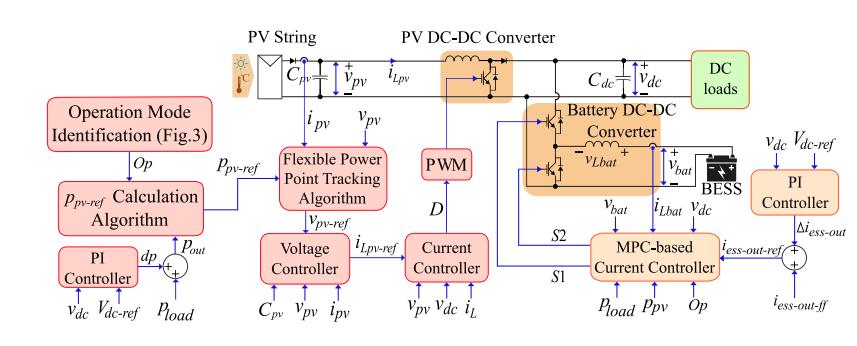
reconfiguration during operation mode transitions. The droopcontrollerregulatoristhekeyelementinthecontrol that provides a duty ratio for the dc-dc converter by calculatingtherequiredchangeofthepowerwiththedroop coefficient.However,thePVcontrollersin[10],[11],[12], [13]operatewiththeconstantvoltage-steptoadjustthePV generation,resultingaslowdynamicresponseunderrapid environmentalchanges.Hence,thebatteryistheprimarydclink voltage controller and operates continuously (charge/discharge) to effectively regulate the dc voltage fluctuations,whicharemainlyimposedbytheloaddemand transients and the intermittent irradiance changes. Such aggressiveutilizationseverelydegradesthebatterylifetime [14],[15].
The proposed control techniques for dcMGs in [16], [17], [18]didnotconsiderreducingthebatteryutilizationandthe excessiveuseofbatterypowertoregulatethedc-linkvoltage isadrawbackthatdrasticallyshortensthebatterylifetime. Furthermore, the forecast-based control proposed in [19] limits the state-of-charge (SoC) to an estimated SoC reference, which is predicted based on the load demand patterns, to prolong the battery lifetime. However, the controlinvolveswiththeonlinecommunicationplatformfor the forecasting data and it is only effective in the gridconnected system since it limits the battery charging capacity.Inthestand-alonedcMGsystem,thebatteryisthe only available backup source when the PV generation is absentandhence,theSoCneedstobekepthigh.Tosolvethe abovementioneddrawbacks,thispaperproposesacontrol strategyforastand-alonedcMGsystemwithPVandBESS.In theproposedhybridcontrolstrategy,thePVsystemisthe primary dc-link voltage regulator and the BESS acts as a secondary dc voltage control asset that can remain in standbymodeaslongasthePVisableto maintainthe dc voltagewithinadesiredrangeandthebatterydoesnotneed tocharge.Thiscontrolhierarchy,thusprolongsthebattery lifetimebyminimizingtheutilizationoftheBESS.
TheproposedcontrolstrategykeepstheSoCofthebattery withinadesiredrange,providedenoughpowerisavailable from the PV. With the help of the PV system, the average daily number of charge/discharge cycles of the battery is reduced. The proposed controller operates based on the premise of keeping the BESS off while it is full and the instantaneous PV power is sufficient to meet the load demand. Hence, on average, the operating temperature of theBESSisreduced,whichhelpsextendingitslifetime.The BESSconverterisforcedtooperateonlyif:(i)theSoCofthe battery drops below a pre-defined limit (which translates thatthebatteryneedstorestoreenergy),(ii)transientdclinkvoltagedeviatesbeyondtheallowedlimits,and(iii)the loaddemandexceedstheavailablepowerfromthePV.When theBESSisoperative,thePVgeneratesitsmaximumpower. Otherwise, the PV power is regulated to match the load demand by a fast flexible power point tracking (FPPT) algorithmwithadaptivevoltage-stepcalculation[6],[7],[8].
The transient performance of the proposed algorithm is evaluatedwithexperimentalresultsanditseffectivenessto prolong the battery lifetime is tested under a randomly selected one-day load and irradiance profiles. Thestructureofthispaperisasfollows:thedetailsofthe proposed control strategy is introduced in Section II, experimental demonstration is done in Section III. A case studytoevaluatetheeffectofproposedcontrolstrategyon batterylifetimeisprovidedinSectionIV,andtheconclusions ofthepaperarestatedinSectionV.
3. PROPOSED CONTROL STRATEGY
ThecircuitconfigurationofanislandeddcMGpoweredbya PV power plant and the BESS is shown in Fig. 1. The proposed hybrid control strategy, the PV converter controller,andtheBESSconvertercontrollerareexplained indetailinthefollowingsubsections.
A. Proposed Hybrid Control Strategy
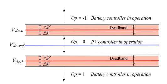
The main objective of the proposed control strategy is to treat the battery as the secondary source in the islanded dcMG,whichisusedonlywhenthemaximumPVpoweris insufficienttofulfilltheloaddemand.Thebatteryalsohelps to regulate the dc-link voltage vdc if it deviates beyond a predefined voltage limits during transients. These limits definea
Fig.2.Proposedoperationcontrollimits.
VoltagebandinwhichonlythePVcontrollerregulatesthe dclinkvoltagewhereas,if vdc isnotwithinthisvoltageband, the BESS converter will operate to help regulating the dc voltage.Here, Vdc-u and Vdc-l aretheupperandlowerlimits ofthedc-linkvoltage,respectively,whichdefinethevoltage band as shown in Fig. 2. There is also a deadband around eachofthesecontrollimitsdenotedby V.Thesedeadbands are set to prevent the battery from turning on and off recursivelyaroundtheboundarylimits.ThePVmaximum power ppv-max is estimated usingtheapproachin[9]. Op represents the battery operation mode (Op = -1 shows chargemode, Op =0showsstandbymodeand Op=1shows dischargemode)and pload istheloadpower.Subsequently, thebatterySoClevelisetimatedusing(1).
SoC(k) = SoC(k -1) - (kkT -s1)Ts(ibat/Cbat) dt, (1)

where k isthesamplenumber, Ts isthetime-step, ibat isthe battery current, and Cbat is the battery capacity. If the batterycurrentisnegative(currentisflowingtowardsthe battery),theSoCwill increaseandviceversa,theSoCwill decreaseif ibat ispositive(batteryisdischarging).Therate ofSoCchangeisdirectlyproportionalto ibat

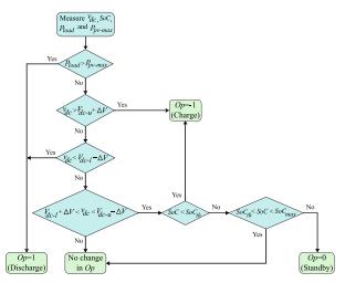
As shown in Fig. 3, if pload is larger than the maximum availablepower ppv-max, (pload > ppv-max),theBESSwill operateanddischargethestoredenergy(Op =1,discharge mode) as the load demand is higher than the maximum power supply from the PV. Otherwise, Op will be updated accordinglybasedonthedc-linkvoltage vdc fluctuation.For instance,if vdc isgreaterthan Vdc-u +V,thebatteryregulates thedclinkvoltagebyabsorbingthepowerfromthedcbus (Op=-1,chargemode).Similarly,if vdc issmallerthan Vdc-lV,showninFig.3,thebatterydischargesas vdc deviationis outoftheallowedbandandthereby, vdc isregulatedbythe BESStotheinnermostboundaries, Vdc-u - V and Vdc-l + V
This function is added to the controller to ensure the stabilityofthedcMGundersuddenlargestepchangesofthe load, during which the PV converter may not provide the requiredfasttransientresponse.Oncethebatteryisableto regulate the dc-link voltage vdc into the innermost boundaries,thebatterySoCiscomparedwithitsreference value SoCth.IftheSoCislowerthan SoCth, Op isupdatedto1andthebatteryisputintooperation(chargemode)tobe charged by the PV excess power generation (ppv-maxpload).OncethebatterySoCreachesto
operationswhentheloadtransientsoccurfrequently.If vdc iswithinthedeadbandzones, Op valuewillnotbeupdated. Whendetermining SoCth value,therearenumerousfactors thatneedto be considered (i.e., typesof batteryandtheir chemical characteristics, charge/discharge rate, working temperature,SoClevel and theloadprofile). Higher SoCth value will increase the number of micro-cycles while the lower value risks having lower stored energy. With the proposedcontrolmethodology,theBESSutilizationandthe numberof partial charge/dischargecyclesissubstantially reduced. As a result, the battery lifetime is prolonged. AccordingtotheabovediscussionsandtheflowchartinFig. 3,thefollowingconditionsneedtobesatisfiedinorderto keepthebatteryinthestandbymode:(i)thebatterySoCis higherthan SoCth (whichtranslatesthatthebatterydoesnot needtocharge),(ii)PVsystemhassufficientpowerforthe loaddemand(ppv-max > pload),and(iii) vdc fluctuationis withinthepre-definedvoltagelimits(PVisabletoregulate vdc toitsreferencevalue vdc-ref ).ThePVpowerreference ppv-ref isgivenby: ppv-ref = ppload pv-max + dp , , Op Op == 00(2)ThePVcontrollercollectsthe Op, ppv-max and pload informationtodetermine ppv-ref .If Op isnot0,thebattery isinoperationandthus, ppv-ref issetto ppv-max.Hence,the PVoperatesatitsmaximumpowerpointinordertoeither reducetheloadshareoftheBESSasmuchaspossible(when pload > ppv-max),ortorestorethebatterySoCto SoCmax (when the battery needs to restore energy). If Op is 0, it translatesthatthebatteryisnotinoperation.Thus,thePV willcompletelytakecontrolof vdc regulationbyadjusting
4. SIMULATION RESULTS
Theperformanceoftheproposedcontrolstrategyisverified experimentallyunderintermittentirradiancechangesand differentloadingconditionswithahardwaresetupshownin Fig. 4. The parameters of the experimental setup are providedinTable.I.Theresultsinthissectionarebasedon theassumptionofhavingaconstantPVcelltemperatureof 25 ◦C.AsshowninFig.5,therearetwopossibleoperating points for the PV power reference ppv-ref: Point A on the left-sideofthe
SoCmax,thebatterycontrollerisswitchedoff(Op=0,standby mode)andonlythePVconvertercontrollerisresponsible for converging vdc to its reference value Vdc-ref. Such thresholdrange(wherethebatterydoesnotneedtocharge), asshowninFig.3,isimplementedtoreducethemicro-cycle
Fig. 6. Case I: Experimental verification of the transient response of theproposed control strategyunder different loadingconditions.(a)PVvoltage,(b)dc-linkvoltage,(c)PV power,PVmaximumpower,loadpowerandbatterypower, (d)PVandbatterycurrents,and(e)SoC.maximumpower point(MPP)andpointBontheright-sideoftheMPP[7],[8]. Operating at the right-side of the MPP provides a faster dynamicresponsethanoperatingattheleftsideasasmall PV voltage change results in a large power deviation. However,thedisadvantageisthatthePVoutputpowerwill haveahigheroscillationevenatthesteady-statecondition.If the PV operates at the left-side of the MPP, the PV output powerbenefitsfromlowerpoweroscillationatthecostof slowerdynamicperformanceascomparedtotherightsideof MPPoperation.Intheexperimentation,thecontrollerlimits thePVoperationtotheleft-sideoftheMPPtoattainthelow poweroscillationwhilethedynamicisenhancedbyutilizing variablevoltage-step.
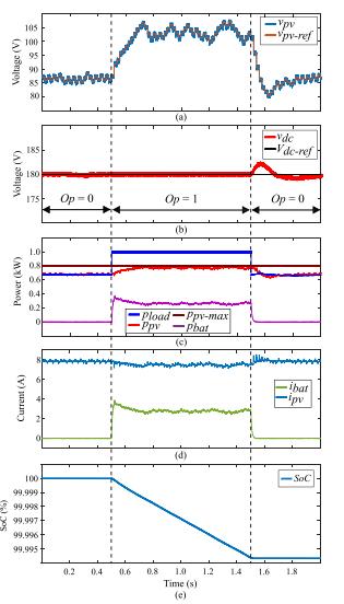
Case I:Inthiscasestudy,theperformanceoftheproposed control strategy under different loading conditions is examinedandresultsareshowninFig.6.TheSoCthreshold limit SoCth
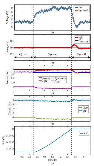
Fig. 7. Case II: Experimental results of the battery SoC preservationinadesiredoperationrange.(a)PVvoltage,(b) dc-link voltage, (c) PV power, PV maximum power, load powerandbatterypower,(d)PVandbatterycurrents,and (e)SoC.isemulatedtobesmallerthanthebatterySoCinthis case (SoC>SoCth). Initially, the PV is supplying power accordingtotheloaddemandof650Wandthebatteryis also not operating as the load demand is below ppv-max (800W) andtheSoCislargerthan SoCth.At t =05s, pload suddenlyincreasesfrom650Wto1000Wasillustratedin Fig.6(b).Since pload islargerthan ppv-max,theoperation status Op isupdatedto1,showninFig.6(b).Hence,thePV increasesitsoutputpowertothemaximumavailablepower andthebatteryconverterisalsoinoperationtosupplythe remainingloaddemandfromthebattery.Attheinstantof loadchange (t =05s),thebatterycurrentsupplyincreases as shown in Fig. 6(d). At the same time, the PV supply increasestoitsmaximumpoweratthesteady-state.Then, the load power pload reduces back to 650 W at t = 15 s. Duringthiscondition,sincethePVhassufficientcapacityto supplythedemandandthebatterySoCisstilllargerthanits reference value (SoC >SoCth), the operation status Op is updatedto0.Hence,thebatteryconverterisdisconnected fromthesysteminordertoreduceitsutilization.Fromthen, only the PV system regulates the dclink voltage vdc to its reference value vdc-ref , as shown in Fig. 6(b). This case studydemonstratesthecapabilityoftheproposedcontrol strategyinsupplyingtheloaddemandwithreducedbattery utilization.

CaseII:Thiscasestudyshowstheuseoftheproposedhybrid control strategytomaintain the SoC within its predefined limits, as shown in Fig. 7. The initial SoC threshold limit SoCth is emulated to be below the SoC of the battery (SoC>SoCth)andtheloaddemandisfixedat650W.Initially, thePVisgeneratingtheloaddemandandthebatterysystem isnotinaction.Anincreasein SoCth,whichishigherthanthe batterySoC(SoC < SoCth),isemulatedat t =05s.
Subsequently,theoperationmode Op isupdatedto-1based ontheproposedstrategyinFig.3,asdepictedinFig.7(b). Thus, the output of the PV is increased to the maximum possible value and any surplus generation from the PV systemissuppliedtothebatteryinordertoincreasetheSoC, asdemonstratedinFigs.7(c)and(d).At t =1.5s,thebattery SoCreachesitsmaximumlimit SoCmax (95%inthiscase). Asaresult, Op isupdatedto0and ppv-ref issettotheload demandplusthepowerdeviationfromthedc-linkvoltage regulation,describedin(2).TheBESSisalsodisconnected fromthesystemanditscurrentbecomeszero,asshownin Fig.7(d).Inthiscase,itcanbeobservedthattheproposed hybridcontrolstrategysuccessfullyexecutesthefunctionof keepingtheSoCwithinthedesiredoperatingrange.
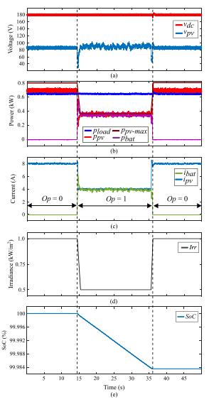
CaseIII:Theperformanceoftheproposedcontrolstrategyis investigated under the fast linear irradiance variations as depictedinFig.8.Theloaddemandisconstantat650Wand the irradiance is initially at 1 kW/m2 The battery SoC is largerthantheemulated SoCth (SoC > SoCth).Thus,thePV power is equivalent to the load demand and the BESS doesnotoperate.At t =145s, theirradiancelinearlydrops to05kW/m2andthePVsupplyisconsequentlyreducedas showninFig.8(b).Sincetheloaddemandislargerthanthe maximumsupplyfromthePV, Op isupdatedto1tofulfillthe loaddemandasshowninFig.8(c).Subsequently,thebattery converterseizestooperate whentheirradianceincreases backto1kW/m2at t =355sbecausethePVhassufficient generationtocaterfortheloaddemandandthebatterySoC is still larger than its threshold limit SoCth. This demonstratesthedynamicperformanceandrobustnessof theproposedcontrolstrategytorapidirradiancechanges.
5. ANALYSIS OF BATTERY LIFE IMPROVEMENT
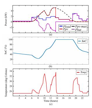
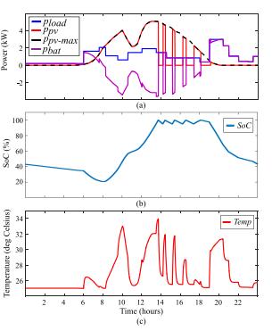
Inordertoevaluatetheeffectivenessoftheproposedcontrol strategy,loadandirradianceprofilesforoneday,asshown in Fig. 9, are utilized in this case study. Firstly, battery lifetimeestimationmodelsareprovidedandafterwards,the estimatedbatterylifetimebyusingtheconventionalcontrol strategy[11],[16],[21]andproposedcontrolstrategyare compared.Theworkingtemperatureofthebatteryisoneof the factors that leads to rapid degradation of the battery lifetime[14],
Fig.8. Case III:Experimentalinvestigationoftheproposed controlstrategyunderintermittentirradiancechanges.(a) PVvoltage,anddc-linkvoltage,(b)PVpower,PVmaximum power, load power and battery power, (c) PV and battery currents,(d)irradianceand(e)SoC.[15].
As the current flows in and out of the battery, power dissipatesasheatintheinternalresistanceofthe battery. The internal battery temperature Tin is estimated by the heat transfer thermal resistance in this case study. The parametersoftheselectedLithium-ion(Li-ion)battery(3.3 V, 70 Ah) are provided in [22]. The battery capacity is designedinsuchawaythatthebatteryiseffectivelyutilized (SoC variation between 100 % max. and 20 % min.). Accordingly, there are four parallel strings of 16 battery banks connected in series. Each battery bank has 70 m internalseriesresistance[23].
Thisresistancevalueisusedtocalculatetheinternalpower lossesofthebattery.Anelectricalequivalentcircuitthermal model is implemented to analyze the battery cell temperature as shown in Fig. 10. Tamb is the ambient temperatureanditisassumedtobe25 ◦C.Inthefollowing, thelifetimestudyisrepeatedforanothercommonbattery type, i.e., lead-acid (LA) battery. The battery lifetime is estimatedbasedonthesameloaddemand,PVgeneration, and battery utilization manners of the proposed and the conventionalcontrols,aspresentedinFigs.11and12.The ratingofeachLAcellis2V, 4Ahandtherearetenparallel stringsof30batterybanksconnectedinseries.Theoverall heat transfer coefficient is 57 WK-1m-2 for the thermal resistance from the cell to the surroundings. The thermodynamic properties of this battery are provided in [26]. Subsequently, the temperature/current dependence

characteristic(9),whichisexperimentallyanalyzedin[26], isusedtoestimatetheLA
Fig.11.Simulationresultsoftheproposedcontrolstrategy underaonedaycasestudy.(a)Loadpower,PVpower,PV maximum power and battery power, (b) SoC, and (c) temperature. Battery cell temperature. T = 362I + 25 (9) among the different LA battery degradation parameters, temperatureisknowntobethemostimpactfulparameter. Hence,theremaininglifetimeoftheLAbattery LLA iswhere Ln isthenominallifeoftheLAbattery, (ti - ti-1) isthetime difference, Ti is the average temperature during the time period ti, Tx isthetemperatureattimeperiod tx,and α=10is thechangeintemperaturecoefficient.Accordingly,theLA battery can last for 1112 days with the proposed control strategyand778dayswiththeconventionalcontrolstrategy beforereachingtheEoL.Itisalsonotedthatthelifetimeof theLAbatteryisrelativelyshorterthantheLi-ionbattery [28].Thus,thiscasestudyexhibitsthattheproposedcontrol strategyprolongstheLi-ionbatteryaging,basedondifferent batterydegradingparameters,by2993%ascomparedto the conventional control strategy (from 1964 days in the conventionalcontrolto2552daysintheproposedcontrol). Similarly, the gained lifetime of the LA battery with the proposedcontrolstrategyisaround42.93%(from778days in the conventional control to 1112 days in the proposed control).Hence,theproposedcontrolstrategydemonstrates thesignificanceof
Fig. 12. Simulation results of the conventional control strategy under an oneday casestudy.(a)Loadpower, PV power,PVmaximumpowerandbatterypower,(b)SoC,and (c)temperature.HavingFPPTcapabilityforthePVsystems instand-alonedcMGs.
CONCLUSION
In this paper, it is obvious that the adaptive and optimal controlstrategyplaysanimportantroleinthedevelopment of solar PV systems. This strategy is based on the combinationbetweentheSTandMPPTinordertoensure that the solar PV panel is capable of harnessing the maximumsolarenergyfollowingthesun’strajectoryfrom dawnuntilduskandisalwaysoperatedattheMPPswiththe improved InC algorithm. The proposed InC algorithm improves the conventional InC algorithm with an approximationwhichreducesthecomputationalburdenas wellastheapplicationoftheCValgorithmtolimitthesearch space and increase the convergence speed of the InC algorithm. This improvement overcomes the existing drawbacksoftheInCalgorithm.Thepaperalsoproposesan improved incremental conductance (InC) algorithm for enhancingthespeedoftheMPPtrackingofasolarPVpanel under various atmospheric conditions as well as guaranteeingthattheoperatingpointalwaysmovestowards theMPPusingthisproposedalgorithm.Theeffectivenessof theproposedcontrolstrategyonprolongingthelifetimeofa lithium-ionbatteryandalead-acidbatteryisinvestigatedvia a simulation case study with one-day load and irradiance curveprofiles

REFERENCES
[1] R. Faranda and S. Leva, “Energy comparison of MPPT techniquesforPVsystems,” WSES Trans. Power Syst.,vol.3, no.6,pp.446–455,2008.
[2]X.Jun-Ming,J.Ling-Yun,Z.Hai-Ming,andZ.Rui,“Design oftrackcontrolsysteminPV,”in Proc. IEEE Int. Conf. Softw. Eng. Service Sci.,2010,pp.547–550.
[3]Z.Bao-Jian,G.Guo-Hong,andZ.Yan-Li,“Designmentof automatictrackingsystemofsolarenergysystem,”in Proc. 2nd Int. Conf. Ind. Mechatronics Autom.,2010,pp.689–691.
[4]W.Luo,“Asolarpanelsautomatictrackingsystembased onOMRONPLC,”in Proc. 7th Asian Control Conf.,2009,pp. 1611
1614.
[5]W.Chun-Sheng,W.Yi-Bo,L.Si-Yang,P.Yan-Chang,andX. Hong-Hua,“Studyonautomaticsun-trackingtechnologyin PV generation,” in Proc. 3rd Int. Conf. Elect. Utility DeregulationRestruct.Power Technol.,2008,pp.2586–2591.
[6]C.AlexandruandC.Pozna,“Differenttrackingstrategies for optimizing the energetic efficiency of a photovoltaic system,” in Proc. Int. Conf. Autom., Quality Testing, Robot., 2008,pp.434
439.
[7]R.Sridhar,S.Jeevananthan,N.T.Selvan,andP.V.Sujith Chowdary, “Performance improvement of a photovoltaic arrayusingMPPTP&Otechnique,”in Proc. Int. Conf. Control Comput. Technol.,2010,pp.191–195.
[8]N.M.RazaliandN.A.Rahim,“DSP-basedmaximumpeak power tracker usingP&Oalgorithm,”in Proc. IEEE 1st Conf. Clean Energy Technol., 2011, pp. 34–39.
[9]L.Chun-XiaandL.Li-qun,“Animprovedperturbationand observationMPPTmethodofphotovoltaicgeneratesystem,” in Proc. 4th IEEE Conf. Ind. Electron. Appl.,2009,pp.2966–2970.
[10]Y.Jung,J.So,G.Yu,andJ.Choi,“Improvedperturbation and observation method (IP&O) of MPPT control for photovoltaicpowersystems,”in Proc.31stIEEEPhotov.Spec. Conf.,2005,pp.1788–1791.
[11] G. C. Konstantopoulos and A. T. Alexandridis, “Nonlinear voltage regulator design for DC/DC boost converters used in photovoltaic applications: Analysis and experimental results,” IET Renew. Power Gen., vol.7,pp.296–308,May2013.

[12] A. Tofighi and M. Kalantar, “Power management of PV/battery hybrid power source via passivity-based control,” Renew. Energy, vol.36,pp.2440–2450,Sep.2011.
[13] H. Cai, J. Xiang, W. Wei, and M. Z. Q. Chen, “V-dp/dv droopcontrolforPVsourcesinDCmicrogrids,” IEEE Trans. Power Electron.,vol.33,no.9,pp.7708–7720,Sep.2018.
[14]P.Ruetschi,“Agingmechanismsandservicelifeoflead–acid batteries,” Power Sources, vol. 127, pp. 33–44, Mar. 2004.
[15]B.ShabaniandM.Biju,“Theoreticalmodellingmethods forthermal managementof batteries,” Energies,vol.8,pp. 10153–10177,Sep.2015.
[16]H.Mahmood,D.Michaelson,andJ.Jiang,“Decentralized powermanagementofaPV/batteryhybridunitinadroopcontrolledislandedmicrogrid,” IEEETrans.PowerElectron., vol.30,no.12,pp.7215–7229,Dec.2015.
[17] Y. Shan, J. Hu, K. W. Chan, Q. Fu, and J. M. Guerrero, “Model predictive control of bidirectional DC–DC converters and AC/DCinterlinkingconverters Anewcontrolmethodfor PV-wind-battery microgrids,” IEEE Trans. Sustain. Energy, vol.10,no.4,pp.1823–1833,Oct.2019.
[18]T.Dragicevic,J.M.Guerrero,J.C.Vasquez,andD.Škrlec, “Supervisory control of an adaptive-droop regulated DC microgridwithbatterymanagementcapability,” IEEETrans. Power Electron.,vol.29,no.2,pp.695–706,Feb.2014.
[19]G.Angenendt,S.Zurmühlen,H.Axelsen,andD.U.Sauer, “ComparisonofdifferentoperationstrategiesforPVbattery home storage systems including forecast-based operation strategies,” Appl. Energy,vol.229,pp.884–899,Nov.2018.
[20]A.Narang et al.,“Analgorithmfor fastflexiblepower pointtrackinginphotovoltaicpowerplants,”in Proc. 45th Annu. Conf. IEEE Ind. Electron. Soc. (IECON), vol.1. Lisbon, Portugal,Oct.2019,pp.4387–4392.
[21] Y. Yang, Y. Qin, S.-C. Tan, and S. Y. R. Hui, “Efficient improvementofphotovoltaic-batterysystemsinstandalone DC microgrids using a local hierarchical control for the batterysystem,” IEEE Trans. Power Electron.,vol.34,no.11, pp.10796–10807,Nov.2019.
[22] Y. Xiao, “Model-based virtual thermal sensors for lithium-ion battery in EV applications,” IEEE Trans. Ind. Electron.,vol.62,no.5,pp.3112–3122,May2015.
[23] Li-Ion Battery Datasheet, EEMB, Hongkong, 2021. [Online]. Available: https://www.ineltro.ch/media/downloads/SAAItem/45/45 958/36e3e7f32049-4adb-a2a7-79c654d92915.pdf
[24] B. Xu, A. Oudalov, A. Ulbig, G. Andersson, and D. S. Kirschen,“Modelingoflithium-ionbatterydegradationfor celllifeassessment,” IEEE Trans. Smart Grid,vol.9,no.2,pp. 1131–1140,Mar.2018.
[25] M. Musallam and C. M. Johnson, “An efficient implementationoftherainflowcountingalgorithmforlife consumptionestimation,” IEEE Trans. Rel.,vol.61,no.4,pp. 978–986,Dec.2012.
Author details:
Mr. Mandli Vamshidhar Reddy received a B.Tech in electricalandelectronicsengineeringfromBharatInstitute of Engineering and Technology (BIET), Ibrahimpatnam, RangaReddyDist.AndstudyingM.techinelectricalpower systemsatHolyMaryInstituteofTechnologyandScience, Bogaram, Medchal Dist, Hyderabad, India in the dept. electricalandelectronicsengineering.

Dr.Sivaganesan Sivanantham receivedtheB.E.inElectrical andElectronicsEngineeringfromUniversityofMadras,TN in2003and M.Tech.in Power Electronics & Drives from SASTRA University, TN in 2006and the Ph.D. degree in ElectricalEngineeringfromVelsUniversity,Tamilnaduin 2017. He is currently an HoD & Professor of Dept. of Electrical&ElectronicsEngineeringatHolyMaryInstituteof TechnologyandScience,Hyderabad.Hisresearchinterests include photovoltaic systems, renewable energy systems, power electronics, and control of power electronics interfaces.


