CAD modeling of fluid domain with twisted tape inserts using Creo Design software
Shailesh Pandey1, Purushottam Sahu2, Ghanshyam Dhanera31 Research Scholar, BM College of Technology, Indore

2Professor and HEAD, BM College of Technology, Indore
3 Assistant Professor, BM College of Technology, Indore, MP ***
Abstract - This study aimed to analyze the effect of outer and inner tube flow rates on heat transfer coefficients in a tube-in-tube helical coil heat exchanger using computational fluid dynamics (CFD) analysis. The CFD simulation employed a fluid mixture of Al2O3/water with a 1% volume fraction, and different fluid inlet velocities ranging from 0.01m/s to 0.05m/s were examined. Several parameters, including temperature distribution, pressure drop, heat transfer coefficient, and Nusselt number, were compared. The Nusselt number comparison curve indicated that CuO/water nanofluids with a 1% volume fraction exhibited the lowest Nusselt number, while a slightly higher Nusselt number was observed for CuO/water nanofluids with a 2% volume fraction. Notably, the highest heat transfer characteristics were observed for Al2O3/water with a 1% volume fraction due to the enhanced thermal conductioninthe1%Al2O3vaporcomponentofthefluid.
Key Words: Heat Transfer, Pressure Drop, Reynolds Number,Nusseltnumber,CFDModel
1. INTRODUCTION
Heat exchangers demonstrate satisfactory thermal efficiency for efficient commercial operation of industrial machinery. To enhance the thermal efficiency of heat exchangerpipesthroughconvectionheattransfer,various strategiescanbeemployed,bothactiveandpassive.These strategies encompass modifications to the fluid passage, incorporation of spin generators, and utilization of Nano fluids. The primary objectives of these methods are to reduce plant irreversibility, improve heat transfer efficiency, optimize volume, and enhance fluid flow characteristics.
Researchers worldwide have been investigating ways to enhance convective heat transfer efficiency in tubes by exploring different types of additives as liquid phase transformers. These additives contribute to changes in addition geometry, normal velocity gradients, and act as inducers of mixing, disorder swirl generators, and dwell time enhancers. The transfer of thermal energy occurs when the liquid passes from one fluid to another within the heat exchanger. Heat transmission can occur through the fluid surface or between solid-fluid particles. Thermal
gradients or temperature variations are crucial for heat transmission among liquids or from the liquid to the surroundings.
Heat exchangers find widespread use in the heating and cooling of fluids, as well as in processes such as evaporation andcondensation. They are alsoemployed in applications such as sterilization and pasteurization. In heatexchangers,fluidsaresegregatedbywallstoprevent intermixing, and such heat exchangers are referred to as retrievers.
The application of nanofluids in heat exchangers is a promising approach to address the issue of low thermal conduction and reduced efficiency in complex fluid systems. When the thermal properties of the fluid are enhanced, it becomes possible to improve heat transmissionwithinheatexchangers,whichinturnallows for more compact designs. One effective method is to increase the heat-carrying capacity by introducing finely dispersedparticlesintothefluid.
Different typesofpowders, suchasmetallic,non-metallic, and polymeric particles, can be incorporated to form slurries in liquid mediums. These fully suspended fluids exhibit higher heat capacities compared to plain fluids, resulting in improved heat transfer efficiency within the heat exchanger. A mechanical application test was conducted to observe the impact of slurry mass, droplet size,scale,andflowrateonheatexchangebehavior.
While suspended particles typically have dimensions ranging from micrometers to millimeters, their large size can lead to issues such as scratching and blockage. To overcome these challenges, fluids with nanoparticles are utilized to achieve limited practical issues in heat exchange enhancement. Nanoparticles offer a promising approach for improving fluid heat exchange characteristics. Particles smaller than 100 nm exhibit unique properties distinct from those of ordinary solids. Nano-sized powders demonstrate enhanced interactions compared to micron-sized particles. Researchers have explored the suspension of nanoparticles in fluids to createhighlyeffectiveheatexchangefluids.
By incorporating nanophase elements into heating and coolingfluids,theheatexchangeperformanceoftheliquid canbesignificantlyenhanced.
Flowovercylindrical systemsfindsextensiveapplications in various fields, including heat exchangers, cooling systems, and thermal equipment. In the context of a heat exchanger,twocrucialphenomenaoccur:fluidflowwithin thechannelsandtheheattransfer betweenthefluidsand the channel walls. Enhancements to heat exchangers can beachievedbyimprovingtheseprocesses.
Firstly, the rate of thermal exchange depends on the surface area-to-volume ratio, implying that smaller channelsresultinhighercoefficientsofthermalexchange. Additionally, optimizing the properties of thermal exchange fluids, such as nanofluids, within a heat exchanger can significantly increase the thermal transfer coefficient.
2. PROBLEM IDENTIFICATION:
Investigating the impact of nanofluids on enhancing heat transfercharacteristicsinhelicalinserttubingrequiresan examinationoftheiruseinaheatexchanger,asnanofluids have the potential to significantly improve heat transfer ratescomparedtoconventionalbasefluids.
3.2 RESEARCH GAP reframed: Existing research has focused on enhancing heat transfer using twisted tapes and nanofluids, as well as optimizing parameters for improved heat transfer. However, there is a need to explore the application of Al2O3/water and CuO/water nanofluids to enhance heat transmission and reduce frictioncoefficients.
2.2 OBJECTIVES:
Theobjectivesofthisstudyareasfollows:
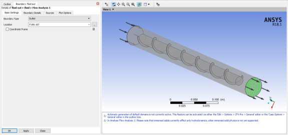
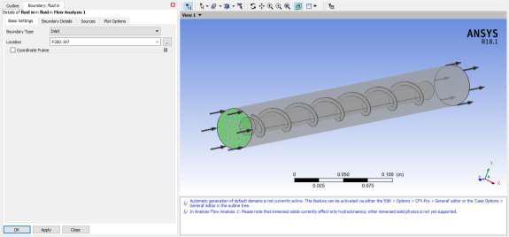
1. Create a fluid domain model with twisted tape insertsusingCreodesignsoftware.
2. Perform CFD analysis using water as the base fluid to determine temperature, velocity, pressure, and heat transfer coefficient. Conduct theanalysisatdifferentReynoldsnumbers.
3. Repeat the CFD analysis after replacing the base fluidwithAl2O3/waternanofluids.
4. Repeat the CFD analysis after replacing the base fluidwithCuO/waternanofluids.
5. Basedontemperatureanalysisandotherrelevant factors, evaluate the effectiveness of the different fluidsandidentifythemostsuitablenanofluidfor heat transfer enhancement in helical insert tubing.

3. METHODOLOGY
The fluid inlet conditions are defined by a velocity of 0.01m/s and a temperature of 300K. In different cases studied, the inlet velocity is varied to 0.02m/s, 0.03m/s, 0.04m/s, and 0.05m/s. additionally, a heat flux of 100,000W/m2 is applied to the outer wall of the cylindricaldomain.
The first computational fluid dynamics (CFD) simulation involves utilizing water as the base fluid. The analysis is carried out at various fluid inlet velocities, namely 0.01m/s, 0.02m/s, 0.03m/s, 0.04m/s, and 0.05m/s. The properties of the water employed in the examination are specifiedintable5.1.

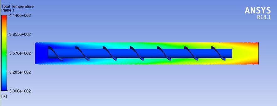
The given diagram, labeled as Figure 3.2, displays the temperature distribution of water functioning as a fluid with a kinematic viscosity of 0.01. This temperature distributionwasobtainedthroughtheimplementationofa helicalscrewtapeinsertinapipe.Thecontourplotvividly portrays an escalation in temperature from the inlet wall to the outlet wall of the fluid. Towards the inlet, the temperature is almost 300K, indicated by a shade of dark blue. Moving towards the outlet, there is a significant rise in temperature with a mid-region temperature change from 300K to 357K, depicted by a green shade, and 414K near the outlet edge, shown by a red color, with a yellow shadeatthecentralarea.
Figure 3.4 showcases a temperature plot of Al2O3/water, where the fluid has an inlet velocity of u = 0.01. The plot specifically depicts the temperature distribution within a pipeequippedwithahelicalscrewtapeinsert.
Thecontourplotvisuallyrepresentsthegradualelevation of temperature as one progresses from the fluid inlet towardsthefluidoutletwall.Initially,atthefluidinlet,the temperatureisdepictedbyadeepblueshade,symbolizing a value of approximately 300K. However, as one moves closertotheexit,thetemperaturesteadilyrises.
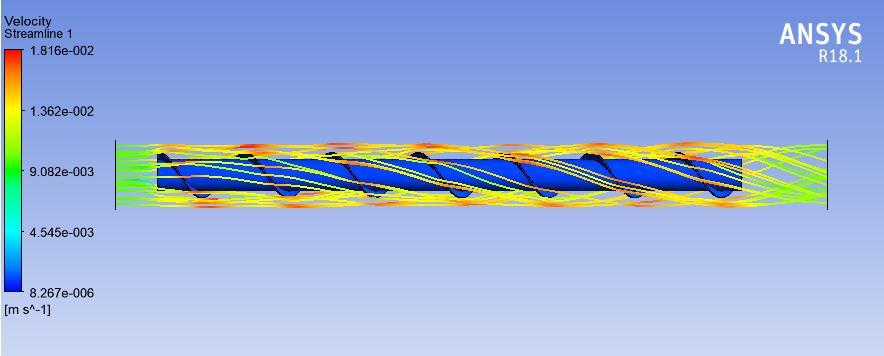
Accordingtotheinformationprovided,Figure3.3 (upper) portrays a velocity streamline plot of CuO/water functioning as the fluid. The plot elucidates the flow characteristics of the fluid throughout the system. The fluidexhibitsaninletvelocityof0.009m/supon entering the domain. As the fluid traverses through the helix, the streamline plot reflects variations in the flow behavior, converting from a streamlined flow to a turbulent flow in this section. At the helix region, the fluid velocity is illustratedas0.018m/s,depictedbythevibrantredlines, indicating an escalation in velocity compared to the inlet velocity. The turbulent flow depicts increased mixing as well as fluctuations in velocity and pressure experienced by the fluid. The streamline plot demonstrates an equivalent fluid velocity of 0.009 m/s at the outlet, which issimilartotheinletvelocity.Thussignifyingthatthereis nonotablechangeinvelocitybetweentheinletandoutlet regionsofthedomain.
The fifth Computational Fluid Dynamics (CFD) analysis is carriedoututilizingAl2O3/water(2%volumefraction)as fluid. The analysis is conducted for different fluid inlet velocities, comprising of 0.01m/s, 0.02m/s, 0.03m/s, 0.04m/s,and0.05m/s.
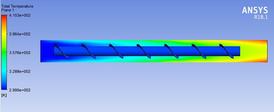

Within the mid-region, the contour plot demonstrates a transition from 300K to 357K, observable through the presence of a green hue. Moreover, near the exit, the temperature intensifies further, reaching a value of 415K. This intensified temperature is illustrated by a red color along the edge and a yellow shade at the center of the contourplot.
Figure 3..5 and Figure 3.6 showcase the RN vs NN curve for both 1% and 2% volume fractions of Al2O3/water. As observed, an increase in RN corresponds to a concurrent increaseinNN.Remarkably,theminimumobservedvalue of NN is 1591, while the maximum RN value recorded is 7928.
4. CONCLUSION:
The present study utilized numerical simulation to investigate the impact of nanofluids on heat transfer characteristics within a spiral screw tape inserted tube. Using computer simulation software allowed for an efficient and cost-effective means of evaluating fluid flow and heat transfer characteristics as compared to experimental methods. Key findings from the study include:
1. An increase in Reynolds number (RN) corresponded to an increase in Nusselt number (NN) across all fluid types, indicating an enhanced frequency of heat transfer at higherfluidvelocitiesandturbulentflowconditions.
2. The use of Al2O3/water nanofluids significantly improvedheattransfercharacteristicsinwater.
3. In contrast, the use of CuO/water nanofluids led to lower heat transfer efficiency despite water's higher frictionfactor.
4. Specifically, the use of Al2O3/water nanofluids led to a 43.7% increase in heat transfer compared to water at a fluidvelocityof0.01m/s.
5.Moreover, comparedto waterat a fluid velocity of 0.03 m/s, the use of Al2O3/water nanofluids resulted in a 41.5%improvementinheattransfer.
Overall, the results of this study demonstrate the effectiveness of nanofluids in enhancing heat transfer characteristics in pipes, with Al2O3/water nanofluids showingparticularpromise.
References
[1] L.H. Tang, M. Zeng, Q.W. Wang, Experimental and numericalinvestigationontheair-sideperformanceoffinand-tube heat exchangers with various fin patterns,
Experimental Thermal and Fluid Science 33 (2009) 818–827.
[2] Mao-Yu Wen, Ching-Yen Ho, Heat-transfer enhancement in a fin-and-tube heat exchanger with improved fin design, Applied Thermal Engineering 29 (2009)1050–1057.
[3] ParinyaPongsoi, PatcharapitPromoppatum, SantiPikulkajorn, Somchai Wong wises, Effect of fin pitches on the air-side performance of L-footed spiral finand-tube heat exchangers, International Journal of Heat andMassTransfer59(2013)75–82.
[4] A. Nuntaphan, T. Kiatsiriroat, C.C. Wang, Airside performance at low Reynolds number of cross-flow heat exchanger using crimped spiral fins, International Communications in Heat and Mass Transfer 32 (2005) 151–165.
[5] ParinyaPongsoi, SantiPikulkajorn, ChiChuan Wang, SomchaiWongwises, Effect of fin pitches on the air-side performance of crimped spiral fin-and-tube heat exchangers with a multipass parallel and counter crossflow configuration, International Journal of Heat and MassTransfer54(2011)2234–2240.
[6] ParinyaPongsoi, SantiPikulkajorn, ChiChuan Wang, SomchaiWongwises,Effect ofnumberoftube rowson the air-side performance of crimped spiral fin-and-tube heat exchanger with a multi-pass parallel and counter crossflow, International Journal of Heat and Mass Transfer 55 (2012)1403–1411
[7] ThirapatKuvannarat, Chi Chuan Wang, Somchai Wong wises, Effect of fin thickness on the air-side performance of wavy fin and heat exchangers under dehumidifying conditions, International Journal of Heat and Mass Transfer49(2006)2587–2596
[8] Chi-Chuan Wang, Jane-SunnLiaw, BingChwen Yang, Airside performance of herringbone wavy fin-and-tube heat exchanger data with larger diameter tube, InternationalJournalofHeatandMassTransfer54(2011) 1024
1029.
[9] Han-Taw Chen, Wei-Lun Hsu, Estimation of heat transfer coefficient on the fin of annular-finned tube heat exchangers in natural convection for various fin spacings, InternationalJournalofHeatandMassTransfer50(2007) 1750–1761.

[10] JayaramThumbe, Samuel R, Rajath K, SaiSuparna K &RajuPoojari, March 2017 Computational analysis of double pipe counter-flow heat exchanger using fins attached to the inner pipe. International Journal of Engineering Researches and Management Studies
[ICAMS:]98
107
