ANALYSIS OF SKEWED COMPOSITE BRIDGES
Govind Kasat 1 , Dr. Chandrakant Pol2
Abstract - Bridges are the important components of the Highway and Railway Transportation System. Failure of Bridges due to natural and manmade hazards may cause significant disruption to the transportation system and may affect its performance. Thus it results in major economic losses. Thus Safety and Serviceability of bridges have always been a great concern to Civil Engineering Profession. Bridges areaveryspecialtypeofStructure.Theyarecharacterizedby SimplicityinGeometryandLoadingCondition.TheReinforced Concrete Bridges are usually subjected to Uniformly Distributed Dead Load, Vehicular Live Loads, and transfers same to the support through flexure, Shear, and Torsion. NewlyDesignedBridgeStructuresareoftenSkewedStructures and they are often used in highly congested Urban Areas where there is Space Constraint or in mountainous terrain areas. If a Road alignment crosses the river or any other obstructions at an angle other than 90 degrees then Skewed BridgeStructure isnecessaryastheyareEconomicalandmost prominent Structures in such conditions. However, force flow in Skewed Structure is much more complicated than Conventional Bridge Structure. Various Promising methodologieslikeGrillageanalysis,FiniteElementMethod,or Load Distribution Method are available. But Finite Element Method is considered the most suitable and precise methodology of analysis. This technique requires high precisioninDataCollection,Modelling,andanalysisofSkewed Structure and interpretation of results. In this research, an attempt has been made to study variations of various parameters like BendingMoment,ShearForce,andTorsional Moment with different skew angles ranging between 0 Degreesto70Degreesatanincrementof10Degreeseach.For our study, we have taken into consideration four major Loading Conditions i.e. 3Class A Loading Condition, Class A+70R Far, Class A + Class 70 R Near, and Fatigue Loading Condition as per IRC Guidelines. For in-depth analysis of the Skewed Bridge structure, 7 models for each loadingcondition i.e. overall 28 models were developed in MIDAS CIVIL for our analysis purpose.
1. INTRODUCTION
This article gives us a brief idea about Skewed Bridges. Generally, due to complex intersections at various places such as Highways, Railway Crossings, and River Crossing, there is a continuously growing demand for such Skewed Bridges to distribute entire traffic without Congestion. Skewed Bridges for the angle between 0 degrees and 30
degrees are considered Straight Bridges as variation in parameterlikeShearForce,BendingMomentandTorsional Moment is very small beyond 30 degrees there is a huge variationinparameters.ThemainMotiveofourresearchis todeterminethemostCriticalanglei.e.Theanglesatwhich there is a sharp increment or decrement in Shear Force, BendingMoment,and Torsional Moment. Generally,these are the points or skew angles at which Design must be carriedoutmorepreciselyandrigorouslytoavoidanytype of failure. For our analysis, we have made use of MIDAS CIVILSoftware.
1.1 Software and its features
MIDAS Civil is a Finite Element Analysis Software developedbyMIDASoftusedforbridgeanalysisanddesign. MIDAS Civil Combines powerful pre and post-processing featureswithanextremelyfastsolver,whichmakesbridge modelingandanalysissimples,quickandeffective.Also,there areseveraleasyparametermodificationtoolsavailablethat canbeusedforparametricanalysisleadingtooptimizedand economicaldesign.
1.2 Features
MIDASCivilprovidestheuserwithunlimitedand efficientmodelingmethodsforanytypeofproject.
MIDASCivilprovidestheuserwithvariousanalysis functions for any type of analysis. It is used for linear analysis but is also capable of carrying out geometricnonlinearanalysis.
Gets detailed design reports. Design features provide detailed and clear calculation histories, enablingcheckingthecapacityofselectedsections formomentshearandtorsion.
2. Identify, Research and Collect Ideas
Fromthestudyofvariousliteraturepapers, itwas foundthatverylimitedstudyhasbeencarriedover skewed bridges and even it doesn't hold much relevanceinIndianPerspectiveduetodifferencesin design Live Load Standards, and type of bridges builthere.

Thus it doesn't provide any help to designers regardingquickestimationoftheBendingMoment, Shear Force, and Torsional Moment which are of primeinterest.
WhiledesigningskewedBridgesmosttediousjobis toidentifythemostcriticalskewangle.
Buttoidentifyacriticalanglethemostimportant task is to design Skewed Bridges for different loadingConditionsasperIRCStandards.
Noneoftheresearchershavecarriedoutdetailed studiesregardingidentifyingcriticalanglesasper IndianStandard.
TheAdvantageofidentifyingaCriticalangleisthat while designing we can consider necessary precautionstoavoidfailureofbridgestructures.
TheDetailedMethodologythatwehaveadoptedto identifytheCriticalskewangleisdiscussedinthe methodologymentionedbelow.
3. METHODOLOGY
The most important task was to select the appropriatedimensionsofourskewedstructure.So theLiteraturestudyandstudyingvariousjournals and various books helped in selecting the appropriatedimensionsofourstructure.Oneofthe books that helped me a lot in my entire work is “Design of Bridges by N.Krishnaraju”.
After the selection of appropriate dimensions, we started modeling our skewed structures with different skewed angles in MIDAS Civil. But only modeling the bridges with different skew angles would not give us a clear idea regarding the performanceandeffectofSkewedBridges.Also,it wouldnotgiveus aclearidea regardingthemost criticalangleatwhichsufficientsafetyprecautions arenecessary.
So to overcome all the above situations and get a clearpictureregardingperformance,impacts,and locate the most critical skew angle which is the primaryfocusofourresearchwemodeledSkewed Bridgeswithskewanglesstartingfrom0Degrees to70Degreesincreasingby10Degrees.
Also, we have considered different IRC Loading Conditionsi.e.3ClassA,ClassA+70RNear,Class A+70RFar,andFatigueLoadingConditionforin-

depth analysis and to get a clear idea regarding performance and impacts of skewed Bridge Structure.
So for each loading condition, we designed 7 models.Thusoverall28modelsweredevelopedfor in-depth analysis of a skewed structure which helped us to identify the most critical Skewed angles.
4. MODELLING AND ANALYSIS:
ConsideraSimplySupportedBridgeofspan36metersand Total width of the bridge is 12 meters which is analyzed usingMIDASCivilSoftware.Detailedinformationaboutour modelisprovidedbelow:ThethicknessoftheDeckSlabis 220 mm, the Clear Carriageway width is 11 meters, End Barriers are 0.5 meters on each side.The thickness of the wearingcourseis100mm,WeightDensityofthewearing courseis22KN/M3.
Girder Details:
Consistsof5girderswith2.5-metercenter-to-centerspacing inTransverseDirections.GirdersareprovidedwithDiagonal Bracings. Width of Top Flange: 400mm, Width of Bottom Flange: 850mm, Thickness of Top and Bottom Flange: 25mm.Heightofweb:2045mm,Thicknessofweb:12mm.

FIG 1) DETAILS OF GIRDER

STEPS TO BE FOLLOWED WHILE MODELING IN MIDAS CIVIL:
1. DefineMaterialProperties
2. DefineTimeDependentProperties.
3. DefiningSectionProperties.
4. ModelingofstructureinMIDASCivil
5. SpecifyingloadingconditionsasperIndian Standards.

6. SpecifyingDifferentconditionsofthelane.
7. SpecifyingConstructionStageswhichmajorly includestwostages
a) GirderonlyStage.
b) CompositeStage
8. ConstructionStageAnalysis.
9. Runanalysis.
10. Computationofresults.
5. ANALYSIS AND RESULTS:
Analysis of 28 m long and 12 m wide Bridge for different skew angles ranging from 0 degrees to 70 degrees with increment @10 degrees was done by using MIDAS Civil Software which is based on Finite Element Approach. For ouranalysispurposetotal of28modelsweredesigned by takingintoconsiderationofDeadLoadandLiveLoadasper IRC 6:2017. For our entire analysis we have taken into consideration Four Loading Condition 3 CLASS A, CLASS A+70 R NEAR, CLASS A + 70 R FAR, Fatigue Loading Condition.Themainmotiveofourentireworkistoestimate CriticalSkewangleswhichifpropernecessarymeasuresare not taken may lead to the failure of the structure. Critical Skew angles are the locations at which there is a sudden change in Bending Moment, Shear Force, and Torsional Moment.
5.1. RESULTS:
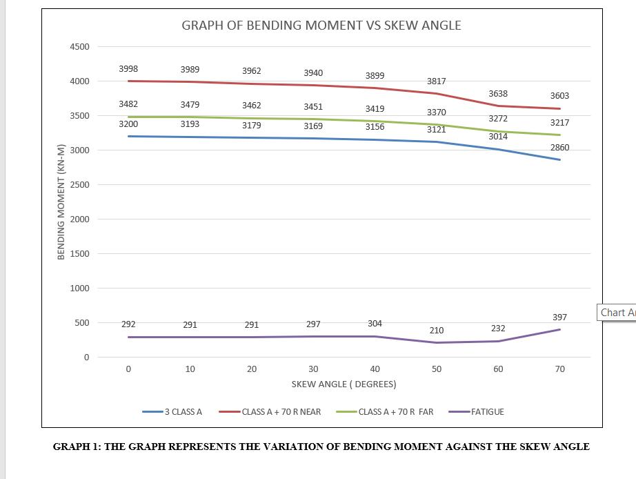
5.1.1. ResultsofBendingMoment(KN-M)for3CLASSA, CLASSA+70RNEAR,CLASSA+70RFAR,Fatigue LoadingConditions.

TABLE 1: DATA REPRESENTING BENDING MOMENT FOR VARIOUS LOADING CONDITIONS IN KN-M
5.1.2. ResultsofShearForce(KN)for3CLASSA,CLASSA+ 70R NEAR,CLASSA +70R FAR &FatigueLoading Condition.
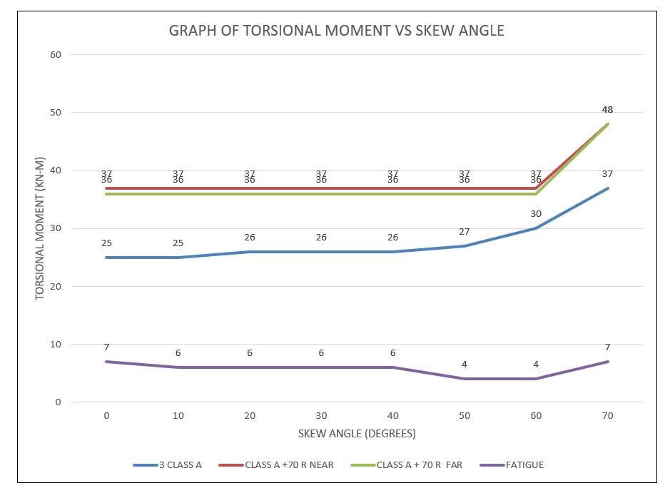
5.1.3. ResultsofTorsionalMoment(KN-M)for3CLASSA, CLASS A + 70R NEAR, CLASS A+ 70R FAR, and FatigueLoadingCondition.
6. CONCLUSIONS:
1. For3ClassAloadingconditionsitwasfoundthat the Bending moment decreases linearly up to 60 degrees but above 60 degrees there is a sharp decreaseintheBendingmoment.
2. For3ClassAloadingconditionsitwasfoundthat Shear force increases up to 30 degrees and then between30to60degreesitdecreasesandabove60 degreesthereisaSharpdecrease.
3. Fromthestudy,itwasfoundthatforClassA+70R NearloadingconditionBendingMomentdecreases Linearly between 0 degrees and 60 degrees skew angleabove60degreesthereisasharpdecrease.

4. FromthestudyitwasfoundthatforClassA+70R Near loading condition Shear Force increases linearly between 0 degrees and 30 degrees skew angle for 40 degrees to 60 degrees shear force decreases linearly above 60 degrees skew angle thereisasharpdecrease.

5. Fromthestudy,itwasfoundthatforClassA+70R Far loading condition Bending Moment decreases Linearly between 0 degrees and 60 degrees skew angleabove60degreesthereisasharpdecrease.
6. FromthestudyitwasfoundthatforClassA+70R FarloadingconditionShearForceincreaseslinearly between0degreesand20degreesskewanglefor 30degreesthereisasharpdecreaseagainfrom40 degreesto60degreesitincreaseslinearlyabove60 degreesthereisasharprise.

7. FromthestudyitwasfoundthatforFatigueloading conditionBendingMomentincreaseslinearlyupto 40 degrees skew angle above 40 degrees skew angle, there is a sharp decrease and it increases linearly up to 60 degrees, and above 60 degrees thereisasharpincrease
8. FromthestudyitwasfoundthatforFatigueloading conditionShearForcedecreaseslinearlybetween0 degreesand40degreesskewangleandabove40 degrees there is a sharp decrease again for 40 degreesto60degreesitincreaseslinearlyabove60 degreesthereisasharprise.
7. RECOMMENDATIONS:
1. FromalltheaboveConclusionswecansuggestthat the most critical angle is 30 Degrees and 60 Degrees. So while designing the Bridges for those specificskewanglesnecessarypreventivemeasures mustbetakenintoconsiderationfromasafetyand economicconsiderationpointofview.
2. From the study, it is recommended that the maximumskewanglemustbelessthan30degrees as far as possible from a safety and economic considerationpointofview.WhileDesigningSkew Bridgesforanglesmorethan30degrees,Designers should be concerned about Torsion and take all necessarystepsforsafeandeconomicaldesign.
REFERENCES:
1. Dawood. M, January 2006, “Design guidelines for strengtheningofsteelconcretecompositebeamswith high modulus CFRP Materials” North Carolina State University,USA.
2. JayaKrishnan.TJ;LakshmiPriyaR,May2017,“Analysis of Seismic Behaviour of a Composite Bridge using ANSYS”,“InternationalJournalofEngineeringResearch & Technology (IJERT), Shree Narayana Institute of Technology,Kerala.
3. K.Narmashiri&M.Z.Jumaat,January2010, "Numerical StudyonStrengtheningCompositeBridges” "Journalof StructuralEngineering",UniversityofMalaya,Malaysia.
4. Wenliang Hu, Yuan Li, Haoyun Yuan; December 2020, "ReviewofExperimentalStudiesonApplicationofFRP for Strengthening of Bridge Structure", "International Journal of Advances in Materials Science and Engineering"ChangaUniversity, China.
5. AlpeshJain,Dr.J.N.Vyas;August2016,“ModalAnalysis ofBridgeStructureUsingFiniteElementAnalysis”MITM Ujjain,India.
6. KavyaKesavan,AswiniJ;June2020,"Analyticalstudyof steel concretecompositeslab with profiled steel deck and different shear connector configurations" "International Journal of Engineering Research & Technology (IJERT)" SCMS School of Engineering and Technology,Kerala,India.
7. MuhammadHasan,April2016,“DynamicResponseof Skewed Multi-Span Steel Composite Bridge”; “International Research Journal of Engineering and Technology”; Anna University Regional Campus, Tamilnadu,India.
8. ManjunathK,H.R.Prabhakar,MahadevMAchar;Sept 2016, “Skew Effect on the Design of Composite Super StructuresinBridges”,“InternationalResearchJournal of Engineering and Technology (IRJET)”; UBDTCE, Davangere.Karnataka,India.
9. MohanLal,Vedpal,RavinderKumar;Sept2016,“Study of Skewness Angle in Reinforced Concrete Girder Bridges”; “International Journal New Technology and Research”;RPIITBastara,Karnal(Haryana)

