Volume: 10 Issue: 07 | July 2023 www.irjet.net


Volume: 10 Issue: 07 | July 2023 www.irjet.net

1PG Student, Structural Engineering Department, Government College of Engineering, Karad, Maharashtra, India Professor, Structural Engineering Department, Government College of Engineering, Karad, Maharashtra, India
***
Abstract - It has been a year since bridge engineers and designers not only considered the stability of bridges but also aesthetics as well as efficiency. So in this paper, an arch bridge is considered for study, which satisfy both conditions. In this study, we changed the rise of an arch of the bridge and deck positions, analyzed the behaviour of the bridge by deflection, bending moment, and self-weight. By comparing all these parameters, we propose an alternative lightweight and more stable bridge structure.
Key Words: Steel Arch bridge, arch rise change, deck positions,deflectioninbridges,lightweightbridge.
Overtheyears,peoplehaveconstantlylookedforways to move their goods from one location to another. It was difficult and time-consuming to cross across valleys, rivers, or other impediments with horses and camels in the past. This was done by going along the rivers and valleys in search of ideal crossing locations, which took a lotofeffort.Afteranumberofyears,increasedpopulation led to increased demand for goods like agricultural products as well as the use of increasingly sophisticated and substantial vehicles like carts. This complicated the transportprocessevenmore.Thisgaverisetotheconcept of building a bridge over rivers and valleys to provide much quicker access in order to meet the demands of the expandingpopulation.Nowthesestructuresareknownas bridges.
A bridge is a structure that spans natural or artificial materials to give access over barriers like valleys, rugged terrain, or water bodies. When the earliest modern civilizations emerged in Mesopotamia in antiquity, they were initially employed. After that, engineering, manufacturing, and understanding of new materials for buildingbridgesmovedbeyondnationalborders,allowing for the gradual but steady development of bridges throughouttheworld.
First modelling of arch bridge structures insap 2000 with differentriseratio(L/3,L/4,L/5,L/6).
Apply the pedestrian load of 3.6kN/m^2, live loading in thisstudyisHS20-44truckloading.
Analysis the all models , comparing all results optimize archrise.
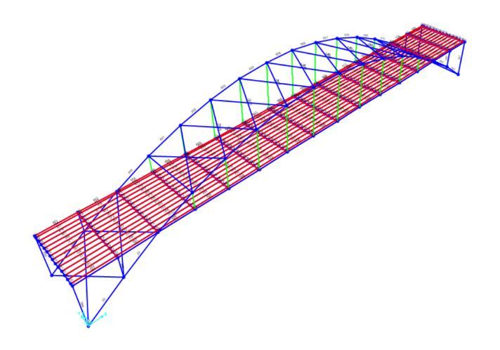
After optimizing rise modelling of bridges for different deckpositionwithoptimizedrise.
Comparisonofgenerateddataforallmodels
Resultsofthecomparativestudy&Conclusion.
TheSpanoftheBridgeis225m.
Span of Arch Bridge: Along-span bridge is decided to use, soa225-metrespanisconsideredforanalysis.Itmeetsthe long-span requirement and provides a clear length and numberofpanels.
Panel Arrangement: Panels should not exceed 1/15 of the bridgespan.Therefore,15panelswereprovided.
Arrangement of Hangers: Hangers are provided every 15 metres;theirheightcanbeobtainedfromthearcequation inthex-zpane.
WherefisthecrownofthearcandListhespanlength.
a. Y=f*[1-(2x/L-1)^2]Allowable Deflection- Highway bridges consisting of simple or continuous span should be designed so that deflection due to live plus impact load does not exceed 1/800th ofthespan.
For a bridge span of 225 m,only 28.12 cm of deflectionis allowableasperAASHTOcode.
The live load for a bridge consists of the weight of the appliedmovingloadofvehiclesandpedestrians.
International
Research Journal of Engineering and Technology (IRJET) e-ISSN: 2395-0056 Volume: 10 Issue: 07 | July 2023

LiveloadisconsideredaspertheAASHTOLRFDcode.The specificationofliveloading inthisstudy isHS20-44truck loading and a pedestrian load of 3.6 kN/m2. The applicationofthisloadingisshowninFig.1
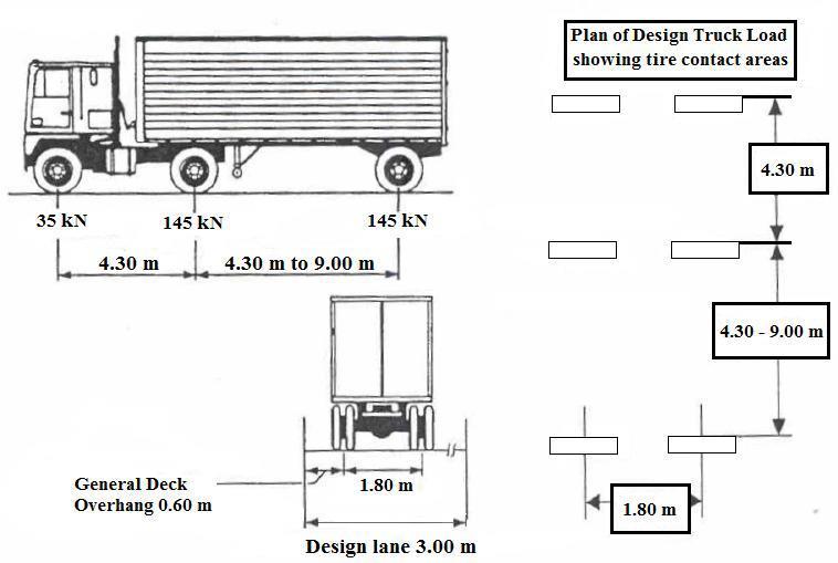
The weight and the spacing of axle and wheel for the designtruckshallbeasspecifiedinthefigure.
2.3 Modelling of bridges:
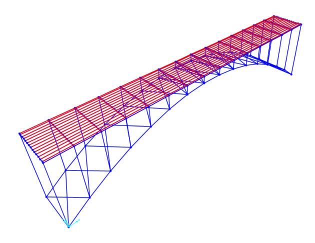
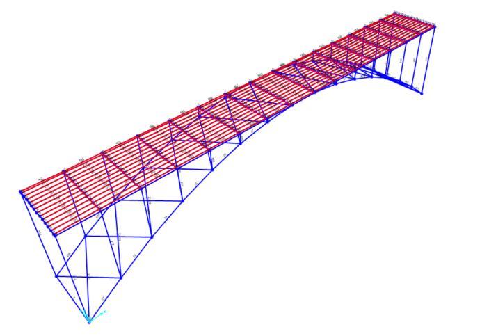
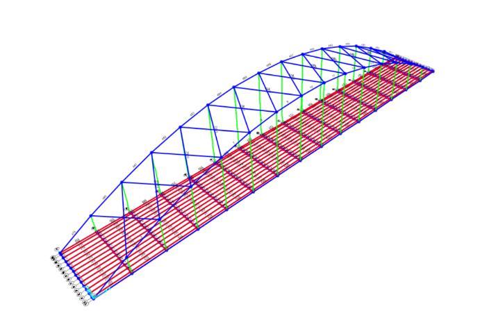
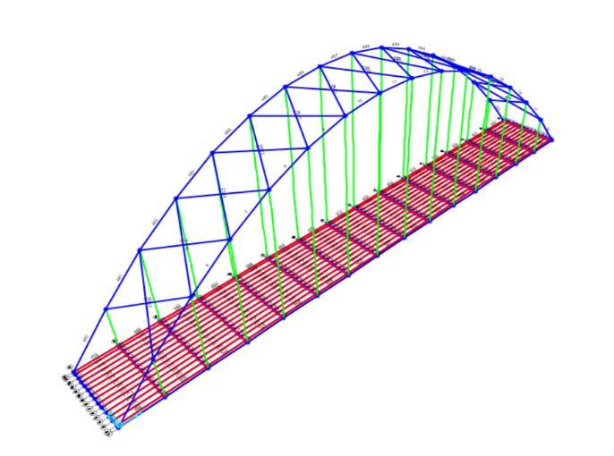
Optimizing Rise arch of bridge-
(sagging)bendingmomentstartincreasingwhenwemove tocenter.Maximummomentatthecentertobeobserved. Bending moments at a distance of 112.5m (at center) for modelsareasfollows:
Deflection: Deflectionstartsincreasingfromsupportand gets maximum value at the centre of the bridge. For the initial four models, deflection starts increasing with a decreasing rise arch. Last model no. 4 (L/6 = 37.5 m) crossedthedeflectionallowablelimit.
The allowable limit for deflection of the bridge is 1/800th ofthespanofthebridge(deflection<0.2818m).Deflection valuesforfourmodelsareshowninthegraph.
Cable height: ThecableheightdifferencebetweenL/3to L/6modelsis 18.75m>11.25m>7.5matcenterspanof bridge.Graphalsoshowthecableheightdifference.
Weight: TheweightdifferencebetweenL/3,L/4,L/5,and L/6modelsis86268kg>46295kg>21924kg,asshown inthegraph.
Deflection for different deck positions: Itwasobserved thatdeflectiondecreasedwhendeckpositionmovedfrom bottomtotop.Becausestructuresgetmorestiffbyadding spandrels. Maximum deflection is observed at the centre ofthespanofa through-typebridge;ineverynextmodel, deflection decreases, up to model no. 3 (deck-type bridge). Deck bridges give a minimum deflection of 16.43 cm. But in last model no. 4 (arch below deck), deflection started increasing. Deflection values for all models are showninthegraph.

International Research Journal of Engineering and Technology (IRJET) e-ISSN: 2395-0056

Volume: 10 Issue: 07 | July 2023 www.irjet.net p-ISSN: 2395-0072
Table -2: ComparingWeightanddeflectionforchangein risearchofbridge.
Chart -4: GraphRepresentingDeflectionofBridge.
Weight: Inanalysis,theweightofmodelsstartsincreasing as deck positions move upward. The minimum weight is observed in the fifth model (through-type bridge), and in every next model, the weight gets increased and reaches upto6430228kg.
Table -3: ComparingDeflectionandweightforchangein deckpositionofarchbridge.
Chart -5: GraphRepresentingDeflectionofBridge.
RESULT COMPARISON
Table -1: ComparingBendingMomentforchangeinrise archofbridge.
Sr. No. ModelName Bending Moment at distance of 112.5m.(centerofbridge) 1. L/3=75m 7078kN-m
L/4=56.25m 7639kN-m
8808kN-m
Inthisprojectsteelarchbridgeforatypicalspan225mis analysed for various structural position of deck and for different ratio of arch rise to span in the range 0.16 to 0.33.followingareconclusion.
When the rise of an arch decreases, the bending moment inthedeckofthebridgeincreases.
The rise of an arch decreases, deflection is found to be increasing.
The self-Weight of bridge decreases with decrease in rise tospanratio.
The allowable limit for deflection of the bridge is 1/800th ofthespanofthebridgeasperAASHTOspecification.
In L/5 rise to span ratio, weight is decreased by 2.12 % compare to L/3riseto span ratioanddeflection isalso in allowablelimitof1/800ofthespan,i.e<28.12cm.
RisetospanratioL/5issuggestedforuseinarchbridges because for this ratio bending moment is moderate, deflection is in allowable limit and the weight is less comparedtotheothermodels.
By comparing the different deck positions through type, semi-through type , deck tangential type and deck type bridge, it observed that when deck position moves from through to deck, deflection decreases but weight increases.
In deck position completely above arch both deflection andweightincreases.
In deck type bridge with rise ratio L /5, it was observed that reduction in deflection is 40.7% by only increasing 1.64% weight compared to through type bridge with rise ratioL/5.
To summarise by comparing all models, a deck-type bridge tangential to arch with a rise ratio of L/5 is more efficient. It meets requirement for low-weight structure andstabilitycriteria
[1] Anusha Bhasam, Tejaswini Akabilvam, “Design of chenabbridgeinindia”,July.-2021.
[2] Sunichi Nakamura, “Ultimate strength and chainReaction Failure of Hangers In Tied-Arch Brigdes” July-2020.
[3] XijuanJiang,“StaticandDynamicAnalysisofathrough TiedArchBridge”July-2019.
[4] DomenicoBruno,PaoloLonetti,“Anumericalstudyon network arch bridges subjected to cable loss” May2018.
[5] Dihang Ye, Xinhang Liu, Xun Wu, “Modeling and simulation analysis of special shaped arch bridge” , 2018.
[6] JielianZheng,“Concrete-FilledSteelTubeArchBridges inChina”,December-2017.
[7] Alessio Pipinato, “Structural analysis and design of a multispannetworkarchbridge”,2016.
[8] GeorgeLederman,ZhongYou,BrankoGlisic,“Anovel deployabletiedarchbridge”,2014.
[9] Arteaga, P. Morer, “The effect of geometry on the structuralcapacityofmasonryarchbridges”,2012.
[10] AASHTOLRFDCode
[11] D. Johnson Victor ,“Essentials of Bridge Engineering”
[12] .
[13] M. Young, The Technical Writer’s Handbook. Mill Valley,CA:UniversityScience,1989.
[14] R. Nicole, “Title of paper with only first word capitalized,”J.NameStand.Abbrev.,inpress.
[15] K.Elissa,“Titleofpaperifknown,”unpublished.
