Energy Auditing of Thermal Power plant
Mo’men AL-Tarawneh1 , Prof. M. Abu-Zaid 2
1 Graduate Student, Mechanical Engineering Department, Mutah University, Jordan

2Mechanical Engineering Department, Mutah University, Jordan ***
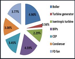
Abstract - The world and Jordan in particular, are facing the scarcity of fossil fuel sources on which it is mainly dependent forgeneratingelectricpower. Therefore, energy management and conservation in any power plant can be achieved through energy audit. In this study, a preliminary energy audit of a thermal power plant at Jordan phosphateminesindustrialcomplex wasconducted, that produce 14.36 MW at full load. This work evaluated the performance of power plant componentsandidentified required improvements based onenergylossbycomparing the design performance (reference) with the present performance (actual). The results showed a deviation in the present performance of all components for which the energy audit was conducted from the design performance. Percentages deviation of present efficiency from design efficiency of power plant components.as follows: FD fan efficiency 3.77 %, condenser efficiency 3.08 % and the biggest deviation was in boiler efficiency by 4.9%, because there was a poor quality of feed water and fuel, also the heat loss by flue gases and blow down. Several solutions have been proposed that contribute to improving the efficiency of the power plant.
Key Words: Thermal power plant; energy conserving; energy audit; efficiency.
Nomenclature
gGravitationalacceleration(9.8 ). H Head(m).
hSpecificEnthalpy(kJ/kg). hrhour.
Massflowrateofwater( ).
PPressure(bar).
QQuantityofsteamgeneratedperhour(kg/hr).
qQuantityofnaturalgasused( ).
Specspecificpowerconsumptionofpump( ).
TTemperature(℃).
1. INTRODUCTION
Oneofthemostimportantchallengesandproblemsfacing theworld,andJordaninparticular,isthedecreaseinnonrenewable energy sources and their depletion over time. Where there are two important points facing Jordan with regard to the issue of energy: the first point increased continuous demand on the energy and the other point limitedlocalresourcesandtheirinabilitytocoverthisgreat demandforenergy.Jordan'senergydemandisincreasingat arateof3%annually.Tomeettheseneeds,Jordanimports 94 % of fossil fuels such as oil and gas. Which causes a
violationofthestatetreasuryduetotheinstabilityoffuel prices. Therefore, the government decided to rely on renewable energy sources to provide 10 % of its energy needs, as electric power generation increased during the year2020from1.13GWto1.8GW.Therefore,energymust be well conserved and managed, so it is better to rely primarilyonrenewableenergysources[1].
ElectricityinJordanisgeneratedthroughconventional(nonrenewable) power plants and renewable energy plants of different generation methods. However, more reliance is placed on thermal power plants, which are conventional plants [2]. Where thermal power plant continuously convertstheenergyoffossilfuelssuchasoil,coalorgasinto mechanicalworkthenintheendintoelectricityenergy.It works by Rankine cycle, which includes four main components: boiler, turbine, condenser and pump. Total thermalpowerplantefficiencydependsontheefficienciesof thesecomponents.Wherethethermalefficiencyisasindex ofhowwelltheplantisexistenceoperatedascomparedto thedesigncharacteristics.
Energymanagementandconservationinanypowerplant can be accomplished by an energy audit. Energy audit is definedasasystematicproceduretoensureefficientuseof energywithmaximumefficiencybyidentifying,measuring andcontrollingareasof energyloss,aswell asidentifying alternativetechnologieswithintheirtechnicalandeconomic availability.Thereshouldbeaninclusivestudyandanalysis ofmanypartsofthepowerplanttoknowhowandwhere theenergyisusedandtochoosethemethodstosaveenergy, also provide solutions to reduce energy consumption. Energyauditworkstominimizetheamountofenergyinput intothesystembutitdoesnotaffectthepoweroutputofthe system.
Therearetwomaintypesofenergyaudit.Whereitclassified accordingtothedepthoftheauditingrequires,themethods usedtocollectthenecessarydata,theamountofcoststhat can be reduced and recommendations. In addition to, the timespenttocarryoutauditwhichdependsonthesizeof power plant. The first type is a preliminary energy audit (walk-through):thistypeissimpleanddoesnottakemuch time, may only need a few days. It largely depends on the availabledocumentsandashortvisittothepowerplant.It includesapproximately70%ofthetotalpowerplantandthe economic analyzes are limited. It is sometimes used to determinetheneedforadetailedaudit.Thesecondtypeis detailed energy audit this approach demands inclusive registration and analysis of energy consumption in all
componentsofpowerplantabout95%ofthetotalenergyis computed. Where many portable measuring devices are installed and they are the main approved source of data needed to conduct the audit, such as gas analyzer, digital manometers, digital thermometers, leak detector, etc. It containsanaccurateengineeringrecommendationandmust behaveapreliminaryenergyauditbeforeit.Whichtakesa longertimeandtheresultsaremoreaccuratecomparedto thepreliminaryaudit.
2. LITERATURE SURVEY
Thepurposeofthisworkwastoshowenergyauditingand energymanagementforboiler,turbine,condenser,coaland furnace..Theresultindicatethatintheboilerradiationloss happensbecauseofweakinsulationandtherewashumidity in coal Led to loss in wet and dry stack about 6.10 % and 5.13 % respectively. The problem was in turbine due to leakage of air and inflow gasses, and lifespan of turbine blades depressed because of the amount of oxygen that enteredtheturbinethroughmakeupwateristhewaterthat isaddedtorecoverforlossessuchaslossesresultingfrom evaporation, but the condenser faced a reduction in condenserspaceabout0.025kg/ aresultofinsufficient quantity of cooling water, unclean pipes and air losses, in addition, there was a difference in hot well temperature betweenactualanddesigned33and44,respectively.With regardtothefurnaceshowedthatdecreaseinperformance duetotheradiationwastewasabovefrom6%[3].
Thisstudyshowedmethodsthatenhancetheefficiencyofa steam power plant by raising the parameters of steam at inletturbine,asplantsthatproducesteamat(25MPa,600 °C)are3%moreefficientthanthesurroundingareasthat producesteamat(30MPa,566°C).Alsothroughreduction theparametersofsteamatoutletturbine,astheefficiency increasedby2.2%whenreducingexhaustpressurefrom6 KPa to 4 KPa. The third method is the pre heating of the feedwater,whichusesheatfromextractingsteamfromthe turbine,14althoughwhenincreasingthepre-heatingstages leads to an increase in the efficiency of the plant, but it increasesthecostofestablishingtheplant[4]
Inanotherstudy,itwasfoundthattheperformanceofthe componentsdecreaseswithreducingtheload,exceptforthe boiler.Alsotheoverallefficiencyatloaddropfrom250MW to125MWdecreasedfrom38.5%to34.63%.Wherethe main energy losses were in the condenser and turbine generator.Although the boilerefficiencyislowerthanthe design, it is satisfactory. One of the most important recommendationsmadeisthatthestationshouldoperateat thehighestloadinordertoimproveefficiency,reducethe temperatureofthefluegasestotheminimumpermissible, cleanthecondensertubes,improvetheperformanceofthe coolingtower,improvethedesignoftheturbinebladesand checksealsintheturbine[5].
3. DESCRIPTION OF THERMAL POWER PLANT

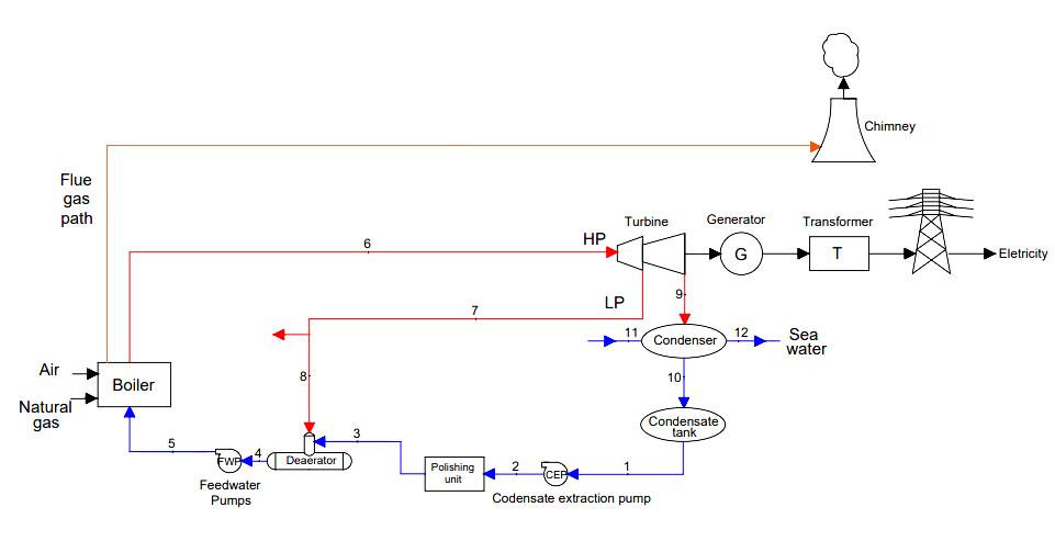
The thermal power plant at Jordan phosphate mines industrialcomplexislocatedintheGulfofAqaba,southof Jordan,about18kmfromthecitycenternearthebordersof the Kingdom of Saudi Arabia. The power plant produces 14.36 MW works by Rankine cycle. The fuel used for the combustionprocessintheboilerisnaturalgas.Figure3.1, shows the power plant components through schematic diagram. Also the Table 3.1, displays the thermodynamic properties of working fluid at each point on schematic diagram. The properties of natural gas and air are also presentedinaTable3.2.
Fig 3.1 Schematicdiagramofthethermalpowerplant. Table 3.1: 1showsthepresentthermodynamicproperties oftheworkingfluidateachpointonSchematicdiagramof thethermalpowerplantat100%

Thetypeofboilerusedinthethermalpowerplantiswater tubeboilerD-shape.Thefeedwaterflowsthroughthetubes and is heated by the hot gases surrounding these tubes. Thesegasesareproducedbyburningnaturalgasinsidethe furnace. The boiler design specifications are available in a Table 3.11. Major parts of this boiler are water wall tubes, steamdrum, water(mud)drum,super heater, economizer andfurnace
thatthemovingbladesmoveinareversaldirectiontothe steam then the rotor rotates. This process is called a reactionaccording to Newton's third law, but during the moving blade decreases velocity and pressure. When steam exitsfromthemoving bladesinthefirststage,itis directedfromthe fixed blades to enter the moving blades in the secondstage,inthiswaythesteampathcontinuesin the turbine [6]. The turbine design specifications are presentedintheTable3.2.1.
Steamturbineisoneofthemostimportantcomponentsof the power plant. It is a rotating mechanical device that produces mechanical work by converting thermal energy containedinthesuperheatedsteamtokineticenergy.This mechanical work rotates the shaft connected to the generator to produce electrical energy. The type of steam turbineinstalledinthispowerplantisareactionturbine.It has two stages the high pressure and low pressure stage, wheretheeachstagehasoneoutletattheendofthestage only.
The reaction turbine consists of a set of fixed and moving blades arranged in rows. Where steam flows over both blades(fixedandmoving).Thefixedbladesactasanozzle, sothepressuredecreasesandthevelocityincreasesdueto theexpansion,thenthekineticenergyincreases,andaforce isgeneratedoppositetothedirectionofthesteamflowso
Thetypeofcondenserinstalledinthisplantisanindirect condensertype.Whereitisknowsasaheatexchangertubes andwatershell.Heatistransferredfromsteamtocooling waterwithoutmixingthemwitheachother(indirectly),to convertexhauststeamtoliquidstate.Atapressurelessthan atmosphericpressure.Itsmainpartsareinletboxofwater, outletboxofwater,tubesofwater,shellisacylindricaland closed at both ends, made of cast iron, tube sheet whose function is to install water tubes, hot well is installed at bottom of shell to ensure that the fluid transferred to the pumpisliquidwater.Thispartisnotinsulatedinorderto loseitsheattotheatmospheretoobtainwaterisstateasub cooled,andthereareairpipesinstalledattopthecondenser that connect with ejector nozzle and ruptured disc that opens when the condenser pressure exceeds atmospheric pressure to balance them[6]. The condenser design specificationsareavailableinaTable3.3.1

It is a centrifugal fan that is installed near the boiler to supplytheamountofair(oxygen)requiredforcombustion tooccurwheretheairpressureinsidethe boilerishigher thantheatmosphericpressure,whichoperatedbyelectric motor.Thedraftmeansthatthereisadifferencebetween the pressure inside the furnace in the boiler and the atmospheric pressure [7]. The forced draft fan design specifications and present values are available in a Table 3.4.1

Themaincomponentinthepowerplantthroughwhichthe Rankinecyclebeginstooperate,itsuppliestheboilerwith the working fluid (water) in the required conditions. It is necessary that these pumps operate with a very high capacityandreliability,becauseanydamagethatoccursto themleadstoadefectinthegenerationofsteam.Thereare threehorizontalcentrifugalpumpmultistage(sevenstages) inordertoprovideadequateofpressureandhead,thatwork by electric motor. With regard to the boiler feed pumps design specifications and present value are available in a Table3.5.1.
3.6 Condensate extraction pump (CEP)
Thistypeofpumpisusedtoextractthewaterresultingfrom thecondensationofsteaminthecondenserandthereturnof hot water. This power plant has single stage vertical condensate extraction pump. The main functions of this pump are extract water and transfer it to the deaerator through the polishing unit without an obvious increase in pressure. The condensate extraction pump design specificationsandpresentvaluesarepresentedinaTable 3.6.1.
3.7.Deaerator
TheobjectiveofDeaeratorareremovethedissolvedgases (oxygen and carbon dioxide) and the gases that are not dissolvedinthewater,topreventtheoccurrenceofoxideson the walls of pipes and metal parts due to the presence of oxygeninthewaterandreducetheoccurrenceofcorrosion due to carbonic acid resulting from the reaction of carbon dioxidewithwater.Thetypeofdeaeratingdeviceisthetray type, which consists of a vertical cylinder that includes the deaeration process and is mounted on a large horizontal cylinderasafeedwaterstoragetank.
4. Theoretical Analysis

Thissectionshowsalltheequationsandcalculationsusedto conducttheenergyauditofthepowerplantaccordingtothe AmericanSocietyofMechanicalEngineers(ASME).Withthe progressoftime,thisASMEhasdevel
opedmanystandardized andconsistentmethodscalledperformancetestcodes(PTC) to audit and test all the major parts in a power plant that couldbeamajorcauseofenergyloss.

4.1. The Boiler
BasedonASME(PTC4-1998),thedirectmethod(inputand outputmethod)wasadoptedtoevaluatetheperformanceof theboiler.Theformulaofthedirectmethodis: Or

4.2 The Turbine
Based on ASME (PTC 6 -1996), the turbine performance evaluatethrough:
Heat rate, where it is the ratio between the heat enteringthecycleandtheelectricalpowerproducedby thegenerator,whichshowshowmuchheatenergyis neededtogenerate1kWhofelectricity.Theheatrate inverselyproportionaltotheefficiencyoftheturbine cycle.Itisexpressedmathematicallyas:
Turbinecycleefficiencywhichisdefinedasefficiency ofsteamturbinegeneratorisexpressedas:
Theisentropicefficiencyofsteamturbineisimposing that the flow during turbine is isentropic to produce isentropic work, and then it defined the deviation actualworkfromisentropicwork.Definedas: Or
4.3 The Condenser
Thethermalefficiencyofthecondenserrepresentstheratio betweentheactualtemperatureriseofthecoolingwaterand themaximumpossibletemperaturerise..Toestimatethis efficiency, the convenient standard according to ASME is PTC12.2–1998.Itisexpressedasfollows:
4.4
Thepresentdataneededtoperformtheenergyauditforthe performanceofthesepumpsareshowninTables(4.4.1and 4.4.2).Thestandardrequiredtocalculatetheperformance ofcentrifugalpumpsisPTC8.2–1990.Asfollows:

Hydraulicpower(kW)=
Pumpefficiency
Theformulaforcalculatingthespecificpowerconsumption ofpumpsisasfollows:

TheperformanceofForceddraftfanhasbeenevaluated,by the ASME (PTC 11-1984). The present data related to conductinganenergyaudittoforceddraftfanisavailablein table(3.14.5.12)asfollows:
4
The deaerator performance has been calculated by the terminal temperature difference (TTD), which is the differencebetweenthesaturationtemperature( )ofthe interruptingpressureofsteamflowingfromthefirststageof steamturbineandthetemperatureofthewaterleaving it ( )ThroughtheASME,thestandardthatshowsdeaerator performanceisPTC12.3-1997.Theterminaltemperature differenceisasfollows:
5. Results and discussion
The results showed a deviation in the performance of all componentsofthepowerplantforwhichtheenergyaudit was conducted from the design performance as shown in Table5.1andFigure5.2.Withrespectthecycleefficiency, theefficiencyslightlydecreasedfrom22.2%to21.7%.The overallefficiencywas17.9%,butthedesignefficiencywas not available. The boiler efficiency was 82.1 % while the design efficiency was 87 %. The reasons that reduce the performanceoftheboilerarepoorqualityoffeedwaterand fuel,increasedheatlossbyfluegasesandblowdown,also heat loss due to poor insulation (loss by convection and radiation),aswellascontrollingthequantityandqualityof airflowingintotheboiler.
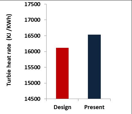
Regarding turbine performance, attention was paid to turbine heat rate, turbine generator efficiency, and isentropicefficiency.Theresultsshowedthatthevaluesare the following: 16530.8 kJ/ kWh, 21.8 % and 69.8 % respectively. Against the design values 16119.2 kJ/ kWh, 22.3 % and 72.1 % respectively. Turbine heat rate which inversely proportional to the efficiency of the turbine increasedby411.6kJ/kWhoverthedesignvalue,whichled toadecreaseintheturbineefficiencyasshownintheFigure 3. Where the main factor in turbine efficiency is the temperatureofthesteamflow.Afteranalyzingthedata,it wasobservedthattherewasadecreaseinthesteamflow temperature by an average of 5 °C from the design temperature.Ithasbeenproventhattheturbineheatrate increases by 0.5 % when the steam flow temperature decreases by 10 °C. Also, the turbine blades must be maintainedregularlytoensuretheintegrityofthesealsand deposits on the blades, where stress corrosion and imbalanceoccurduetosaltandsilicondeposition.Aswellas theoccurrenceofroughnesstothesurfaceoftheblades.The performanceoftheturbinebecomesworseintermsofheat rateby1%whenthesurfaceroughnessofthebladesis10 μm[8].


The performance of BFPs in terms of hydraulic power, combined efficiency and pump efficiency were 145.5 kW, 58.7%and68.3%respectively.Butthedesignvalueswere 148.3kW,63.38%and72.9%respectively.Also,therewas an increase in the specific power consumption by 0.2 kWh/ .BFPsareworkedatawaterflowrateclosetotheir design but there is a gap in total head and discharge pressure. Concerning the performance of the condensate extraction pump, the hydraulic power was 31.18 kW, the combinedefficiencywas69.3%andthepumpefficiencywas 77.854%.Whereasthedesignvalues32.2kW,74.8%and 81.3 % respectively. Although there is an increase in the specific energy consumption of 0.04 kWh/m³, it is satisfactory. Continuous operation of the pump leads to increasedsurfaceroughnessandmechanicallossesrelated tosealsandbearings.Inadditiontoimpeller-relateddefects.
The condenser efficiency was found to be 39.3 %, but the designefficiencywas42.4%.Therewasadifferenceinthe temperatureofthecoolingwaterwhenenteringandexiting thecondensercomparedtothedesign.Itispossiblethatthe condensertubesarenotclean,andthenseawaterthatused for cooling is dirty and not treated properly. The performance of the FD fan decreased, where its efficiency was78.4%,incontrast,andthedesignefficiencywas82.2 %. There is a decline in airflow by the FD fan versus the designvalue.
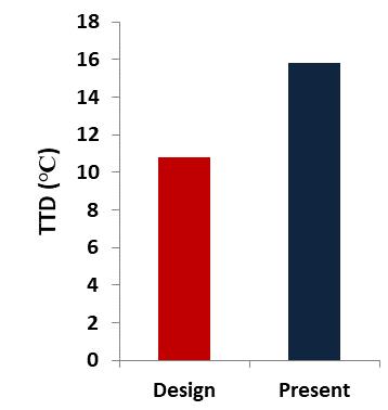
Theindicatorusedfortheperformanceofthedeaeratorwas theterminaltemperaturedifference(TTD).Through[6]it was found that TTD is an indicator of heat transfer in the deaerator,astherelationshipbetweenthemisinverse.Ifthe TTDvalueincreases,theheattransferdecreases,whichisa negativeindicatorofdeaeratorperformance.Afteranalyzing the results, it appeared that there was an increase in the value of TTD. Where it reached to 15℃, while the design valuewas10.8℃asintheFigure4.Therewasanincreasein steampressureby40kPa,whichledtoanincreasein , andadecreaseinthepressureofcoldwaterenteringby170 kPa, accompanied by a decrease in water temperature, which affected the properties of the water leaving the deaerator.Also,thereasonsforthedecreaseinperformance are vent of deaerator head not open enough because of calcificationwhichleadstobackpressureindeaeratorsothe mass flow rate of inlet steam decrease, and level of deaeratortanknotaccuratewhichcausestoincreasemassof waterintanksothetemperatureofwaterdecrease.
After analyzing the results, there are many solutions that help to improve the performance of the power plant, as follows:


Installationanairpreheaterattheboilerairinlet.It isaheatexchangerthatheatstheairenteringthe boilerbyexchangingheatbetweentheairandthe hot flue gases, the temperature of which drops before it reaches the chimney. Preheating the air helps to speed up the combustion process inside thefurnacesothatanefficientcombustioncanbe obtained. In addition, it reduces the cost of the steam generation process. When the air temperature rises by 4.4 ℃, the boiler efficiency increases by 1 %. Also, each decrease in the temperatureofthefluegasesby20°Ccorresponds toanincreaseinboilerefficiencyby1%[9].
To improve efficiency of the plant in general and the performance of the turbine in particular, it is necessary to increase the temperature of steam flowingtotheturbineandreducethetemperature ofthesteamleavingtheturbine,aspossible.Thisis donebyinstallingafeedwaterheaterthatreduces fuel consumption rate and heat rate, and thus reduces steam 65 generation cost and environmental influences[10]..Also, regular maintenanceshouldbedonetotheturbineblades.
Checking the quality of fuel (natural gas) and regulating the air flowing at the combustion chamberbycontrollingthe quantity of excessair. Togetacompletecombustionandreduceemission

6. Conclusions
The energy audit helps to know the performance of the power plant components and determine how much improvementtheyneedbasedonthegapbetweenpresent anddesignvaluesthatoccurduetoenergylossandalsoto learn about energy conservation methods. The thesis showed, by conducting an energy audit for this plant that after a period of time on the operation of plant, the performance of the main and auxiliary plant components decreases,somonitoringandperiodicmaintenanceshould becarriedouttoconserveenergyandreducethecausesof loss.Afteranalyzingtheresults,themainconclusionsareas follows:
Thecycleefficiencyslightlydecreasedfrom22.2%to 21.7%,andtheboilerefficiencywas82.1%whilethe designefficiencywas87%.
The turbine heat rate increased by 411.61 kJ/kWh morethanthedesignvalue,whichledtoadecreasein turbineefficiency.Because ofdecreaseinthesteam flowtemperatureandoccurrenceofroughnessonthe surfaceoftheblades.
Regardingtheperformanceofcentrifugalpumps,the BFPefficiencydecreasedfrom72.9%to68.3%and theCEPefficiencyreached77.9%butthedesignvalue of81.3%.
Thecondenserefficiencywasfoundtobe39.3%,but thedesignefficiency was42.4%.TheFDfan hadan efficiency of 78.4 %, whereas the design efficiency was82.2%.
Theresultsshowedthatthelargestdeviationbetween the present performances from the design performance of the power plant components that havebeenauditedwastheboilerby4.9%.
Whentheboilerefficiencyisincreasedby2%then thenaturalgassavedat2%equals137.86 /hrand the total natural gas saved per year equals 1207.7* . In addition to reducing the consumption of natural gas per year by 2415. 31* whenapplyingthereheatsystem.
ACKNOWLEDGEMENT
I extend my thanks to the management of the Jordan Phosphate Mines Company for their cooperation with me duringthecollectionoftherequireddata.
REFERENCES
[1] Abu-Rumman, G., Khdair, A. I., & Khdair, S. I. (2020). Current status and future investment potential in
renewableenergyinJordan:Anoverview.Heliyon,6(2), e03346.https://doi.org/10.1016/j.heliyon.2020.e03346.

[2] CEGCOANNUALREPORT.(2018).
[3] Singh, P., Suman Bhullar, M., & Paragnijhawan, M (2012).EnergyAuditingofThermalPowerPlant.
[4] Zhang,T.(2020).MethodsofImprovingtheEfficiencyof Thermal Power Plants. Journal of Physics:Conference Series, 1449(1). https://doi.org/10.1088/17426596/1449/1/012001.
[5] Patel, S. S. L., & Agrawal, G. K. (2017). Performance ImprovementThroughEnergyAuditofa250MwCoal Fired Thermal Power Plant. International Journal of AdvanceEngineeringandResearchDevelopment,4(04), 35–43.https://doi.org/10.21090/ijaerd.77633
[6] Saravanan. (2012). OPERATION. Thermax training centre,trichy.
[7] ERFORMANCE,P.,&STIMATES,C.O.S.T.E.(2009).N EWCOAL-FIREDPOWERPLANT.
[8] Khushalani, B. (2004). Energy audit of a 1100 MW power plant. Collection of Technical Papers - 2nd International Energy Conversion Engineering Conference,3(August),1971–1980.
https://doi.org/10.2514/6.2004-5771
[9] Index Boiler Operations | CleanBoiler.org. (n.d.). from http://cleanboiler.org/learn-about/boiler-efficiencyimprovement/efficiency index/index-boileroperations/.
[10] Oyedepo,S.O.,Kilanko,O.,Waheed,M.A.,Fayomi,O.S.I., Ohunakin, O. S., Babalola, P. O., Ongbali, S. O., Nwaokocha,C.N.,Mabinuori,B.,&Shopeju,O.O.(2020). Datasetonthermodynamicsperformanceanalysisand optimization ofa reheat – regenerativesteamturbine powerplantwithfeedwaterheaters.DatainBrief,32, 106086.
