International Research Journal of Engineering and Technology (IRJET)

Volume: 10 Issue: 07 | July 2023 www.irjet.net
e-ISSN:2395-0056
2395-0072
STRUCTURAL BEHAVIOUR OF CURVED BOX GIRDER BRIDGE
Shivani S. Kolhe1, Dr. M. R. Shiyekar21M- Tech student, Applied Mechanics Department, Govt College of Engineering, Karad
2Professor, Applied Mechanics Department, Govt College of Engineering, Karad ***Abstract: Curved box girder bridge is extensively used in metro rail bridges. It is vital to build bridge constructions with curved plans as horizontally curved alignments for railway bridges and urban interchanges are becoming more common. Torsional moments are mostly present because of the influence of the box girders' horizontal curvature. This study's primary goal is to evaluate the analytical results of horizontally curved box girder bridges having different parameters. In this paper, the numerous models for curved box girders are analyzed using MIDAS software for different parameters such as span lengths, radius of curvature, and loadings. The results obtained are in terms of shear force, bending moment, torsional moment, and midspan deflection. It is observed from the results that there is no significant change in bending moment and shear forces for each radius of curvature but with increasing Radius of curvature there is an appreciable decrease in the value of torsional moment.
Keywords:- Curvedboxgirders;prestressedconcrete;Torsionalbehaviour;mid-spandeflections;finiteelementmethod, MIDASSoftware.
1. INTRODUCTION
Curved box girder bridge is used in metro rail bridges and highway bridges. It is made up of structural steel, reinforced concrete, or pre-stressed concrete and the box is a single-cell, double-cell, multi-cell, and multi-spine with rectangular, circular,ortrapezoidalincross-section.Inboxgirderbridgesthegirdersisintheformofhollowboxsection.Itcanalsobe usedforvariouspurposessuchaselectricsupplylines,telephonecables,watersupplylines,sewers,etc.andtheboxgirder sectionhastheadditionaladvantagethatitislighterinweight.InthecurrentspecificationsoftheIndianrailwaycode,no separate guideline is available for the curved box girder bridge except for consideration of torsional moment. There are various methods available for the analysis of box girders such as the orthotropic plate theory method, folded plate method, grillageanalogy method, finite strip method, finite element method, computer programming & experimental studies. H. Zuwei et al.[1] used grillage analogy method for multi-cell box girder with transverse slope B. Al-Masoud et. al[2]usedfoldedplatemethodfortheanalysisofroofsandcellularbridgesandcomparetheresultwithvariousmethods
W. Feng et. al.[3] developed finite strip method to analyze the Single Cell Curved Box Girder Bases. C. P. Heins et al.[4] developed a program for the analysis of simple or multi-span composite or non-composite steel box girder bridges
R.Shreedharet. al.[5]performedaComparativestudyoftheGrillagemethodandFEMmethodoftheRCCBridgeDeck K. Shushkewich[6]hasdevelopedanapproximateanalysisofaconcreteboxgirderbridgebyusingafoldedplate,finitestrip, andfiniteelementmethodbyusingsomesimplemembrane equations.N.Guptaet.al.[7]AnalyzedRCCcurvedboxgirder bridges by using a finite element approach. S. Gajera et. al.[8] performed a Parametric Study of Horizontally Curved PreStressed Concrete Continuous Box Girder Bridges. A. Sarode et. al.[9] analyzed the Torsional Behavior and Constancy for Horizontally Curved Box Girders. D. B. Kulkarni et. al.[10] performed Dynamic analysis of RCC curved beam using the software. R. Jain et. al.[11] performed Stability analysis and Torsional Behavior of Horizontally Curved Box Girders. K. M. Sennah et. al.[12] investigated approximate and conservative methods for the analysis and design of straight and curved boxgirderbridges.A.S.Khairmode[13]AnalyzedthePrestressedConcreteMulti-CellBoxGirderCurvedBridge.M.Pathak [14] used SAP software for presenting several behaviours for horizontally curved RCC box bridges. R Jaiswal et. al.[15]Analyzedthe elevatedMetro Bridge as per IRC 70R loading and it can be done by using STAAD.Prosoftware.
Inthispaper,numerousmodelsareanalyzedfordifferentparameterssuchasradiusofcurvature,spanlength,andvarious loadings. Torsional moments predominate because of the horizontal curvature of the box girders. Also due to loading, more deflections are occurred at mid-span. Hence the flexural behaviour, torsional behaviour, stability, and mid-span deflectionsofthecurvedboxgirdersofdifferentparametersarediscussedinthispaper
2. SCOPE OF THE STUDY
a) To analyze the three-dimensional finite element models of the Box girder for different parameters such as span length,theradiusofcurvature,depthoftheboxgirderunderMetrorailwayloadings
International Research Journal of Engineering and Technology (IRJET) e-ISSN:2395-0056

Volume: 10 Issue: 07 | July 2023 www.irjet.net p-ISSN:2395-0072
b) Tocomparethevariationofbendingmoments,torsion,andshearforceduetochangesintheRadiusofcurvature.
c) Tofindvariationindeflectionsatthemid-spanoftheboxgirderandtwistofthecross-section.
3. METHODOLOGY
AparametricstudyofcurvedPrestressboxgirderisundertaken.Forstudypurposes,a20m-45mspanofbridgecurvedin plan is considered. single cell Rectangular Curved box girder with Prestressed configuration is considered. Parameters such as span, and curvature are varied, and span to depth ratio is constant for analysis, effects of these changes on the shearforce,torsionalmoment,bendingmoment,anddeflectionarecarriedout.
3.1 Design Consideration -
SpanLength=20m
Deckwidth=9.6m.
TheradiusofCurvature= = =75m
SpantoDepthRatio=16
ModulusofElasticityE=35.355×10⁹ N/m2
Densityρ=2400kg/m3
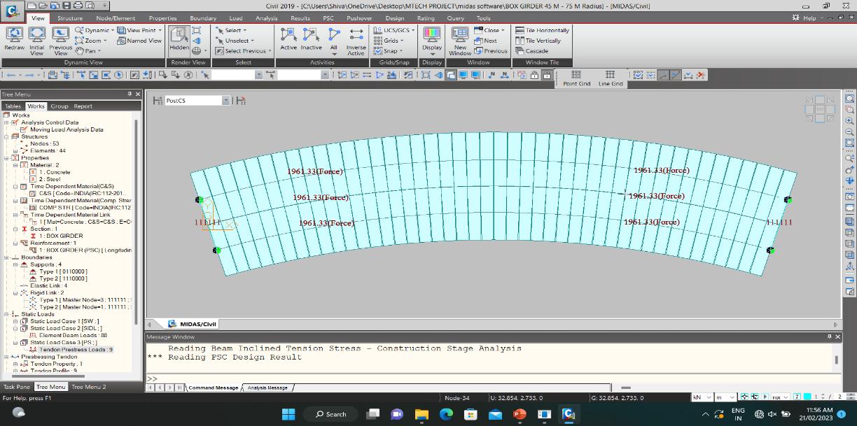
Nineprestressedtendonsarelocatedatthegirdersoffit.
Themodulusofelasticityforthetendonsis200×109 N/m2
3.2 Design Load
TheLoadingconsideredintheanalysisare–
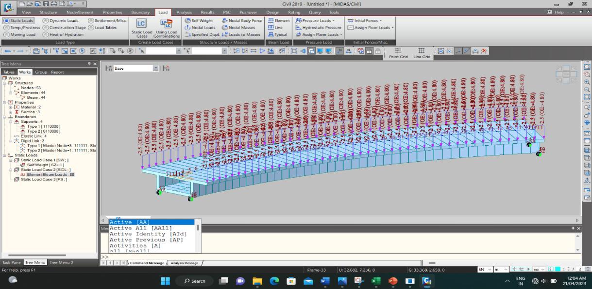
A. Self-weight (DL) of box girder: - A dead load of different components of the superstructure is considered by usingastandardunitweightbasedontheIRScodeprovisions.This includestheself-weightofthedeckslaband girders.
B. Superimposed dead load (SIDL) form crash barriers and wearing coat: - the elements which are taken into considerationforcalculatingsuper-imposeddeadloadsuchasCables,Handrail,Parapet,CableTrays,TrackPlinth, Miscellaneous(E&M)RailandPad,etc.
C. Live Load (LL): - Live Load (LL) is taken as per the IRS CBC Loading. DFC Combination-1 for Broad Gauge is considered.TheappropriateimpactfactorsasperIndianRailway Standardsareappliedtoliveloadfordifferent spanlengths.
4. FINITE ELEMENT MODELING AND ELEMENT DESCRIPTION
For finite element modeling MIDAS Software is used. For all kinds of linear and nonlinear stress, dynamic, and thermal/fieldissues,theMIDASsystemutilizesfiniteelementanalysistechniquestodeliverexactsolutions.Thestudyof the specified problem is performed by the effective finite element analysis usingMIDAS Civil software. The thick shell surface geometry is used to simulate the box girder's components, which are then discretized by creating a mesh of elementswithfournodes,thicknesses,andmaterialpropertiesspecifiedperIRSCBC1997.[16].


5. RESULTS AND DISCUSSION

Thehorizontallycurvedboxgirdersofspanlengths20mto45mwitharadiusofcurvature75m,100m,200m,and300m. Atotal of24modelsareanalyzedusingthe finite elementanalysismethod.MIDAS civil softwareisusedtocarryoutthe analysisandtheresultsfortorsionalmoments,mid-spandeflectionsbendingmomentsandshearforcesthe reactionsfor DeadLoad,Super-imposedDeadLoad,andLiveLoadarepresented.
a) Variation in torsion, bending moments and shear against span radius. Themaximumtorsion,bendingmoments,andshearforcesforvariousspanlengthsandradiiarecompared.
Fig.VariationinTorsionforvariousspanlengthsandradii
Fromtheabovefigures,itisobservedthatthereisnosignificantchangeinbendingmomentsandshearforcesforaspan withdifferentradii,butthetorsionalmomentsvarygreatlyduetothecurvatureeffect.Thereisatremendousincreasein torsionwithdecreasingspanradius.
b) Mid-span deflections
ThemaximumMid-spandeflectionforvariousspanlengthsandradiiisshownbelow.
Fig.VariationinMid-spandeflectionforvariousspanlengthsandradii
Due to the radius of curvature, a torsional moment occurs. The torsional moment caused the deflection at mid-span is more as compared to other locations. It can be observed that mid-span deflection increases with increasing span length anddecreasesinspanradius.
6. CONCLUSIONS

In this paper numerous curved box girder superstructure models are analyzed for the various parameters such as span lengths, the radius of curvature, and loading are carried out using MIDAS Finite Element Analysis software to access the more accurate bending moments, shear, torsion, and mid-span deflections. The following are the findings of this investigation
1. It can be observed that there is no significant change in bending moment and shear forces for a span length for differentRadiusofcurvatures
International Research Journal of Engineering and Technology (IRJET) e-ISSN:2395-0056

Volume: 10 Issue: 07 | July 2023 www.irjet.net p-ISSN:2395-0072
2. Thetorsionalmomentincreasesremarkablywithadecreaseintheradiusofcurvatureoftheboxgirder.Also,the torsional momentincreases witha decrease inspanlength.Significantchangecan beseenintorsional moments whentheradiusisbelow200mandfewervariationsareobservedastheradiusincreasesabove200m.
3. Itisobservedthatthereareconsiderablevariationsinthemid-spandeflectionofcurvedboxgirderbridge
4. Itcanbeobservedthatmid-spandeflectionisinnegativecorrelationwithradiusofcurvatureMid-spandeflection increaseswithadecreaseinradiusofcurvatureandanincreaseinspanlength.
7. REFERENCES
[1] D.Huang,“Full-ScaleTestandAnalysisofaCurvedSteel-BoxGirderBridge,” J. Bridge Eng.,vol.13,no.5,pp.492–500,Sep.2008,doi:10.1061/(ASCE)1084-0702(2008)13:5(492).
[2] B. B. Al-Masoudy and L. K. Al-Hadithy, “Analysis techniques for folded plate roofs and cellular bridges general review and comparisons,” IOP Conf. Ser. Mater. Sci. Eng., vol. 518, no. 2, p. 022060, May 2019, doi: 10.1088/1757899X/518/2/022060.
[3] X.Lei,H.Jiang,andJ.Wang,“TemperatureEffectsonHorizontallyCurvedConcreteBox-GirderBridgeswithSingleColumnPiers,” J. Aerosp. Eng.,vol.32,no.3,p.04019008,May2019,doi:10.1061/(ASCE)AS.1943-5525.0000992.
[4] C.Yoo,J.Buchanan,R.M.P.Company,C.P.Heins,andW.L.Armstrong,“ANALYSISOFACONTINUOUSCURVEDBOX GIRDERBRIDGE,”p.11.
[5] R. Shreedhar and R. Kharde, “Comparative study of Grillage method and Finite Element Method of RCC Bridge Deck,”vol.4,no.2,2013.
[6] K.W.Shushkewich,“ApproximateAnalysisofConcreteBoxGirderBridges,” J. Struct. Eng.,vol.114,no.7,pp.1644–1657,Jul.1988,doi:10.1061/(ASCE)0733-9445(1988)114:7(1644).
[7] N.Gupta,P.Agarwal,andP.Pal,“AnalysisofRCCcurvedboxgirderbridges,”vol.1,2019.
[8] Dr. V. R. Panchal Satish Gajera, “PARAMETRIC STUDY OF HORIZONTALLY CURVED PRE-STRESSED CONCRETE CONTINUOUSBOXGIRDERBRIDGES,” Int. J. Adv. Eng. Res. Dev.,vol.4,no.04,Apr.2017,doi:10.21090/IJAERD.CE027.
[9] A. B. Sarode and G. R. Vesmawala, “Parametric Study of Horizontally Curved Box Girders for Torsional Behavior andStability,”p.6.
[10] D. B. Kulkarni and N. S. Ingawale, “Dynamic Analysis of a Reinforced Concrete Horizontal Curved Beam Using Software,” Int. J. Res. Eng. Technol.,vol.04,no.04,pp.557–560,Apr.2015,doi:10.15623/ijret.2015.0404096.
[11] R. Jain, M. A. Singh, and P. Student, “Parametric Study of Horizontally Curved Box Girders for Torsional Behavior andStability,”p.5,2016.
[12] K.M. Sennahand J. B. Kennedy, “LiteratureReview inAnalysisofBox-GirderBridges,” J. Bridge Eng., vol.7, no. 2, pp.134–143,Mar.2002,doi:10.1061/(ASCE)1084-0702(2002)7:2(134).
[13] A. S. Khairmode and D. B. Kulkarni, “Analysis of Prestressed Concrete Multi-cell Box Girder Curved Bridge,” Int. J. Sci. Res. IJSR,vol.5,no.6,pp.2455–2459,Jun.2016,doi:10.21275/v5i6.ART20162.
[14] M.K.Pathak,“PerformanceofRCCBoxtypeSuperstructureinCurvedBridges,”vol.5,no.1,p.10,2014.
[15] Prof.L.T.RajatJaiswal,“DesignofElevatedMetroBridge,” Int. J. Adv. Res. Sci. Commun. Technol.
[16] “IRSCBC1997-Codeofpracticeforplain, Reinforced&Prestressedconcrete forgeneralbridgeconstruction.”
