“Comparative Study of G+16 Building Regular and Irregular buildings Design with Shear wall and without shear wall in E-TABS for Zone-3”
Harish babu Aluri, M. Ramachandra Rao1 P.G. Student, Department of Civil Engineering, NRI Institute of technology, Vijayawada, Andhra Pradesh ² Assistant Professor, Department of Civil Engineering, NRI Institute of technology, Vijayawada, Andhra Pradesh

Abstract - TheprimarygoalofthisprojectistouseETABS to analyze and design. “Comparative study of G+16 building regular and irregular buildings design with shear wall andwithoutshearwall inE-tabsfordifferent seismic zones Thisworkconsidersthreezonesandthree soiltypesforallfourzones,thoughIonlyworkedonsome. Medium-type soil is one of those zones, and medium-type soilisoneofthosesoiltypes.Whenitcomestoanalyzingand designingstructures,thisistheonlyapplicationthatcomes close to ETABS (Extended Three-Dimensional Analysis of BuildingSystems).
Nowadays,constructions of highraised buildings, majorproblemsarefacingseismiceffectandwindeffectis difficulttodesignforstructuralengineers.Thisearthquake resistancedesignmainlydependsontypesofstructuresand zoneofbuilding.Thislateraleffectscompletelyresolvedby usingshearwalldesignbothregularstructuresandirregular typeofstructures.
Comparative study of G+16 high raised building with shear wall and without shear wall (IS 13920-1993) design,bothregularandirregularstructuresofbuildingin the zone of three(0.16) and medium type of soil. Regular plan is consisting of two types (square and rectangle of building)andirregularplantypeofstructureisconsistsof three types(plus shaped, T shaped, L shaped) building designsbyusingETABSV2015programHyderabad,India zoneof(seismiczone2).Alltypeofloadsareapplyingbased ontheISCODEbook,Deadload(IS875PART1-1987)and Liveload(IS875PART2-1987),Windloads(IS875PART31987), Seismic load(IS 1893 PART1-2002) design of structuresbyusingequivalentlinearstaticmethod.
Acomparisonofresultsofparametersbetweenboth planregularandirregularityplanofstructuresofbuilding with shear wall and without shear wall, maximum storey displacement,autolateralseismicloadstostoriesandstorey stiffness, storey shear, maximum storey drift, base shear, storeyoverturningmoment,weightofbuildingstructure.
Key Words: Equivalent linear static, maximum storey displacement, storey drift, base shear, re-entrant corners planofbuilding
1. INTRODUCSTION
• Earthquakes are caused by the sudden and temporarymovementoftheearth'ssurface.
• Itisveryimportantmodifytheseismicbehaviourof existingstructures.
• Seismology data from multiple earthquakes was compiledandprocessedtocreateseismiczonesand explainthephenomenon.
Theloadsareconsideredforanalysis-
a)DeadLoad(IS875part1:1987)
b)LiveLoad(IS875 Part2:1987)
c)Seismiccoefficientmethodforearthquakeloads(IS 1893Part1:2002)
Designing a building's structure for resistance to shaking fromearthquakesisdependentoncarefulconsiderationof seismicloads
1.1 Introduction to ETABS software:
The Burj Khalifa, the world's tallest building, was alsoplannedandanalyzedwiththisapproach.
ETABSisthesoftwareofchoicefordesigningsteel, concrete,timber,aluminum,andcoldformedsteel structures,bridges,tunnels,andpiles.
ETABSisanengineeringprogrammadespecificallyfortall buildingsresearchandplanning.Asaresultofitsgrid-like geometry, this type of building requires special modeling software,templates,andanalysisandsolutionprocedures. ETABScananalyzesimpleorcomplexsystemsinstaticor dynamicsettings.P-DeltaandLargeDisplacementeffectscan becoupledwithmodalanddirect-integrationtime-history analysisforamorenuancedseismicperformanceevaluation Material nonlinearity under monotonic or hysteretic behaviour could be captured by nonlinear linkages and focusedPMMorfiberhinges.Applicationsofanycomplexity canbeeasilyimplementedbecauseofthesystem'sintuitive andunifieddesign.Sinceitiscompatiblewithvariousdesign anddocumentationplatforms,ETABSmaybeusedtocreate anything from a simple 2D frame to an intricate modern skyscraper.
1.2 WORKING PROCESS OF ETABS SOFTWARE:
1.2.1 Modeling of Structural Systems:
Toaccuratelyrepresentmulti-storystructureseffectively, ETABSisbasedontheassumptionthatmostfloorswillbe identical or very similar from one level to the next. The followingareexamplesofmodelingfeaturesthatfacilitate thedevelopmentofanalyticalmodelsandthesimulationof difficultseismicsystems.
Globalsystemandlocalelementmodelingdesigns
Variableshapeandconstitutivebehaviorofsections
Objectgroupingandshelling
The assignment of links for modeling isolators, dampers,andotheradvancedseismicsystems
Specificationsfornonlinearhinges
Meshingcanbedoneautomaticallyormanually
Featuresforeditingandassigningplan,elevation, and3Dview
1.2.2 Loading, Analysis, and Design
Whenthemodelingphaseiscomplete,ETABSwillprovide code-compliant loading conditions for things like gravity, seismic, wind, and thermal forces. Infinite load cases and variationsmaybedefinedbytheuser.
The analysis tools also provide cutting-edge nonlinear techniquesforcharacterizingstatic-pushoveranddynamic responses. Modal, response-spectrum, or time history analysisareallviableoptionsfordynamicconcerns.ThePdeltaeffectexplainsthelinearityingeometry.
Features of the design will automatically determine the appropriate sizes for elements and systems, create reinforcing schemes, and optimize the structure for the specified performance metrics given an enclosing specification.
1.2.3 Output, Interoperability, and Versatility
Furthermore, the output and display formats are userfriendly.Reportscanbestructuredinanywaytheusersees suitable,includingthepresentationofmoment,shear,and axial force diagrams in 2D and 3D perspectives alongside associateddatasets.Therearealsoprecisecross-sectional imagesdisplayingthevariedregionalresponses.Thereare alsoglobalviewpointsshowingdynamicallyrelocatedsetups ortime-historyresponseanimationsinvisualform
1.3 ADVANTAGES OF ETABS SOFTWARE:
• Themodelcanbeviewedina3Daxonometric perspective, as well as in a plan view, an
elevationdevelopmentview,orauser-defined perspective.
• The section designer allows for the graphic input of cross sections of any geometry and material.
• Model geometry can be copied and pasted to andfromspreadsheets.
• It'ssimpletocreate.pdffilesfromthemodel's geometry.
1.4 DISADVANTAGES OF ETABS:
• DirectinputfileeditingisnotpossibleinETABS.
• There is no user guide for STAAD, thus you can't printoutorreadtheinputfile.
• Incomplicatedmodels,it'seasytooverlookafew loads. There is a difficulty in authenticating statements.

• The analytical technique can be time-consuming anddisk-intensive.
1.5 GENERAL DATA
Slabsarenotprovidedforthegroundlevel; therefore,the flooring will be placed directly on the soil below. Ground beamsprovidedasconnectionbeamscanonlydosobecause theypassthroughthecolumns.Asaresult,thegroundfloor doesn'thaveanysupportbeams.
Modeling, designing, and analyzing were the key operationsperformedwithETABS.
Slabs are designed in M30 grade for structural componentssuchascolumnsandbeams.Thisshear wallisprimarilyanM20gradedesign.
Beamandcolumnsizesareconsistentfromtheroof tothefoundation.
Assumingthediaphragmsinthefloortoberigid.
Beams sizes are 300mm x 600mm and design for concreteM30grade.
Columnssizesare500mmx500mmanddesignfor concreteM30grade.
Slab size of thickness is 150mm and design for concreteM30grade.
Shearwallsizeofthicknessis203.2mm(8inches) anddesignforconcreteM20grade.
Structuralsupportsarefixed.
DeadloadsandLiveloadsareconsideredasgravity loads.(itsactingonverticaldirectionofstructure)
Earthquakeloadsandwindloadsareconsideredas lateral loads.(its acting on horizontal direction of structure)
1.6 Aim and objective of the study
How a building's seismic evaluation should be carriedout.
Using ETAB Software, compare various analysis resultsofbuildingsinzonesIII.
Comparativestudyofregularandirregularbuilding withshearwalldesignandalsowithoutshearwall design.
To determine the types of loads acting on such structures.
Tolearnaboutseismicanalysistechniquessuchas responsespectrumanalysisandhowtoapplythem withsoftware.
Theresultsareinterpretedusingvariousvaluesof thezonefactorandtheircorrespondingeffects.
The main goal of this research is to use ETABS softwaretoanalysesanddesignaG+16buildings.
Analyze the structure in accordance with IS 1893:2002(partI)earthquakeresistancecriteria.

ETABS will be used to Drawing (or) modelling, design,andanalysesahigh-risestructuremodel.
Buildings should be able to withstand large earthquakeswithoutcollapsing.
To protect high risk seismic zones by using shear walldesign.
2. METHODOLOGY
Analyzing and designing a building to withstand lateral seismicstresseshasbeencoveredinpreviouschapters.This chapter uses ETABS software and the response spectrum methodtodiscussthestepsinvolvedinthestudyanddesign of a G+16 story residential building. Predicting displacements and member forces in structural systems usingtheresponsespectrumapproachofseismicanalysis has computational advantages. Smooth design spectra, whichistheaverageofnumerousearthquakemotions,are usedinthismethodtocalculateonlythegreatestvaluesof thedisplacementsandmemberforcesineachmode.Results ofconstruction,includinghowitrespondstovariousseismic zones and soil types, are obtained by sampling these environments.
2.1 Defining materials. Section properties
S.NO TYPEOFGRADES USED
1 M30 It is used for column and beams slab.
2 M20 Itisusedforshearwalldesign
3 HYSD415 Itisusedlongitudinalbarsandtiles.
2.2 Model description
Griddimension(plan)anduniformgridspacing
Numberofgridlinesinxdirection=dependsonstructure
Numberofgridlinesinydirection=dependsonshapes
Spacingofgrids in x direction=itsvariesfromstorey to storeyintermsofmeters(M).
Spacingof grids in y direction=itsvariesfromstoreyto storeyintermsofmeters(M).
Buildingheight=48m
Floortofloorheight=3m
2.3 Framesection
Column=(500mmx500mm)form30gradeofconcrete
Beam=(300mmx600mm)form30gradeofconcrete.
Slabthickness=150mm&Shearwallthickness=8”
Fck=20and30n/mm^2
2.4 DATA FOR MODELLING OF STRUCTURE
Typeofstructure
Column
Beam
Slabthickness
Type
Wind
Importancefactor


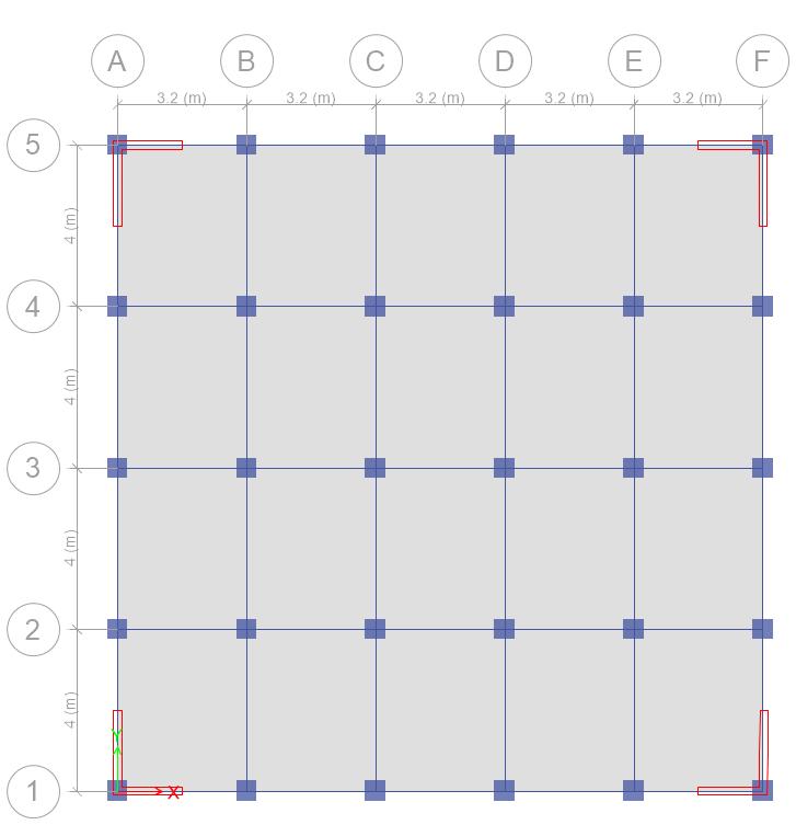


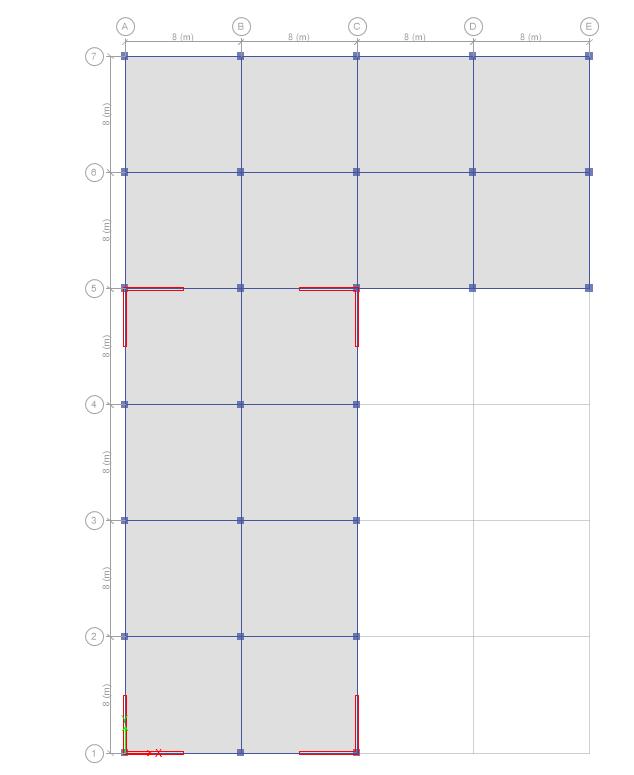

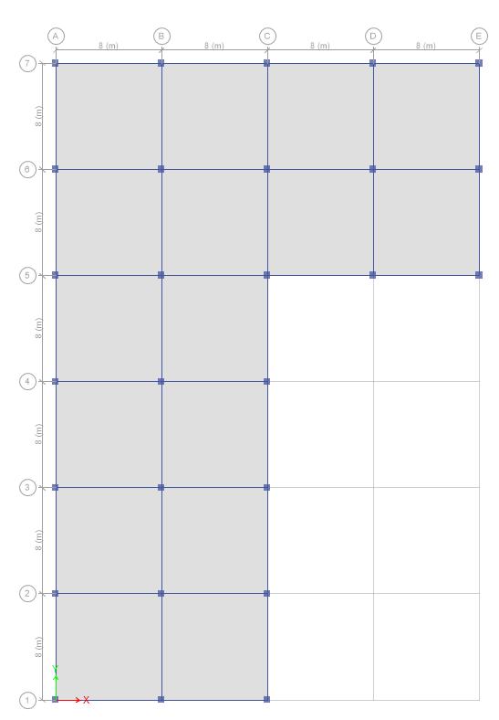
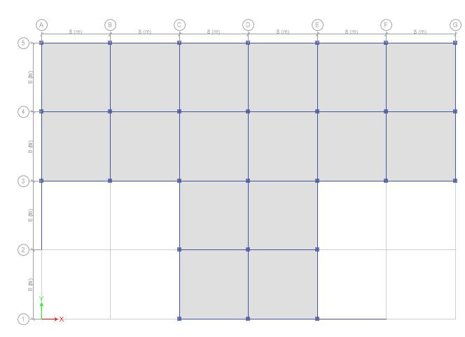
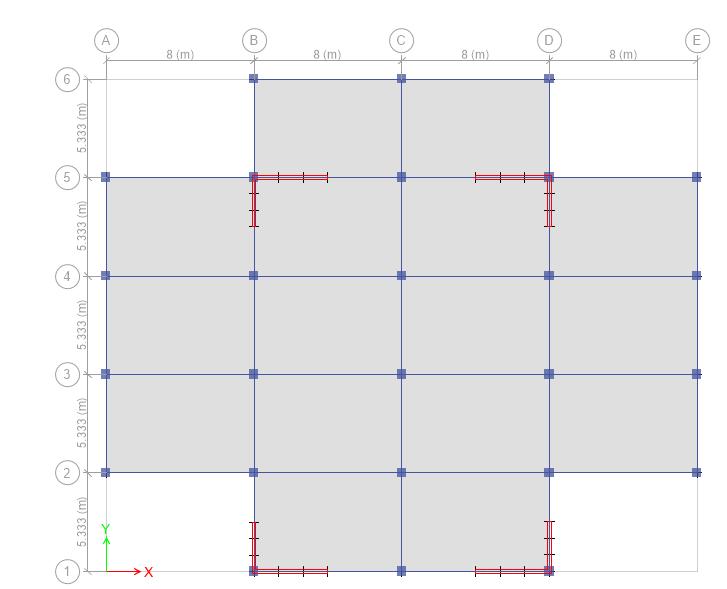
PLUSSHAPEDWITHOUTSHEARWALL
ACTUALSTEPBYSTEPPROCESSFORETABSSOFTWARE.
2.6 MODELLING OF STRUCTURE
MODELLING: modelling is consists of various types of materialsandloadpatternsasfollowbelowas:

1. Definingmaterials.
2. Definingsections.
3. Definingdiaphragm.
4. Definingloadpattern.
5. Definingmasssource.
2.7 DRAWING
1. Assigningsupport.
2. Assigningload.
3. Assigningdiaphragm.
4. Assigningmesh.

5. Definingloadcombination.
2.8 ANALYSIS OF STRUCTURE :
ANALYSIS : The analysis of structure consists of shear force and bending moments of entire structure.
1. Bendingmomentdiagram.
2. Shearforcediagram.
3. Axialforcediagram.
4. Reactions.
5. Responsespectrum.
6. Storeydrift.
7. Storeydisplacement.
8. Timeperiod.
9. Modalparticipatingmassratio
3.Designingofbuilding:
Designing: The designing is importantpartofstructure.
Designing is mainly used to calculation of area of reinforcement of structure and number bars calculating of structure. STEPBYSTEP
Step-1: Open ETABS Software
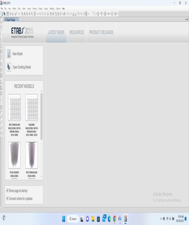
Select all appropriate data and click OK
Again one dialogue box will open
click > Ok
click > custom story data > Edit story data
Click >custom grid spacing > Edit grid data
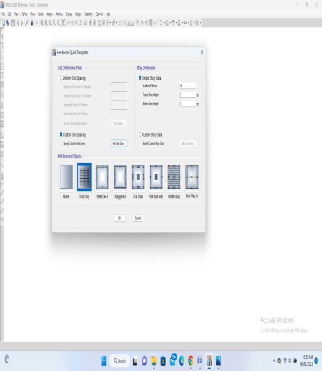
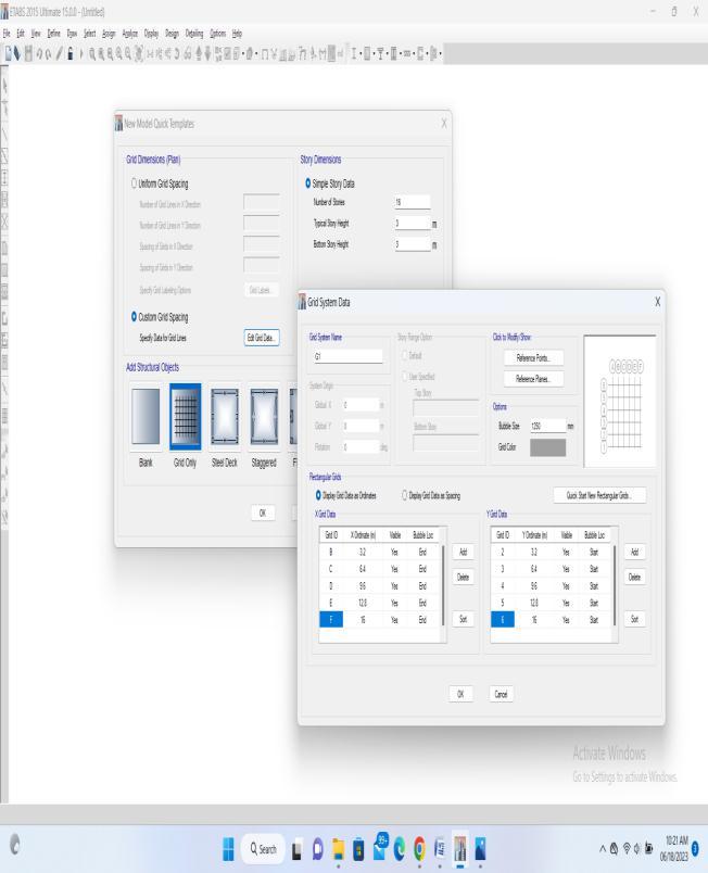
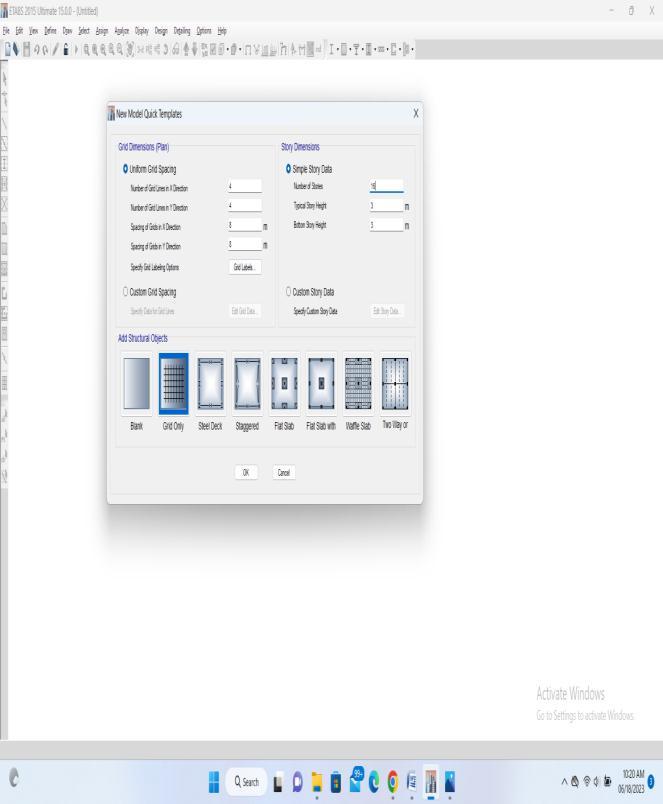
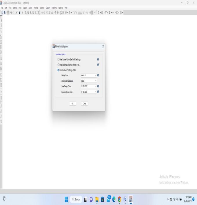
set the x and y ordinates as below
click > OK
STEP-2
Go to Define tab
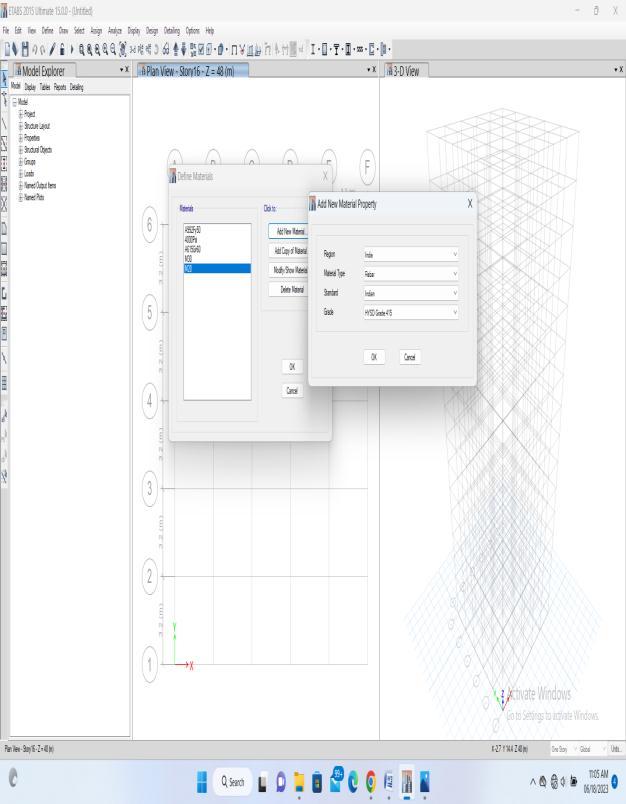
Click > define materials

one dialogue box will open
Define material of M30 grade


Again one more dialogue box will open
Define material of M20 grade

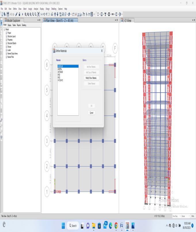

Define rebar’s materials
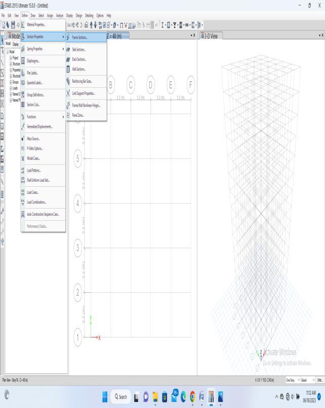

One dialogue box will open
Click ok Step -3
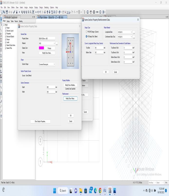
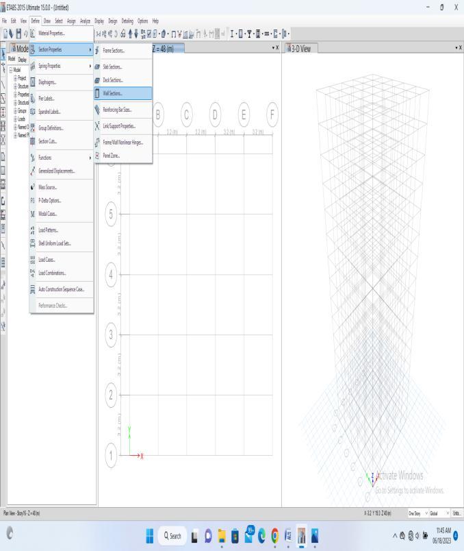
click on > define, then click >>> section properties
again click >>> frame sections


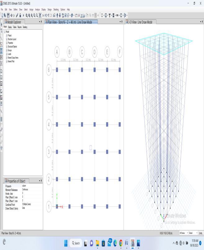
Click add new property
Column (500mm X 500mm)
Beam (300mm X 600mm)
Column details
Beam details
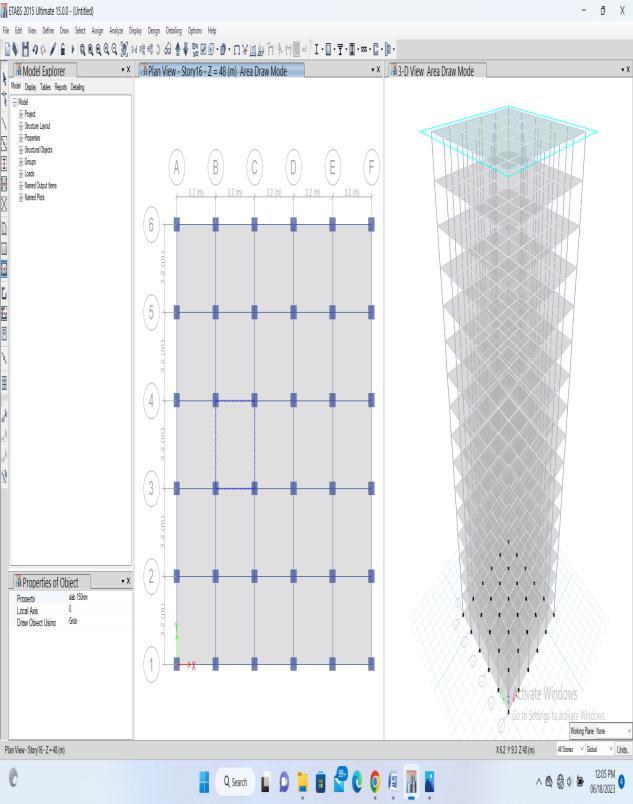
click on > define, then click >>> section properties

again click >>> slab section
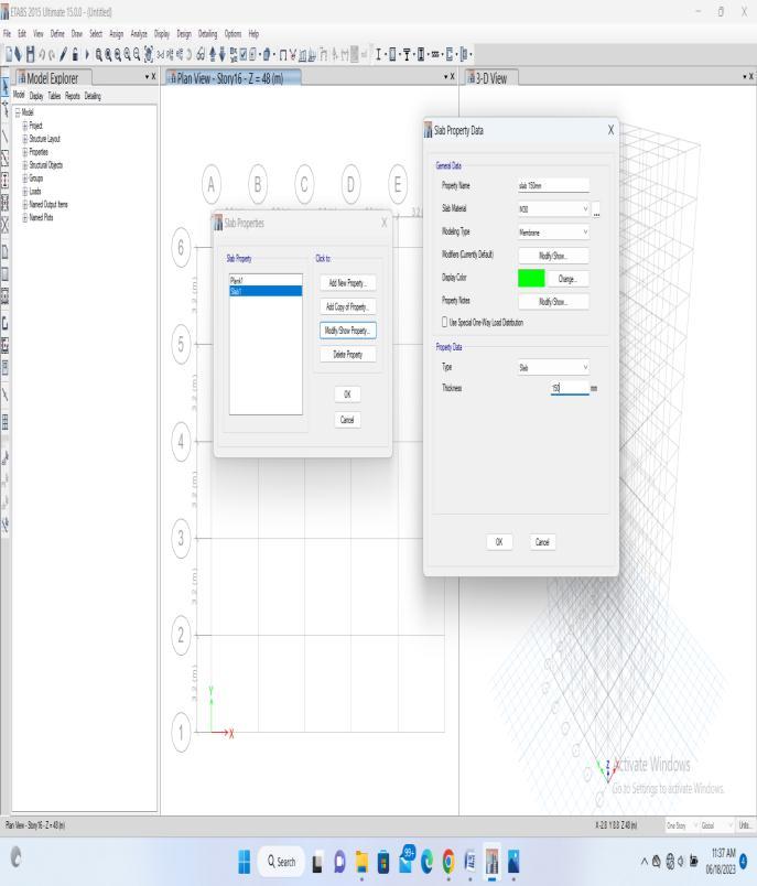
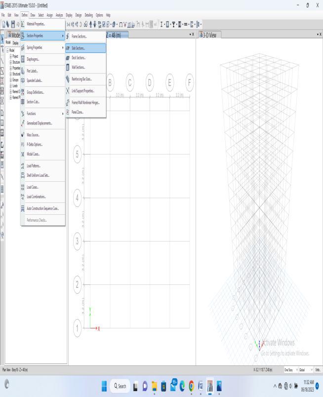
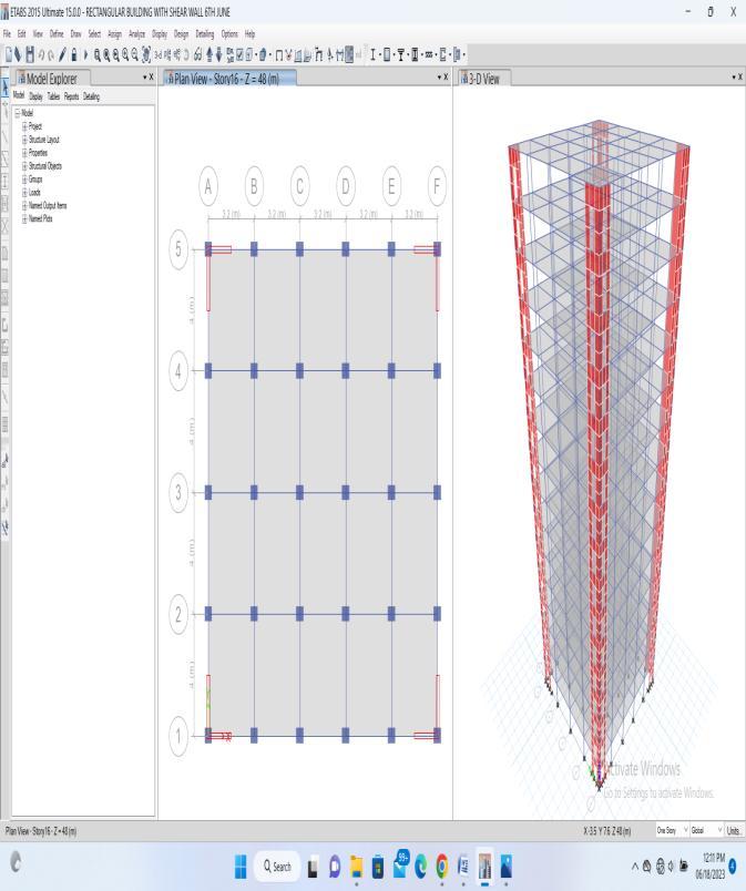
click >>> add new property slab is 150mm thickness for m30 click >>>ok Define shear wall






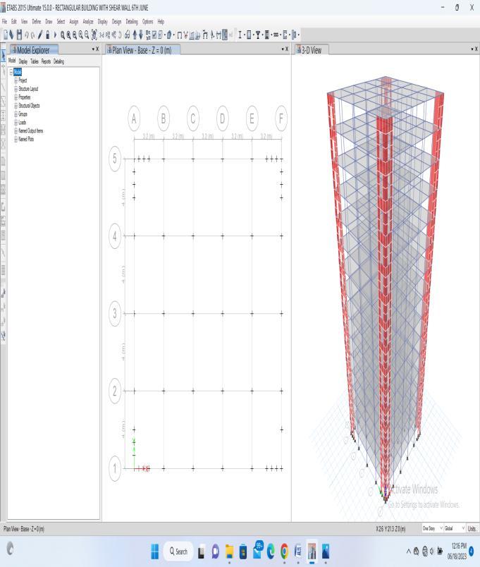
Define load combination
Run analysis(f5)
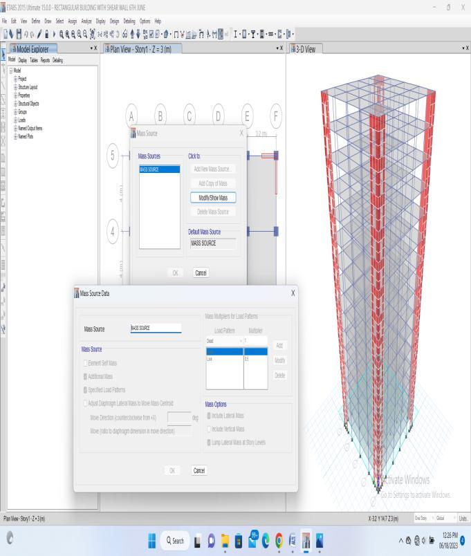
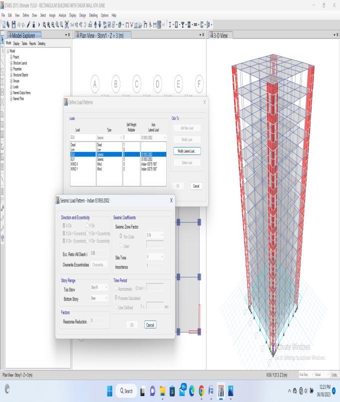
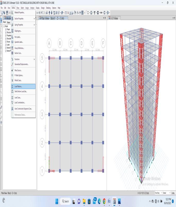
Model check
Results
3 RESULTS & CONCLUSION.

5. AUTOLATERAL LOAD SEISMIC STOREY TO STOREY EQX IN X DIRECTION (WITH SHEAR WALL)


4. LITERATURE REVIEW

1. IS456:2000[22],Thisstandardistypicallyapplied to both basic and reinforced building forms. The focushereisontailoringthestructure’slayoutto theneedsoftheclient.Cementconcreteworkisto beexecutedundertheleadershipofaqualifiedand experiencedsupervisor,andthedesignoftheplan and reinforced cement concrete work is to be entrustedtoaqualifiedengineer.
2. Bruce R.Ellingwood (2001) [7]earthquake resistance and design process based on the more reasonable probability-based treatment of uncertaintyareresearchedfortheirpotentialand futureimprovement.
3. IS 1893(part1):2002 [21] Buildings, elevated structures, industrial and stack-like structures, bridges, concrete masonry and earth dams, embankments and retaining walls, and other structures are all covered by the standard’s basic provisions,whichaddressseismicloadassessment andearthquakeresistantdesign.
4. S.K. Ahirwar, S.K.Jain and M.M.Pande(2008): Possibleeffectsofanearthquakeonmulti-storyR.C. Construction of framed structures in accordance withIS:1893-1984andIS:1893-2002.Theylooked at structures of 3, 5, 7, and 9 stories and studied them separately. Five distinct sequences were determinedforeachstructure.Analysistechniques such the Seismic Coefficient, Response Spectrum, and Modal Analysis were used. Earthquake reactions, such as ground shaking and building shaking.
5. Geotechnical EarthquakeEngineering(StevenL. Kramer), (2013) Introduces earthquake engineering,geotechnicalengineering,seismology, and structural engineering. The author discusses earthquake damage types, ground motion measurements, earthquake hazards, and earthquakeresponsetechniques.
6. Anil K. Chopra (2015) [17]This book covers earthquake analysis, structural response, and buildingdesignfromtheperspectiveofstructural dynamics. This text is dedicated to the dynamic analysisanddesignofmulti-storybuildingsinthe faceofearthquakes.
7. Inchara K P, Ashwini G (2016):This research aimed to examine the behavior of R.C framed irregular buildings under gravity loads and in varyingseismiczones,aswellastodeterminethe effectofvaryingpercentagesofsteelandvolumesof


concrete.Andtolearnhowtheproportionofsteel reinforcement and the amount of concrete differ depending on whether the structure was constructed according to IS 456:2000 for gravity loads or IS 1893(Part 1): 2002.for earthquake tremors in various regions. Five (G+4) different models were investigated in this analysis. The effectsofgravityandearthquakeforcesinavariety of seismic zones were simulated and investigated forallfourmodels.Themodelswereanalyzedwith ETABS program. Their findings suggest that the volume of concrete and the weight of steel reinforcementneededforfootingsincreasedfrom zoneIItozoneV,andthatthesametrendheldtrue for beams, with the percentage of steel reinforcement increasing as the zone number increasedfromIItoV.
8. Aniket A. Kale et al. (2017) [4]performedwind andseismicstudyonfourdistinctbuildingdesigns inthesamelocation(15,30,and45stories)using state-of-the-artsoftware(CSIETABS).Themethod of response spectra was utilized to identify the dynamic effects. Story displacement, story drift, baseshear,overturningmomentsMz,acceleration, andtimeperiodhaveallbeentakenintoaccountin thecomparison.Ithasbeendeterminedthata15storybuildingisthesafestdesignforwithstanding strongwindsanda15-storytriangularbuildingis the safest design for withstanding strong earthquakes.Maximumearthquakeandwindeffect areminimizedina45-storycircularorrectangular building. Both wind and seismic effects must be carefullyconsidered for buildings over15 and 30 storiesinheight,respectively.Anearthquakeisless ofaconcernthanwind.
9. Albert Philip et al. (2017) [5I] Analyzed the seismic properties of a G+12 reinforced concrete building with both a regular and irregular floor layoutinearthquakezoneIIIinIndiausingtheCSI ETABSprogram.Theanalysiswasconductedusing a technique called response spectrum analysis. Parameters including torso displacements, torso drifts,torsoshear,andtorsostiffnesswereusedto makethecomparison.Alinearrelationshipbetween story displacement and building height has been established.Foranirregularbuilding,themaximum storeydrifthappenedonthesecondlevel,whilefor aregularbuilding,itoccurredonthefourthstory. The greatest shear between stories was recorded between the first and second floors of a regular building, and on the first level of an irregular building.Bothbuildingshavenon-linearchangesin stiffnessacrosstheirstoreys.

10. G. Guru rasad et al. (2017) [1]Using ETABS, we ran a dynamic analysis of a six-story, reinforced concrete (RC) building with a C and rectangular layout.Parametersincludingsway,shear,support reactions, style of construction, and section cut forcehavebeencompared.
11. Conclusion:It was determined that the L-shaped planhadthehighestvalueofstoryshearcompared to the square and circular plans. In all three scenarios, values in the stories drift from left to right in the X direction, while rising in the Y directionfromtoptobottom.Itwasdiscoveredthat irregular plan structures may withstand higher foundation shear when earthquake loads are applied in the Y direction than rectangular plan structures. Results were better for regular and LshapedbuildingsthanforC-shapedstructures.
12. AthulyaUllas et al. (2017) [2]:conducted wind studies on structures with complex geometries, includingtheY,Plus,andV.Modelingandanalysis ofbuildingswiththeY,Plus,andVfloorplansare performedinETABS2016.Thestoryforceisfound tobeconstantacrossallbuildingtypes,indicating thatitisindependentofbuildingform.AV-shaped structure is shown to have the most lateral displacement. The Y-shaped building is the most structurally unstable of the selected shapes, with themoststoreydriftcomparedtotheothershapes. Ontheotherhand,thePlus-shapedbuildingisthe moststable,withtheleastlateraldisplacementand theleaststoreydrift.
13. Pradeep Pujar et al. (2017) [3]investigated the seismic effectivenessofirregularbuildingswitha heightofuptoninestories(G+9)withandwithout shear walls. The I, L, and C shapes of floor plans were taken into account. During the research, researchersinvestigatedbothbareframeandshear wallmodels.Themodelshavebeenexaminedwith the help of E-tabs V 15.0.0 software and the Equivalentstaticmethod.Parameterslikevertical movement,verticaldrift,andhorizontalshearhave been used to draw comparisons. Great results in baseshear,storydrift,anddisplacementhavebeen observedinL-andC-shapedstructureswithShear walls.WhilethebaseshearintheXandYdirections isgreatestfortheI-shapedbuildingwiththeshear wall, it is only slightly greater for the L-shaped building.Whencomparedtoabareframebuilding, a structure with a shear wall is more effective at withstandingseismicwaves.
5. CONCLUSION:
MaximumstoreydisplacementishighervalueofL shaped structural building and lower value of structure is rectangular shape of structure in x directionofdisplacement.Andstoreydisplacement inydirectionofhighervalueisLshaped Andsquareshapeofbuildingislowervalueofdisplacement.
Irregular types of buildings are maximum displacementthanregulartypeofbuildings.
Maximum storey drift is higher value in irregular typeofbuildingsandlowervalueinregulartypeof building.
Irregulartypeofbuildingstoreystiffnessishigher thanregulartypeofbuilding.
zDisplacement diaphragm is higher value of plus shapedirregulartypeofbuildingandlowervalueof squareshapedregulartypeofbuildingwithshear wall.
DisplacementdiaphragmishighervalueofTshaped irregulartypeofbuildingandlowervalueofsquare shapedregulartypeofbuildingwithoutshearwall.
Drifts diaphragm is maximum for irregular type building and minimum value of regular type of buildingswithorwithoutshearwall.
Rectangular&squareshapedbuildingsaresaferfor earthquakes as compared irregular buildings are moreunsafestructures.
irregular type of buildings are having some problemswindloadsandseismicloads
Overcometheproblemsoflateralforcesbyadding oftheshearwall.
Regular type of buildings are having less displacement & drifts and irregular type of buildingsarehavingmoredisplacement&driftsas comparedtoregularbuildings.
6. REFERENCES:
1. Geeta Mehta, Bidhan Sharma and anuj Kumar (2016)optimizationofMembersizeandMaterials for Multi storied RCC buildings using ETABS in India. International journal of science and technology.
2. Hatimsaleem,LPshrivastava(2019)comparative study of different types of shapes of building and design for wind loads by using ETABS in India. Publishedby(IRJET).

3. Pushkar rathod , rahul chandrashekar (2017) earthquakeanalyzingofhighraisedstructuresfor varioustypeofshapesbyusingETABS(IRJET).
4. M Pavani, G Nagesh Kumar, Dr. Sandeep pingale (2015) design and analysis of multi storied buildings with shear wall by using ETABS. International journal of scientific & engineering research (ISSN).
5. Plain and reinforced concrete code of practice fourthrevision(IS456-2000)BUREAUOFINDIAN STANDARDS manakbhavan,9bahadurshahzafar margiNEWDELHI.
6. INDIANSTANDARDCRITERIAFOREARTHQUAKE RESISTANTDESIGNOFSTRUCTURESfifthrevision (IS1893part1–2002)
7. Indianstandard(IS1987:part-1to3)
BIOGRAPHIES
HARISHBABU.ALURI
M.TECH STRUCTURAL ENGINEERING

