Design, Simulation & Optimization of Gravity Spiral Roller Conveyer with Auto Collision Avoidance System

1,2,3,4BE Mechanical Students, Mechanical Engineering Department, Pune Vidyarthi Griha’s College of Engineering and Technology and G.K. Pate (Wani) Institute of Management, Pune – 411009 5Project Guide & Assistant Prof. Mechanical Engineering Department, PVG’s COET & GKPIOM, Pune – 411009 ***
Abstract - The aim of this paper is to design, simulate, analyze and optimize the vertical gravity spiral roller conveyor for defined problem statement of 5 storey building. This paper also aims to design an advanced auto collision avoidance system to avoid collision of wooden boxes coming from previous floor and the entry from current floor using mechatronics system. Solid modelling was done using CAD software and linear, modal analysis using finite element analysis software. Design is optimized for weight reduction, costeffectivenesswithoutaffectingitsstrengthanddurability. This paper also includes mathematical calculations, conceptualanddetaileddesignwithanalysisforvariousparts of conveyor system which are designed.
Key Words: Material Handling, Spiral Conveyor, Optimized Design, Reduced Weight, Collision Avoidance
1.INTRODUCTION
Conveyors aremachinesusedforcontinuouslyor intermittentlymovingbulkorunitloadsfromonepointto another along a fixed path. The primary function of a conveyor is to transport materials. Roller conveyors, specifically, consist of a series of rollers mounted on bearings between two side frames that are supported by standsortrestlesplacedonthefloor.Therollersarespaced inamannerthatensuresthattheunitloadissupportedbyat leastthreerollersatalltimes.
Rollerconveyorsarecategorizedintotwogroups: unpoweredandpowered.Unpoweredrollerconveyorsrely onmanualforceoramovingchainorropeorgravitational forcetomovetheloads,whilepoweredrollerconveyorsare drivenbyoneormoremotors.Thepoweredconveyorscan beinstalledataslightinclineandcanmovetheloadineither direction by changing the direction of the roller rotation. Rollerconveyorsaresuitableforconveyingunitloadswitha rigid,flatsurfaceandarewidelyusedinvariousindustries such as manufacturing, assembly, packaging, and warehousing.However,theyarelimitedinthattheycanonly beusedforobjectswithrigidflatsurfacesandforrelatively short distances. Additionally, gravity roller conveyors requiresideguardstopreventtheloadfromfallingoffand havetheriskofacceleratingloads.
2. PROBLEM DEFINITION
To design a vertical gravity spiral conveyor for transfer of boxesofmaximumsizes2ft×2ft×1.5ftweighing60kgeach andfor5storybuildingfrom5th,4th,3rd,2nd,1sttoground floortodispatch.
Table -1: Componentsofdesignedconveyorsystem:
3. OBJECTIVES
1. Tostudytheexistingconveyorsystems
2. To design the optimized solution for defined problem statement
3. Toreducetheweightandcostofoverallsystem.
4. To implement the automatic system for collision avoidanceofboxes.
4. SCOPE OF WORK
1. Design of Helix angle based on principle of conservation of energy for vertical gravity spiral conveyor.
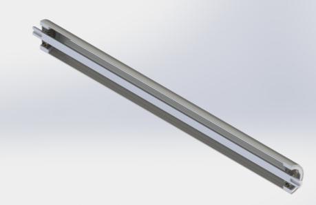
2. Design of roller (shaft, pipe, bearing and sealing arrangement)
3. Identificationofnumberrollersincontactwitheach boxbasedonminimumandmaximumboxsizes.
4. Design of spiral conveyor with box entry at every floor.
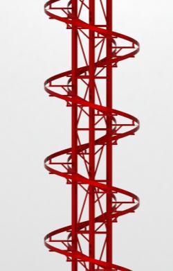
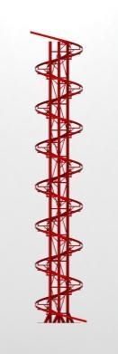
5. Solidmodelofverticalgravityspiralconveyor(using CADsoftware).
6. Simulation,static structural and modal analysis of spiralconveyorusinganalysissoftware.
7. PreparationofDetailedmanufacturingdrawingsand BillofMaterial(BOM)forSpiralConveyor.
5. STUDY OF EXISTING CONVEYOR SYSTEMS
Conveyorsystemsarematerialhandlingsystemsthatare designedtotransportmaterials,products,andpackagesfrom oneplacetoanother.Theyplaya crucial roleinindustries suchasmanufacturing,distribution,andwarehousing,and areoftenusedtotransportheavy,bulky,orawkwarditems thatwouldbedifficulttomovebyhand.
There are several types of conveyor systems, each designedtomeetspecificneedsandrequirements.Hereare someofthemostcommontypesofconveyorsystems:
Belt Conveyors: These are the most commonly used conveyors and are ideal for transporting products that requirecontinuoushandling.Theyuseacontinuousbeltto moveitemsalongahorizontalorinclinepath.
Roller Conveyors: Theseareusedforheavy-dutyloads andareparticularlyusefulfortransportingproductsthatare awkward to handle, such as large boxes or crates. They consistofaseriesofrollersthatrotatetomoveitemsalonga horizontalpath.
Chain Conveyors: Thesearesimilartorollerconveyors andareusedforheavy-dutyloads.Theyusechainstomove itemsalongahorizontalorinclinepath.
FlexibleConveyors:Thesearedesignedtohandlelightto mediumloadsandareidealfortransportingitemsintight spacesoraroundcorners.Theyconsistofaflexiblebeltthat canbendandturntofollowthedesiredpath.
Spiral Conveyors: These are used for vertical transportationandareidealformovingproductsupordown between levels. They consist of a spiral conveyor belt that rotatestotransportitemsvertically.
Pneumatic Conveyors: Theseareusedfortransporting lightweight products and use air pressure to move items alongahorizontalorinclinepath.Theyareidealforhandling delicateorfragileitems.
Overhead Conveyors: These are used for moving products along an overhead path and are ideal for transportingitemsinafactoryorwarehouse.Theyconsistof aseriesoftrolleysthatmovealonganoverheadtrack.
Conveyorsystemsplayavitalroleintheefficienthandlingof materials,products,andpackagesinvariousindustries.By selecting the right type of conveyor system for a specific application, businesses can improve productivity, reduce costs,andensurethesafeandefficienttransportationoftheir goods.
6. DESIGN OF PARTS IN CONVEYOR SYSTEM
Partsdesigned:
1. RollerAssembly
2. Frame
3. Column
6.1 DESIGN OF ROLLER ASSEMBLY:
Rollerpitchinagravityrollerconveyordesignrefers tothespacingbetweentherollersthatsupporttheload.The maximumpitchshouldnotbemorethanhalfthelengthofthe loadbeingcarriedandevenlessforgoodsthataresensitive tojerksorshaking.
The design calculations in this conveyor focus on determining the force needed to move the load and the incline angle required for the conveyor to work. The resistancetomotionoftheloadismadeupof:
1. Frictionbetweentheloadandrollers
2. Frictionintherollerbearings
3. Theresistancefromtheloadslidingontherollersand theforcerequiredtogettherollersmoving. Table
=Numberofrollerssupportingload
=Journalradius
=Partofweightofeachloadcarriedbyeachroller
=Kineticcoefficientoffriction
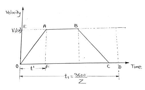
Frictionslidingforceduringtime is=
Ifthereare numberofloadsmovingsimultaneouslyon theconveyor,thenaveragetotalresistancedurtosliding& accelerationwillbe,
Workdonebytheload=
Where, =Distancemovedbyload
=time ; =Linearvelocityofload
Distancetravelledbyanypointontheperipheryoftheroller
willbe (areaOAF),
Whichisalsoslidingpath.Thisshowsthathalfofthework donebyloadisspentinovercomingthefrictionandother halfisusedinimpartingkineticenergytotheroller.
If isweightofroller,then
factorofvaluebetween0.8to0.9becausenotall themassoftherollermovingpartsisonthe peripherynotmovingwithvelocityV


Therefore, work done due to sliding & acceleration of one rollerisgivenby,
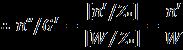
Totalresistancetomotionoftheloads,whichistheforce requiredtomovetheloadsonaunpoweredconveyoris,
Thereare‘n’numberofrollersinatotallength‘L’,Total workdonein‘n’numberofrollersformovingoneload throughoutthelengthofconveyor.
Wecandefineequivalentresistancetomotionfactor by anequation,
Averageresistancetomotionononeloadduetosliding& acceleration,
let,D=Rollerdiameter=2R
d=Journaldiameter=2r
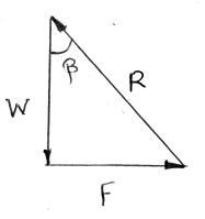
Forcalculatingtheminimuminclinationangle‘β’ofagravity conveyor,whichwillallowmovementofaloadduetogravity only,resistancetoonlyoneloadneedtobeconsidered,which shouldbeovercomebythecomponentofgravitationalforce ontheloadalonginclinationoftheconveyor.

=numberofrollerssupportingeachload
Weightofeachload= =
Roller Calculations:
Pitch=200mm[Atanytime,aminimumof3rollerswill beincontactwithload]
Totallengthofconveyor=2meters=2000mm
Noofrollernecessary=2000/200=10
Relationship between lifeinmillion revolutions and life in workinghoursisgivenby:
Bearing Selection:
Forsimplicity,deepgrooveballbearingisused.
Relationship between dynamic load carrying capacity, equivalentdynamicload&bearinglife:
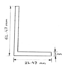
6.2 DESIGN OF FRAME:
ForMildsteel: ;
ConstantUDL&FOS=2
60Kgweightisactingontherollersthentotal200kgis actingfor10rollersatatime+additional(2.5×10)
LChannel: ; ;
ConsideringSSBwithUDL,
MaxDefection,
8. ANALYSIS AND OPTIMIZATION:
WehaveusedAnsyssoftwareforComputerAided Analysisofdesignedcomponents.
8.1 STATIC STRUCTURAL ANALYSIS:

As compared to length 2060mm deflection of 0.123mm is very negligible hence selected channel is safe.
7. CAD MODELLING USING SOLIDWORKS
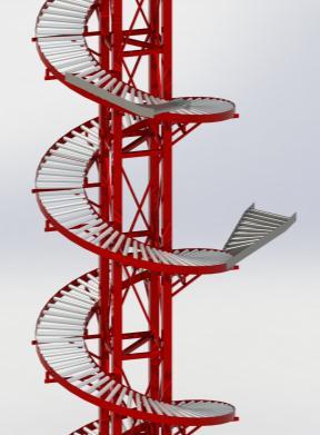
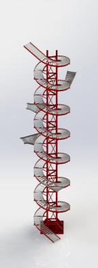
SOFTWARE:
A static analysis is a method that calculates the impactofconstantloadsonastructure,whileignoringthe effectsofinertiaanddampingcausedbyvaryingloadsover time.However,staticanalysiscanstillconsidersteadyinertia loadssuchasgravityandrotationalforces.Thismethodcan be used to design and analyze roller conveyors for weight optimization and material savings based on their velocity. Additionally, time-varying loads can be approximated as static equivalent loads, such as wind and seismic loads commonly defined in building codes. To perform a static analysis,elementsareselected,andmaterialpropertiesare applied to determine the displacement, stress, strain, and forcesinstructuresorcomponentscausedbyloadsthatdo not induce significant inertia and damping effects. The analysisassumesthattheloadsandthestructure'sresponse changeslowlyovertime,andtheconditionsremainconstant.
Critical load condition:
Loadactonanythreerollershencebyconsidering120kg loadactonthreerollersmaximumdeflection,maximum stressvaluesarecheckedforexistingdesign.
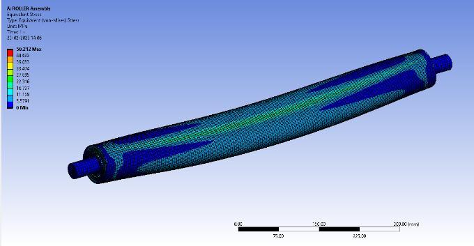
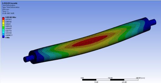
Static Structural Analysis of roller:
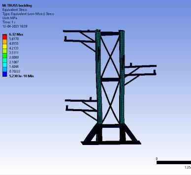
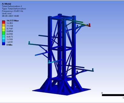
Modal Analysis of Designed Truss frame:
Stress:50.212MPa
Strain:0.081mm
FOS:250/50.212=4.97
8.2 MODAL ANALYSIS:
Modalanalysisisatechniqueusedtoidentifythenatural frequenciesandmodeshapesofasystem.Ithelpstocreatea mathematical model that describes the system's dynamic behaviorbydeterminingitsinherentdynamiccharacteristics like natural frequencies and damping factors. When the loadingisintheverticaldirectionduetogravity,itisessential toidentifythemodeshapesthatdemonstratemovementin the same direction. Modal analysis helps engineers to understandthedynamiccharacteristicsofastructure,howit responds to different types of dynamic loading, and avoid resonantvibrationsthatcancausedamage.Itisanessential tool for engineers to optimize the design and ensure the safetyofthestructure.
Deformation:14.572mm
Frequency:23.431Hz
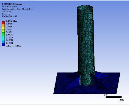
8.3 COMPARISON BETWEEN COLUMN AND TRUSS FOR DESIGN OF FRAME:
Stress:2.104MPa
Strain:0.009mm
FOS:250/2.104=118.5
Stress:6.32MPa
Strain:0.032mm
FOS:250/6.32=39.55
Design Max. Def (mm) Natural Freq. (Hz)
Column 25.008 mm 25.983 Hz
Truss 24.379 mm 25.822 Hz
ThemaximumdeflectionofTrussisat25.822Hzwhichis lessthanthenaturalfrequencyofcolumn.
Asfactorofsafetyofrollersubassemblyandrollersisvery highthereisscopeofweightreductioninthiscomponent. Also factor of safety of other components like frame and supportsisalsogreaterthan1.5sowecanreducetheweight.
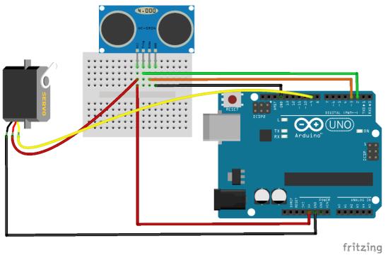
9.
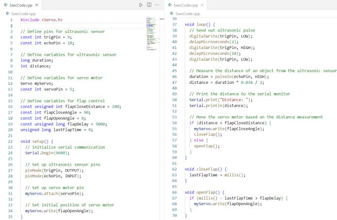
Inthiscode,the closeFlap()functioniscalledwhenevera boxisdetectedwithintherangeof100cmoftheultrasonic sensor.Thisfunctionsetsthepositionoftheservomotorto flapCloseAngle,whichshouldclosetheflapattachedtothe servo motor. Additionally, the lastFlapTime variable is updatedtothecurrenttimeusingthemillis()function,which willbeusedtodeterminewhentoopentheflapagain.
The openFlap() function is called when a box is not detectedwithinrangeoftheultrasonicsensor.Thisfunction checksifatleast5secondshavepassedsincethelasttimethe flap was closed using the lastFlapTime variable and the millis() function. If at least 5 seconds have passed, the positionoftheservomotorissetto flapOpenAngle,which shouldopentheflapattachedtotheservomotor.
Note that we may need to adjust the values used for distance measurements and flap control based on specific needs and hardware setup. Additionally, we may need to adjustthe myServo.attach(servoPin) linetousethecorrect pinforourservomotor.
10. CONCLUSIONS
1. Designedoptimizedverticalgravityspiralconveyor for transfer of boxes ofmaximum sizes 2ft× 2ft×
1.5ftweighing60kgeachandfor5storybuilding from 5th, 4th, 3rd, 2nd, 1st to ground floor to dispatch.
2. Reduced weight by 20% using truss column over roundcolumn.
3. Implemented Auto Collision Avoidance system to avoidcollisionbetweenboxes.
11. ACKNOWLEDGEMENT
We are acknowledging Mr. Mahendra Khollam (MD, Mahendra Technologies, Pune), Prof. Dr. H.G.Phakatkar (Phakatkar Engineering Academy), Prof. Ami Barot (ProjectGuide,MechanicalDepartment,PVG’sCOET,Pune), Prof. Dr. M. M. Bhoomkar (HODMechanicalDepartment, PVG’sCOET,Pune) forkindguidanceandsupport.
12. REFERENCES
[1] https://www.ijert.org/research/optimizationtechnique-used-for-the-roller-conveyor-system-forweight-reduction-IJERTV1IS5216.pdf
[2] https://www.researchgate.net/publication/317032679
[3] Dr. Siddhartha Ray, “Introduction to Materials Handling”,NewAgeInternationalPublishers,2013ed.
[4] “DesignofMachineElements”byVBBhandari,McGraw HillEducation,Thirdedition.
[5] “MachineDesignDataBook”byVBBhandari,McGraw HillEducation,2014edition.
13. BIOGRAPHIES
Mr.PratikAnilChougule BEMechanicalstudentat PVG’sCOET,Pune.
Mr.ManoharMilindPitre BEMechanicalstudentat PVG’sCOET,Pune.
Mr.GauravKaduBhamare BEMechanicalstudentat PVG’sCOET,Pune.