Structural Analysis of Go-kart Chassis using different materials to find the suitable material for the given model
Atharva Kondhare, Sandesh Pawar, Anisa DiwanAtharva Kondhare, Dept. of Mechanical Engineering, VIIT College, Maharashtra, India
Sandesh Pawar, Dept. of Mechanical Engineering, VIIT College, Maharashtra, India

Anisa Diwan, Dept. of Mechanical Engineering, VIIT College, Maharashtra, India
***
Abstract - In the present work, the chassis of the go-kart is designed and simulated for different impact positions such as front impact, side impact, & rear impact tests for four different materials. Initially, the chassis was designed using 3D CAD software and then simulations is carried out in ANSYS Workbench. The work shows the failure criteria based on vonmises stress for selected materials. The work aims to get the perfect materials for chassis that can withstand the range of force that the drivers experience while driving low-ground clearance go-karts. The reason to carry out a range of force analysis is that the kart should have maximum value for the factor of safety. The same range of a force is carried out on all the impact positions. For the current analysis, the strength of materials and structural rigidity are the main consideration.
Key Words: Chassis; Go-Kart; CAD Modelling; AISI: Simulation.
1. INTRODUCTION
The Chassis is the metallic frame or Rigid Structure onto whichallothercomponentsofabodyarefixed.Theworkof the chassis is to carry the load of the vehicle and its passengerandresistthetorqueandthrustloadsfromthe engine and gearbox, as well as those from stopping and accelerating, survivingthecentrifugal force whenturning. The chassis' construction is made up of thick tubing and tubeswithdifferentcrosssectionsthatsupportthedifferent vehicle parts and protect the driver [1]. This work’s discussionandresultarebasedonthedesignandstructural analysisofkartchassisunderdifferentloadingconditions. The go-kart has an extremely low ground clearance comparedtoothercarsandisspecificallymadeforracing. Theengine,wheels,steering,tires,axle,andchassisarethe typical components of a go-kart. Go-karts cannot be equipped with suspensions because of their low ground clearance.[2].
Now,computer-aidedengineeringtoolsareusedtodesign landvehicles[3].Computerdynamicsimulationtechniques arefrequentlyusedtoexaminehowthosevehiclesbehave undervariousinputsituations[4].Finiteelementanalysisis usedforthestructuralanalysisofdifferenttypesofvehicles. The FEA is used to calculate the generated stresses and strainsfromdifferentinputscenariosthathavebeenapplied asboundaryconditions.[5].Internalandexternalloadsare
actingonaBody.Theinternalloadisbroughtonbythemass of the vehicle and payloads, while the external loads are broughtonbythewheel-groundinterface,movingthrough thesuspensionmechanismanditselasticcomponents,and fromtheaerodynamicfieldsurroundingthecarbody[1].
2. Methodology
1. Material Selection
The concerns of the manufacturer regarding laws and regulations,aswellassomecustomerdemands,determine an automotive chassis. Most producers favor affordable, secure, lightweight, and reusable materials. The primary considerationsforchoosingamaterial,particularlyforthe body, involve a wide range of properties like resilience, productioneffectiveness,and
thermal, chemical, or mechanical resistance. Mainly two materialsareconsideredwhileconstructingchassis&they are steel and aluminum. Aluminum is corrosion-resistant, however,duetoitslowflexibilitymodulus,itisnotableto replace steel parts. As a result, such components must be redesigned to adopt the same mechanical strength. It is utilizedaswheels,brackets,brakeparts,suspensionparts, steeringparts,andinstrumentpanelsinchassisapplications. Steelisthematerialofchoiceforproducersbecauseithasall the necessary qualities. Steel is now stronger, lighter, and morerigidthanitwasinthepastthankstoadvancements made in the steel industry. Steel's inherent capacity to absorbtheimpactenergycreatedinacrashmakesitideal forbodystructures.So,forbettermaterialSelectioninGokart chassis, we take AISI Steel Standards. The selected materialsareAISI1018,AISI1026,AISI4130,andAISI1020.
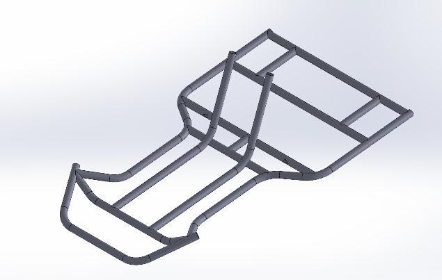
2. Modelling
The 3D model of the chassis is designed with the help of Solidworks.SolidWorksisasoftwaremainlyusedtodevelop mechatronicssystemsfrombeginningtoend.Usingthe3d sketchoptioninitiallychassissketchisformedinXY,YZ&XZ planes.Thenusingtheweldmentsmethodhollowpipesare created on the sketch. The hollow pipe is ISO 26.9 x 3.2 diameter. The chassis is formed by using hollow pipes as theyresultinlessweightascomparedtothesolidpipe
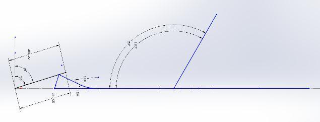
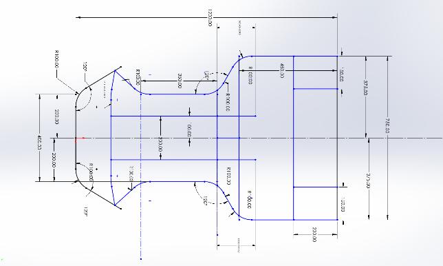
ForCADModelling
Scale:
Chassis Length= 2m
Chassis Width= 0.66m

Diameter Of pipe= ISO 26.9 * 3.2
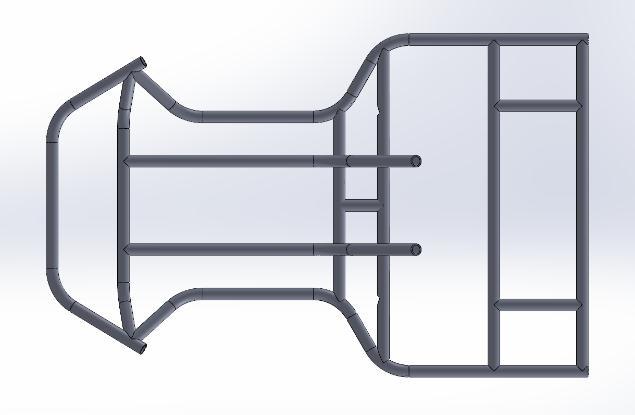
SolidWorksmakesitsimpletocreateapipestructureusing theweldmentmethodoroptionFeature.SolidWorksalso Offersa3dsketchingmethodThereforeitiseasytosketch thechassisinathree-dimensionalway
3. Fine Element Analysis (FEA)
The chassis behavior under actual physical force is understood using finite element analysis (FEA) [6]. To ensure safety when operating the go-kart, the chassis' structuremustbestrongandabletobeartheforcesapplied toit.Staticanalysisisnecessarytoensurethatthechassis complied with the specifications [1]. For Finite Element Analysis,AnsysSoftwareisused.
2.3.1.Meshing
Meshing helps to divide a complicated object into clearly definedcellswherethegeneralequationcanbeassignedso
thatthesolvercaneasilysimulatephysicalbehavior.Highly accurate simulations are made possible by the 3D CAD model'sincreasedaccuracyandprocessingtimeasthemesh becomesmoreprecise[6].
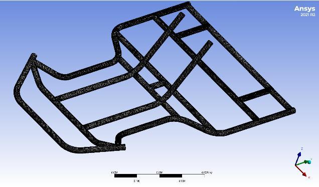
Thegeometryusedformeshistetrahedralandtheelement sizeiskeptto3mm.Totalnodesare2,20,000andelements are 8,04,100 physics preference is kept CFD, & Solver PreferenceisFluentAndElementOrderisLinear.

2.3.2.Boundary Conditions
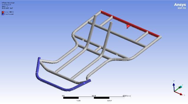
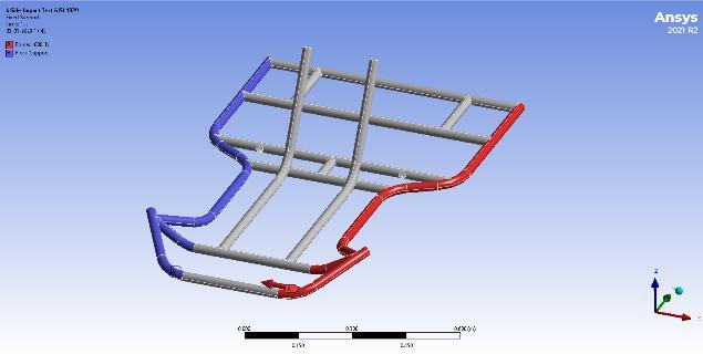
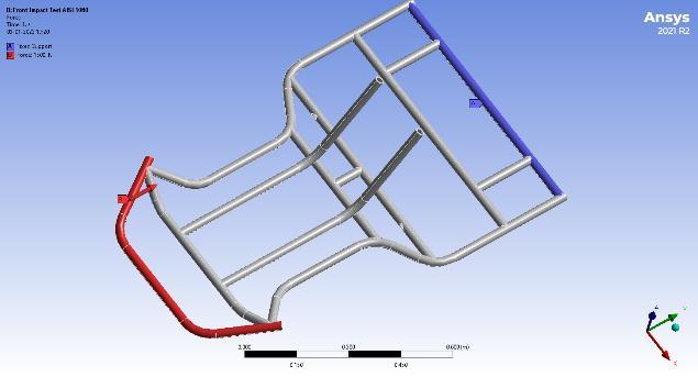
Threeconditionswereimposeddependingonthefront,side, and Rear impact tests. For the Front impact test, the rear section was fixed and a force was applied to the front section,asshowninFigure3.1.Forthesideimpacttest,One sideofthechassisisfixed,andontheotherside,theforce wasapplied,asshown in figure3.2. And fortheRearside impacttestthefrontsectionwasfixed,andforcewasapplied totherearsectionofthechassis,asshowninfigure3.3
2.3.3.Solution
Analysis of all selected materials was performed using ANSYStodeterminethefactorofsafetyanddeformationthat thebuiltchassisexperienceswhenaloadisappliedtoitin frontstaticimpactandSidestaticimpact[6].
FrontImpactTest
Letusconsiderforthefrontanalysistest,thatthemaximum weightofthedriveris100kg,andthemaximumweightof theGo-Kartisconsidered100kg;therefore,Assumingthe vehicleisstruckbytheappliedloadforabriefperiodata velocityof70km/hrduringthefrontsectionofthechassis, thegokart'sweightwiththeoperatorisassumedtobe200 kg.Analysisoftheimpactload'simpactvariesdependingon
the driver's perception of safety and is done for a range whereloadsaremeasuredat4g,6g,and8g.
SideImpactTest
LetusconsiderfortheSideAnalysistest,thatthemaximum weightofthedriveris 100kg,andthemaximumweightof thego-Kartisconsidered100kilograms;therefore,thetotal weightofthego-kartwiththeOperatoristakenas200kg. assumingthatthevehicleisbrieflyhitbytheappliedload while traveling at 70 km/hr in the selected section of the chassis.Analysisoftheimpactload'seffectvariesdepending onthedriver'sperceptionofsafetyandisdoneforarange whereloadsaremeasuredat4gand6g.
RearImpactTest
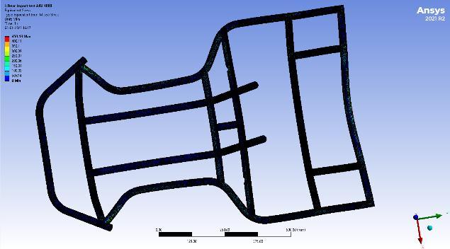

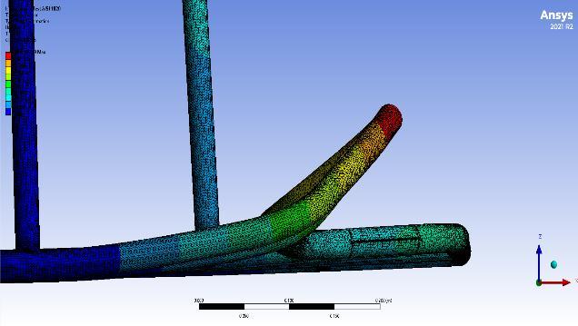


Letusconsiderfortherearanalysistest,thatthemaximum weight of the driver is 100 kilograms, and the greatest possibleweightoftheGo-Kartisconsidered100kilograms; therefore,thetotalweightofthego-kartwiththeoperatoris takenas200kg.assumingthattheloadstrikesthecaratthe velocityof70km/hrintheselectedsectionofthechassisfor a brief period. Analysis of the impact load's impact varies dependingonthedriver'sperceptionofsafetyandisdone forarangewhereloadsaremeasuredat4g,6g,and8g
For results, the calculations are done by using the F.O.S formula.Ifthefactorofsafetyisgreaterthanorequaltoone, thenthisdesignissaidtobesafe.Theloadsusedinimpact tests, the maximum deflection, and the induced Von Mise stressisdisplayedinthetables

4. CONCLUSIONS
1. Accordingtothefindingsofthisstudy,forfrontimpact tests,AISI4130materialperformswellunder4g,6g, and 8 g loads, with the highest factor of safety when comparedtotheselectedmaterial.
2. Inthesideimpacttest,allselectedmaterialsperformed wellunder4and6gloads,butAISI1080issaferthan othermaterials.
3. For the rear impact test, again, AISI 4130 is a safer material.
4. Fromtheoverallresult,AISI4130isthemosteffective material among the selected materials under 4 g, 6 g, and8gloads.
REFERENCES
[1] Jafri,Mohamad&Marwan,Shahrul&Lazim,Muhammad &Anuar,Nurul.(2019).FINITEELEMENTANALYSISOFGOKARTCHASSIS.e-AcademiaJournal.7.10.24191/e-aj.v7iSITeMIC18.5397.
[2] Raghunandan,D.,etal.“DESIGNANDANALYSISOFGOKART CHASSIS.” INTERNATIONAL JOURNAL OF ENGINEERING SCIENCES & RESEARCH TECHNOLOGY, Nov. 2016,https://doi.org/10.5281/zenodo.164912.
[3] Raphael, Benny & Smith, Ian. (2013). Engineering Informatics:FundamentalsofComputer-AidedEngineering.
[4] Mike Blundell, Damian Harty, Chapter 3 - Multibody Systems Simulation software, Editor(s): Mike Blundell, DamianHarty,TheMultibodySystemsApproachtoVehicle Dynamics(SecondEdition),Butterworth-Heinemann,2015, Pages 87-184,ISBN 9780080994253, https://doi.org/10.1016/B978-0-08-099425-3.00003-0.
[5] Saheb, H. S.; Kona, R. K.; Hameed, M. (2016). Design report of a go-kart vehicle, International Journal of EngineeringAppliedSciencesandTechnology,Vol.1,No.9, 95-102.


[6] Sanjeet Ramteke, and Vaishnavi Nambiar. “Material SelectionMethodologyforaGo-kartChassisUsingWeighted Decision Matrices.”Turkish Journal of Computer and MathematicsEducation,vol.13,No.2,2022,pp.539–50.
BIOGRAPHIES
SANDESHPAWAR
Dept.ofMechanicalEngineering,VIIT College,Maharashtra,India.
AtharvaKondhare
Dept.ofMechanicalEngineering,VIIT College,Maharashtra,India
ANISADIWAN
Dept.ofMechanicalEngineering, VIITCollege,Maharashtra,India.