
International Research Journal of Engineering and Technology (IRJET) e-ISSN: 2395-0056
Volume: 12 Issue: 03 | Mar 2025 www.irjet.net p-ISSN: 2395-0072
International Research Journal of Engineering and Technology (IRJET) e-ISSN: 2395-0056
Volume: 12 Issue: 03 | Mar 2025 www.irjet.net p-ISSN: 2395-0072
Savan C. Becker1 , Michael E. Johnson, PhD2, John Carrico Jr.3
1 Department of Engineering, Capitol Technology University, Laurel, MD, USA
2 Adjunct Professor, Department of Engineering, Capitol Technology University, Laurel, MD, USA
3 Chief Technology Officer/Astrogator, Space Exploration Engineering (SEE), Laurel, MD, USA ***
Abstract - Multiple National Aeronautics and Space Administration (NASA) sponsored and independent studies haveexaminedand/orproposeddeploymentofspacecraftin key cislunar orbits as part of LunaNet, a communications relay and navigation network to support operations on and around the Moon [1, 2, 3, 4, 5, 6, 7, 8, 9, 10]. Additional research promotes the possibility for immersive, collaborative, multi-user human and human-robotic exploration during future lunar and interplanetary space exploration initiatives, including Artemis [11, 12, 13, 14, 15, 16, 17, 18, 19, 20]. Delay (i.e., latency) due to distance and frequency/duration of access intervals are significant, fundamentalfactorsindeterminingtheextentandqualityof dynamic communications, teleoperation of robotic systems, andimmersiveinteraction – particularlyinspaceoperations [11,17,18,21,22,23,24]. Thisarticledescribeshowweused Systems ToolKit (STK) software to investigate the access intervals and path delays (PD) in an idealized lunar relay satellite constellation modeled on a proposed LunaNet baseline [3, 8, 9, 10, 25] We also compare these results to a hypothetical “Lagrange-Centric” (i.e., Earth-Moon L1) alternative relay constellation. While simplified, our estimatesforPDandaccessintervalsmayhelpbound“worstcase” scenarios and expectations when considering feasibility, quality, and frequency of collaborative cislunar explorationactivities.
Key Words: Technology, NASA, Space, Spaceflight, Artemis, Gateway, Shackleton, LunaNet, Satellite, Satellites, Communications, Constellations, Spacecraft, Moon, Mars, Cislunar, SpaceExploration, Telepresence, Exploration Telepresence, Astrodynamics, Orbits, Orbital Mechanics, Systems ToolKit, Satellite ToolKit, STK,Astrogator,CODE,Lagrange,Libration
Research conducted by independent investigators and sponsored by the National Aeronautics and Space Administration (NASA) suggests the possibility for immersive, collaborative, multi-user human and humanroboticexplorationoftheMoonduringtheplanned Artemis program [1, 11, 12, 13, 14, 15, 16, 17, 18, 19, 20]
Communications delays in space operations impact the extent to which astronauts, researchers, and enthusiasts can dynamically participate in collaborative exploration
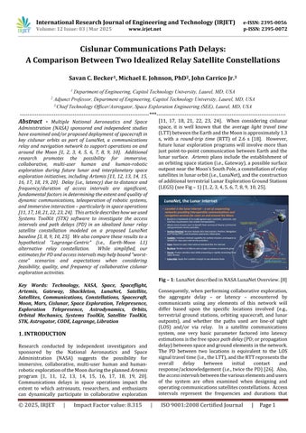
[11, 17, 18, 21, 22, 23, 24]. When considering cislunar space, it is well known that the average light travel time (LTT)betweentheEarthandtheMoonisapproximately1.3 s, with a round-trip time (RTT) of 2.6 s [18] However, future lunar exploration programs will involve more than justpoint-to-point communication betweenEarth and the lunar surface. Artemis plans include the establishment of anorbitingspacestation(i.e.,Gateway),apossiblesurface outpostneartheMoon’sSouthPole,aconstellationofrelay satellitesinlunarorbit(i.e.,LunaNet),andtheconstruction ofadditionalterrestrialLunarExplorationGroundStations (LEGS)(seeFig–1)[1,2,3,4,5,6,7,8,9,10,25].
Consequently,whenperformingcollaborativeexploration, the aggregate delay – or latency – encountered by communicants using any elements of this network will differ based upon the specific locations involved (e.g., terrestrial ground stations, orbiting spacecraft, and lunar outposts), and whether the paths used are line-of sight (LOS) and/or via relay In a satellite communications system, one very basic parameter factored into latency estimationsisthefreespace pathdelay (PD;orpropagation delay)betweenspaceandgroundelementsinthenetwork. The PD between two locations is equivalent to the LOS signaltraveltime(i.e.,theLTT),andtheRTTrepresentsthe overall delay between initial contact and response/acknowledgement(i.e.,twicethePD)[26]. Also, the accessintervals betweenthevariouselementsandusers of the system are often examined when designing and operatingcommunicationssatellitesconstellations. Access intervals represent the frequencies and durations that
International Research Journal of Engineering and Technology (IRJET) e-ISSN: 2395-0056
Volume: 12 Issue: 03 | Mar 2025 www.irjet.net p-ISSN: 2395-0072
various elements in a satellite-based communications network can connect with each other under ideal circumstances [26]. These time periods are usually dependent upon whether spacecraft and ground stations are“inview”ofoneanother,orifcontactcanbefacilitated byrelay–i.e.,viaelementsthatcanbridgethegapbetween theend-pointcommunicants.
In this article, we describe how we used System’s ToolKit (STK)orbitandtrajectorymodelingsoftwaredevelopedby AnsysGovernmentSolutions(AGI)toexaminebasicPDand access intervals between elements of two idealized satellite-based cislunar communications architectures [26]. The first is derived from NASA’s “minimal constellation”LunaNetconcept,asreviewedanddiscussed in several NASA and academic sources, including [3], [8], [9],and[10];wecallthis“LunaNetBaseline”. Thesecond imagines a “Lagrange-Centric” constellation, with three satellitesdeployedinphasedhalovariantorbitsaroundthe Earth-MoonL1librationpoint.
In the spirit of multi-user collaborative exploration, we focus on a conceptual scenario in which the goal is to achieve low-latency, concurrent communication between terrestrial researchers, personnel aboard a lunar orbiting facility,andexplorersontheMoon’ssurface[16,17,18,19, 20, 21, 22, 23, 24]. Note that all computations are generalized and based on idealized LOS parameters; they donotconsiderfactorssuchasterrainrestrictions,antenna pointing constraints, and other environmental or operationallimitations. Further,thisstudyfocusesonthe satellite elements comprising the possible LunaNet constellation, and – for simplicity – does not consider alternate communications methods that could help mitigate outages (i.e., deployment of antennas across the Moon’ssurface)[27]. Theprocesswassolelymeanttogain a baseline appreciation for “worst-case” space-associated PD/LTT values and access intervals; more detailed investigationislefttofutureresearch.
NASA has indicated that the “…incremental build-up of capabilities on and around the Moon is essential to
establishing long-term exploration of Earth’s nearest neighborandpreparingforhumanexplorationofMars”[1]. Several agency-sponsored and independent studies examined and/or proposed deployment of spacecraft in keycislunarorbitstosupportthedevelopmentofLunaNet, a lunar communications relay and navigation network, including: [2], [3], [4], [5], [7], [8], [9], and [10]. NASA is pursuing LunaNet with international partners, including the ESA via that agency’s “Moonlight” initiative [28, 29]. Thearchitecturewilllikelybeginmodestly–perhapswith a single relay satellite – but build up over time into a service-oriented,scalable,resilientnetworkofcommercial and government provided communications and PNT services[9]. NASA’sproposedGatewaylunarspacestation – in addition to being an operations and logistics hub for crewedmissionstotheMoonandbeyond–willalsoserve as a node in this evolving network, using its communicationsand rangingcapabilities to helpfacilitate cislunarhumanandroboticactivities[5,8].
For this paper, an idealized simulation of the cislunar environment as it may manifest during the early Artemis erawasconstructed,togainanappreciationforsomeofthe fundamental communications access and latency constraintsassociatedwithcislunarcommunications. This basic cislunar communications relay model was primarily informed by concepts laid out in several LunaNet design papersandoverviewpresentations,including: [3],[4],[8], [10], [30], [31], and [32]. Significant components of this overallarchitectureinclude:
▪ The Gatewaystationina southernL2 nearrectilinear haloorbit(NRHO)(seeFig–2).
▪ LunaNet relay satellites in southern and northern elliptical frozen orbits (i.e., SELFO, NELFO), and lunar equatorialorbit(LEQ)(seeFig–3)
▪ Extant NASA Deep Space Network (DSN) facilities as primary terrestrial locations for communications and signal processing, with Lunar Exploration Upgrades (LEU)
▪ ProposedNASALunarExplorationGroundSite(LEGS) facilities as extended terrestrial communications
International Research Journal of Engineering and Technology (IRJET) e-ISSN: 2395-0056
Volume: 12 Issue: 03 | Mar 2025 www.irjet.net p-ISSN: 2395-0072
nodes: a combination of government and commercial services,designedtofocusonlunarmissions,thereby alleviatingloadontheDSN(whichisinhighdemand).
▪ Apossible“basecamp”oroutpostinthesouthernpolar region of the Moon. According to NASA’s extensive long-term plans, the establishment of this facility will support ”…longer expeditions on the lunar surface andin-situresourceutilizationsystems”[1].
Whilemultipleadditionalspacecraftorbitsandtrajectories were included in the simulation for completeness, not all were extensively utilized to perform access interval and latency computations. Principle calculations focused on spacecraftinNRHO,SELFO,andL1orbitsmainlybecause:
1. ThebaselineLunaNetarchitecturesincitedreferences –whicharefocusedoncoveringtheMoon’sSouthPole –willinitiallyprobablyrelyonSELFOrelays.
2. The L1 vantage point offered a possible alternative solution to address gaps in early baseline LunaNet constellationsandwassomeworthaddedattention.
3. A more conservative estimation of access and PD constraints – centered on a few key orbits – was desired given the limited scope of this paper.
Nevertheless,itshouldbe notedthatadditional orbits are currently being used or investigated for cislunar communications. Thesewillalmostcertainlybeintegrated into future NASA, commercial, and international constellationstoenablerobustexplorationandcoverageof theMoon,includingthelunarfarside. Theseinclude:
▪ Lagrange halo orbit variants. Example: China’s Queqiao-1L2communicationssatellite[33,34,35,36]
▪ Variations of inclined elliptical orbits. Examples: China’s Queqiao-2, Tiandu-1, and Tiandu-2 lunar communications/navigationssatellites[34,37]
▪ Lunar distant retrograde orbit (DRO). Examples: China’s DRO-A and DRO-B spacecraft performing for operationsin/aroundDRO(i.e.,CDROE)[38,39,40].
In fact, in a 2024 article published in the journal Chinese Space Science and Technology, Chinese scientists outline a very robust “cislunar space infrastructure” to provide positioning, navigation, and timing (PNT) services, communications, and space situational monitoring capability via incremental deployment of spacecraft in variousEarth-Moonorbits[41,42] ThepaperbyM.Yang etal.[42]suggestsinitial utilizationof spacecraftinELFO during “Phase I”, followed by multiple satellites around each Earth-Moon Lagrange point (e.g., L1 through L5), in NRHO, and in DRO for “Phase II” and “Phase III”. The authors even suggested the possibility of two “cislunar spacestations”inEarth-GEO andoutlinethebasicnetwork architecture associated with the overall system (see Fig –4). Chinamaybewellonitswaywiththisplan,sinceithas already stationed spacecraft in ELFO (e.g., Queqiao-2, Tiandu-1and-2),aroundL2(Queqiao-1),andinDRO[34, 37,38,39].
– 4:Cislunarspaceinfrastructureproposedby M.Yangetal.[42]
Systems ToolKit (STK), produced by Ansys Government Initiatives (AGI), is widely considered to be an industry standard for physics-based simulation, analytics, premissionplanning,andmonitoringofspaceoperations[26] Forthispaper,STK wasused under academiclicensing to build a scenario that facilitated visualization of key orbits for spacecraft included in proposed cislunar mission architectures. The software also allowed for the determination of access intervals and estimation of latencies associated with communications paths between individualspacecraft,spacecraftconstellations,andground stations. Whenever possible, ephemerides
International Research Journal of Engineering and Technology (IRJET) e-ISSN: 2395-0056
Volume: 12 Issue: 03 | Mar 2025 www.irjet.net p-ISSN: 2395-0072
(position/velocity information) for actual Earth-orbiting andlunarmissionswereusedasabasistocreatenotional spacecraft for the simulation. However, if no current or historicmissionsexistedfromwhichtocreateinitialstates for trajectory propagation, then basic orbit modeling techniqueswereusedtoconstructsurrogatespacecraft.
Spacecraftorbitsandtrajectoriesweresimulatedwithina scenario that spanned a period of 30 days between 17 November and 17 December 2022. These dates were selected primarily because NASA’s Artemis I and CAPSTONE missions were active in cislunar space during that time frame; analogs based on their trajectories provided convenient “anchors” around which to model other satellites in the simulation. There was also some overlapinephemeridesforadditionalspacecraftoperating near the Moon during that period that assisted with contextual visualization of other lunar orbits (e.g., NASA THEMISinLissajousorbits,LROinlunarpolarorbit)[43].
PositionaldataforSolarSystemobjects(e.g.,asteroidsand planets) and select spacecraft beyond terrestrial orbit conductingscientificmissionscanbeaccessedviatheNASA Jet Propulsion Laboratory’s Horizons system [43]. The Horizonswebinterface wasusedtoisolate anddownload ephemeridesforhistoricandcurrentmissionstotheMoon that demonstrated lunar trajectories/orbits similar to thosediscussedinLunaNetstudies. Theseorbitalelements were then used to provide initial states for simulated spacecraft in STK, enabling the creation of scenarios that incorporated surrogates for the future Gateway station, notionalLunaNetconstellations,andtrajectoriesforin-and out-bound spacecraft visiting the Moon. Actual missions andsimulatedanalogsareasfollows:
▪ NASA CAPSTONE: Launched on 28 June 2022 [43]. Cislunar Autonomous Positioning System Technology Operations and Navigation Experiment (CAPSTONE). CAPSTONEtestedtheoperationofspacecraftinNRHO andwasthefirstspacecrafttoachieveandfunctionin thisorbit. On13November2022,CAPSTONEentered intoanorbitverysimilartotheonethatNASAintends tousefortheGatewaystation,namelya9:2resonant, southern L2 NRHO (Gardner et al., 2023).
Consequently,forthispaper,CAPSTONEephemerides were the basis for the NRHO Gateway analog in our scenario(seeFig–5).
▪ NASA ARTEMIS-P1 (THEMIS-B) and ARTEMIS-P2 ( THEMIS-C): Launched on 17 February 2007 [43]. Originally designated Time History of Events and Macroscale Interactions during Substorms (THEMIS); renamed Acceleration, Reconnection, Turbulence and Electrodynamics of the Moon's Interaction with the Sun (ARTEMIS) when the mission shifted to studying thelunarenvironmentin2009 ARTEMIS-P1/P2were the first spacecraft to operate at the lunar Lagrange points, functioning in Lissajous orbits for a portion of their mission timelines The spacecraft also operated in highly elliptical orbits (HEO) around the Moon. Of note, ARTEMIS-P1 was the first spacecraft to orbit an Earth-MoonLagrange point (L2) andthe first to orbit boththeEarth-MoonL1andL2points. Forthisstudy, ARTEMIS-P1/P2 ephemerides were used to create initialanalogspacecraftaroundEarth-MoonL1/L2and in HEO. This helped visualize and understand differences between Lissajous orbits and halo orbits andassistedwithmodelingalternativecomponentsof LunaNet(beyondbaseline)aroundtheselocationsand inHEO
▪ NASALRO: Launchedon18June2009[43]. TheLunar ReconnaissanceOrbiter(LRO)generallyoperatedinan elliptical low polar orbit (LPO) of about 50 km, conducting high-resolution color imaging of the lunar surface and other measurements that facilitated the development of a global lunar geodetic grid. It also gathereddataonday-nighttemperaturevariationsand UV albedo. Mission emphasis was placed on observations of the southern polar regions for assessment of in situ resource availability (i.e., water ice). As of early 2024, the spacecraft was performing an extended mission as a south pole observation platform and communication relay in a lowmaintenance (i.e.,stable)orbit. EphemeridesforLRO wereusedtocreateanLPOsatellitesurrogate,mainly for completeness of the representative lunar constellationmodelforthispaper.
▪ NASA Artemis I: Launched on 16 November 2022 [1, 43]. Artemis I was NASA’s first integrated, uncrewed test of the Artemis lunar exploration program. The missionevaluatedthe launchproceduresof the Orion spacecraft using the Space Launch System (SLS) expendablelaunchvehicle,spaceflightperformanceof the capsule, and reentry/splashdown of the crew module. For a portion of this successful 26-day mission, Artemis I operated in a lunar distant retrograde orbit (DRO), about 64 000 km beyond the Moon at its farthest point; this highly stable orbit enabledrigoroustestingofthevehicleinadeepspace environment [1, 44]. If needed, Artemis I trajectory datawereavailableasanalogsfortransitingspacecraft, orthoseoperatinginDRO(e.g.,Artemis-XandArtemisX_DRO).
International Research Journal of Engineering and Technology (IRJET)
Volume: 12 Issue: 03 | Mar 2025 www.irjet.net
We began by constructing a hypothetical, fully populated constellationofLunaNetanalogsinsouthernandnorthern ellipticalfrozenorbits(e.g.,SELFOandNELFO). Guidance was taken from [3], which studied the effectiveness of various constellations of lunar navigation and communication satellites in ELFO by varying the orbital parameters, number of orbit planes, and satellites per plane. LunaNetELFOsurrogateswereconstructedwiththe followingbaselineparameters: a =6143km, i =51.7deg, e =.06. Planeswere “rotated”around the Moon by shifting therightascensionoftheascendingnode(RAAN, ) by180 deg. The location of periapsis was established by the combinationofRAANandargumentofperigee,whichwere each shifted by 180 deg. This resulted in four planes of satellitesinSELFOandNEFO,designatedasfollows:
▪ SELFOPlaneA(SELFOA): =90deg, =0deg
▪ SELFOPlaneB(SELFOB): =90deg, =180deg
▪ NELFOPlaneC(NELFOC): =270deg, =0deg
▪ NELFOPlaneD(NELFOD): =270deg, =180deg
Satelliteswerephasedineachorbitalplanebyvaryingthe mean anomaly (M) which measures the fraction of the period that has elapsed since the spacecraft has passed periapsis inanelliptical orbit. Ultimately,eachplane was populatedwith8spacecraft,separatedby45deg. Thefirst two spacecraft in each plane were phased 180 deg apart, since – in terms of providing essential coverage – these were the most significant satellites the constellations; remaining satellites were filled in at regular 45 deg increments. Spacecraft designations were assigned based on orbit hemisphere, plane, and orbital position. As examples,considerthefollowingspacecraftandassociated parametersassociatedwiththeSELFOAplane:
▪ LunaNet-A1_SELFO: =90deg, =0deg, M =0deg
▪ LunaNet-A2_SELFO: =90deg, =0deg, M =180deg
▪
▪
LunaNet-A3_SELFO: =90deg, =0deg, M =90deg
LunaNet-A4_SELFO: =90deg, =0deg, M =135deg
▪ LunaNet-A5_SELFO: =90deg, =0deg, M =225deg
▪ LunaNet-A6_SELFO: =90deg, =0deg, M =270deg
▪ LunaNet-A7_SELFO: =90deg, =0deg, M =270deg
▪ LunaNet-A8_SELFO: =90deg, =0deg, M =315deg
The SELFO B plane follows a similar pattern, with RAAN shifted by 180 deg. Likewise, the NELFO configurations vary mean anomaly with the respective arguments of perigeeandRAANforeachplanetosetupcomplementary constellations to the southern counterparts (see Fig – 6).
Note that spaces are not allowed in STK object naming conventions; consequently, within the actual scenario construct, “LunaNet-A1_SELFO”, for example, is used to representthe“LunaNetA1”spacecraft.
Basic orbit modeling techniques were used to create LunaNet spacecraft operating in lunar equatorial orbit (LEQ). An initial orbit was established with a semi-major axis(a)of6142.5km(lunaraltitudeofapproximately4405 km),inclination(i)of0deg,eccentricity(e)of0,achievea 12-hourcircularorbitassuggestedby[8]. Whenrequired, additionalsatellitesinthisregimeweremodeledbyvarying argument of perigee (), which is the angle between the ascendingnodeandperiapsis(seeFig–6).
Finally,forthepurposesofexaminingaccessintervalsand PD associated with a more “minimal constellation” – as described by [8], for example – we pared down the full complement of spacecraft to a “LunaNet Baseline” consistingoftwosatellitesinSELFO,2satellitesinNELFO, onesatelliteinLEQ,andGatewayinNRHO(seeFig–7and Table–1).
International Research Journal of Engineering and Technology (IRJET) e-ISSN: 2395-0056
Volume: 12 Issue: 03 | Mar 2025 www.irjet.net p-ISSN: 2395-0072
Table – 1: BaselineLunaNetSTKScenarioElements
Asset Location
Shackleton Base (Moon) -89.017deg126.273deg
Gateway Station
LunaNet Baseline
LunaNet-A1_SELFO
LunaNet-A2_SELFO
LunaNet-C1_NELFO
LunaNet-C1_NELFO
LunaNet-E1_LEQ
LunarNear-Rectilinear HaloOrbit(SouthernL2)
LunarSouthernElliptical FrozenOrbit
LunarNorthernElliptical FrozenOrbit
LunarEquatorialOrbit
NASA Deep Space Network (Earth, DSN)
DSN01:Barstow/GDSCC 35.43deg -116.890deg
DSN02:Canberra/CDSCC -35.40deg 148.982deg
DSN03:Madrid/MDSCC 40.43deg -4.250deg
NASA Lunar Exploration Ground Stations (LEGS)
LEGS01:WhiteSands/WSC 35.43deg-106.61deg
LEGS02:Matjiesfontein/SANSA -33.23deg 20.58deg
LEGS03:Geraldton/ASA -28.70deg 114.84deg
3.2 Ground Segments
Communications support for NASA Artemis program spacecraftinthecislunarregionwillprimarilybeprovided viatheDSNand,later,alsoviaLEGS [1,31, 45,46,47, 48, 49] Consequently,intermsofterrestrialcommunications nodes, the cislunar scenario built for our study incorporated locations for existing NASA DSN ground stationsandproposedLEGSgroundstationsasfollows(see Table–1andFig–8)[31]:
▪ Goldstone Deep Space Communications Complex (GDSC,35.43deg -116.89deg)–locatednearBarstow, CA, USA. Scenario Name: NASA_DSN_01_Barstow_GDSCC
▪ Canberra Deep Space Communication Complex (CDSCC,) – located 40 km from Canberra, Australia. ScenarioName: NASA_DSN_02_Canberra_CDSCC MadridDeepSpaceCommunicationsComplex(MDSCC, 40.43 deg -4.25 deg) – located 60 km from Madrid, Spain. ScenarioName: NASA_DSN_03_Madrid_MDSCC
▪ LEGSSite#1-WhiteSandsComplex(WSC,35.43deg106.61deg)– ScenarioName: NASA_LEGS_01_WhiteSands_WSC.
▪ LEGSSite#2:Matijiesfontein,SouthAfricaGovernment (MTJ, -33.23 deg 20.58 deg) – Scenario Name: NASA_LEGS_02_Matjiesfontein_SANSA
▪ LEGSSite#3:Geraldton,AustraliaGovernment(ASA,28.70 deg 114.84 deg) – Scenario Name: NASA_LEGS_03_Geraldton_ASA
Finally,anotionallunarbasecampcalled“ShackletonBase” wasplacedonthe lunarsurface,inthe SouthPoleAitkenBasin (SPAB), at -89.01701 deg 126.27302 deg. This location–the“PeakNearShackleton”–isoneoftheareas selectedbyNASAasacandidatelandingsiteforArtemisIII and possible permanent or mobile/transportable lunar basecamp[1,50,51,52].
Cislunar Lagrange points, L1 through L5, represent positions (more accurately, trajectories) that are “fixed” withintherotatingEarth-Moonreferenceframeasaresult of the gravitational forces exerted by each of these two relatively large masses [53]. Our intention in modeling Lagrange orbits was to see how spacecraft in this domain could provide persistent coverage of the southern polar regionsoftheMoonbythemselves(i.e.,withoutSELFOor LEQ satellites). We thought this might provide an alternative constellation for study – i.e., a “LagrangeCentric” LunaNet. Due to their relative complexity and instability, more advanced techniques were applied to model spacecraft in halo orbits around the Earth-Moon Lagrange points, namely the use of AGI’s Astrogator cislunar and interplanetary trajectory and orbit propagationmoduleforSTK. Astrogatorintegratesspecial propagators and the use of a multi-segment Mission ControlSequence(MCS)tospecifytargetedparametersand variablesasinputstodifferentialcorrectors,whichseekto “converge” on the desired trajectories and orbits [54, 55, 56,57]. Astrogatorcanbecomplex,butitispowerfuland particularly useful for designing cislunar and interplanetarymissionsequences.
International Research Journal of Engineering and Technology (IRJET) e-ISSN:
Volume: 12 Issue: 03 | Mar 2025 www.irjet.net
Fig – 9:InitialL1andL2orbits.
Initially, full-force trajectories for spacecraft transiting fromEarthandenteringintoorbitnear/aroundL1andL2 were designed Astrogator. Mission Control Sequences were constructed for spacecraft travelling to L1 and L2, including launch, coast, translunar injection (TLI), propagation, and Lagrange point insertionsegments. The tutorial published by [54] was referenced extensively to build these trajectories. However, modifications were made to target final orbits with Z-axis amplitudes (i.e., distances)in the relative L1and L2 framesof13 000km; this was done to approximate the orbit of the Queqiao-1 satellite, which has operated in this regime in support of China’s cislunar missions, including the Chang’e-4 lunar farsidelander/roverandChang’e-5samplereturnmissions [33,34,35,36]. ResultingL1andL2analogspacecraftwere represented in our scenario as LunaNet-L1_Halo and LunaNet-L2_Halo (see Fig - 9). However – these initial spacecraftdidnotofferthedesireddegreeofindependent, persistent South Pole coverage. We therefore pursued modelingofalternativeorbits.
LesterandThronson[18,22]positedasearlyas2011that spacecraft located at L1 and L2 with distances around 60 000 km from the lunar surface would have persistent coveragetothenear-orfarsidesoftheMoon,withroughly constantRTTvaluestothesurfaceofabout400ms;notably these values are within the delay times and “cognitive thresholds” to permit low-latency telepresence (LLT) controlofsurfacerobotics[11].
Accordingly,forourcase,itwaspresumedthatsinceL1is between the Earth and the Moon this location might also provideshorterPDandRTTvalues; and,mostsignificantly, persistentaccessbetweenterrestrialresources,spacecraft inlunarorbit,andfacilitiesontheMoon’ssurface(i.e.,near the South Pole). Consequently, we set out to examine “variant L1 orbits” at greater distances Modeling this additional spacecraft required the use of a specialized prototype STK module called Cislunar Orbit Designer (CODE), developed by Ansys, Inc. in 2024 and releasedin themiddleofthatyeartoa selectgroupofusersinvolved incislunarmissionanalysisforbetatesting[58,59,60].
CODEworkswithSTKtostreamlinethemodelingofhighly complexorbitsinadynamicEarth-Moonenvironment. The software provides a filterable database of dozens of differentcislunarorbitfamilies,representingthousandsof variationsorganizedandaccessedaccordingtoparameters such as stability and period (see Fig – 10 and Fig - 11). CODEautomatestheconstructionofanSTKscenariobased on the canonical circular restricted three-body problem (CR3BP)configuration: thisconsistsofanidealizedanalog fortheMooncalled“Luna”,whichfollowsacircularversus ellipticalorbitaroundtheEarth,andanEarth-Lunarotating (i.e., synodic) reference frame centered on the system’s barycenter [58, 59, 60, 61]. Typically, this method is somewhat involved, but it is helpful in establishing the initial states for cislunar trajectories such as those in L1 halo orbits [61, 62]. CODE simplifies the process and produces preliminary spacecraft that can then be introduced into the Astrogator module for propagation using“full-force”algorithmsinamorephysicallyaccurate Earth-Moonsystem. CODEwasprovidedtotheauthorsby Ansys/AGI to conduct this study, and others like it, and providefeedbackonitsutility.
AuthorJohnCarricoJr.–designerofAGI’sSTK/Astrogator software, Chief Technology Officer of Space Exploration Engineering,andrenownspaceprofessional–contributed assistance withusingCODE tohelpdesignouralternative “Lagrange-Centric” LunaNet constellation [57, 63]. His expertisewasinstrumental,giventheinherentcomplexity associated with the design and optimization of Lagrange haloorbits.
For this project, we sought to create three spacecraft in complementaryhalo orbits “around”L1, phasedsuchthat the constellation could provide continuous connectivity betweenGatewayandShackleton. AsstatedbyJ.Carrico:
“…this is possible, but really not that easy to figure out Theanswerwillbeusing‘recedinghorizons’whichisonly alittlebitintheliterature... Butnothardonceyouseeit.” [64]
International Research Journal of Engineering and Technology (IRJET) e-ISSN:
Volume: 12 Issue: 03 | Mar 2025 www.irjet.net
– 11:FamilyofL1haloorbits(filtered)inCODE.[55]
AsrelatedbyJ.Carrico,thetechniquecalledthe“Receding HorizonsMethod”issomethingthatheandcolleaguesused atNASA’sGoddardSpaceFlightcenter(GSFC)inthe1990s to support the International Solar-Terrestrial Physics Science Initiative(ISTP) program [64] The method, as appliedtoNRHOorbits,isdocumentedin[65]and[66]. As indicatedbyWilliamsetal.[66]:
“The receding horizon approach takes advantage of the knowledgethattherotatingxcomponentofvelocity,Vx,is equaltozeroattheRy=0planecrossingforaperiodichalo orbit in the CR3BP. The initial state from an NRHO converged for several revolutions in the higher-fidelity forcemodelisselectedasaninputforthealgorithm. The initialstateispropagatedtoperiapsis,whereadifferential correctortargetsamaneuvertoachieveVx=0attheRy= 0 plane crossing some number nrev of revolutions downstream (i.e. the “horizon”). The spacecraft is then propagated to the next periapsis, and the process is repeated. ”[66]
Commentingonthisapproach,J. Carricoadded:
“TheVx=0constraintisarepresentationoftheselibration pointperiodicorbitshavingperpendicularplanecrossings. But, because of transferring from the CR3BP to the full ephemeris model, a perpendicular plane crossing is just usedasafirstguessforthesubsequentplanecrossing,and therefore the constraint at crossing n is not held when targetingcrossingn+1.”[64]
J.Carrico[64] outlinedandsteppedthroughthefollowing general process as we attempted to apply the approach towardcreatingandmaintainingsuitableL1haloorbits:
▪ Utilize CODE [47] to identify an appropriate L1 halo orbit in the idealized C3RP “Earth-Luna” reference frame that could provide preliminary parameters for furtherpropagation. Thereareparticular“X-Zpairs”–i.e., amplitudes/distances about L1 in the X and Z planes – that afford some element of “bounded” stability; CODE enables a user to select from this continuum. Inourcase,thereare3378orbitsintheL1 Southern Orbit Family as represented in the CODE
database; these data were “thinned down” to 1 out of 200 trajectories, to make the set more manageable. Finally, the “Halo_L1_Southern_1579” orbit was selectedasmostappropriateforourpurposes(seeFig –10andFig–11).
▪ Transfer/convert this idealized orbit into an “EarthMoon” reference frame and use the idealized parameters as initial state inputs for the Astrogator “full-force”cislunarpropagator.
▪ Set up differential correctors in the Astrogator that targettheplanecrossingsintheL1-frame,conducting maneuversatthesepointsandpropagatingtomaintain thedesiredtrajectory.
▪ Repeat this for additional spacecraft, phasing their orbitstoprovidedesiredcoverage.
Note that the foundational orbit selected from CODE (Halo_L1_Southern_1579) is not “around” L1, per se. Rather, it orbits between the Moon/Luna and L1, with an inclinationtowardtheLagrangepointwheninviewofthe lunarsouthernpolarregion. The Z-axisamplitude ranges fromabout28 000km(positive)to67 000km(negative) fromtheEarth-LunaX-axis,whichpassesthroughL1,with asynodicperiodofroughly11days(seeFig–10andFig–11)
Fig – 12:“L1Southern”alternative”Lagrange-Centric relayconstellationdevelopedwithCODE/Astrogator.
This process facilitated the creation of three additional hypotheticalLunaNetspacecraftinL1haloorbit–LunaNet L1A, L1B, and L1C; we called this the “L1 Southern” constellation(seeFig–12). Aninvestigationofaccessand path delay associated with a “Lagrange-Centric” relay constellation was thereby possible, as an alternative to a “baseline” architecture that (at least initially) focuses on spacecraftinELFOandLEQ[3,4,8,10]. Itisimportantto emphasize that the resulting orbits and phasing of these spacecraftarechallengingtomaintainoverlongperiodsof time without consistent, periodic adjustments. This is accentuatedbythesignificantassistancethatMr.Carrico–anexpertAstrogator–providedincreatingandfine-tuning the Mission Control Sequences and associated impulsive maneuversrequiredtocraftthisconstellation[57,63]
International Research Journal of Engineering and Technology (IRJET) e-ISSN: 2395-0056
Volume: 12 Issue: 03 | Mar 2025 www.irjet.net p-ISSN: 2395-0072
– 13:Fullymodeledcislunarorbits/constellations.
– 14:Fullymodeledcislunarorbits/constellations.
The full complement of spacecraft and constellations are illustrated in Fig – 13 and Fig – 14. Generic 3D satellite models(i.e.,.MDL,.DAE.or.GBLfiles) asnativelyavailable in STK were used for the visual representations of the spacecraft in the scenario at higher magnifications. One exception is the model of the Gateway station, which was designed by Andreas Engevold [67], and used with permissionunderCreativeCommonslicense.
Asimpliedinavailableliterature,itisassumedthattheU.S. cislunar communications architecture will scale as the humanpresenceinthatdomaingrows[1,2,3,4,5,6,7,8,9, 10]. Early explorers near Shackleton Crater – whether during a short-term expedition or at a permanent base –may have no available relays in lunar orbit; hence they would be dependent upon direct LOS conditions for communication with terrestrial NASA ground stations. However, as Gateway and/or LunaNet spacecraft are deployed, communications opportunities between the Moon’ssurface,astronauts inlunarorbit,andresearchers onEarthwillincreaseintermsoffrequencyandduration.
Theidealscenarioformulti-user,interactive,collaborative exploration–andthemoststressing–isoneinwhichinsitu
explorers,astronautsinlunarorbitontheGatewaystation, and Earth-based researchers can collaborate simultaneously, as dynamically as possible, with the least interruptions and with minimal latency. Working toward that scenario highlights several critical links that can be realized via direct LOS communications or via spacecraft relay(i.e.,viaLunaNet):
▪ ShackletonBasetoGatewayStation
▪ ShackletonBasetoEarth(DSN/LEGS)
▪ GatewaytoEarth(DSN/LEGS)
▪ LunaNettoGateway
▪ LunaNettoLunaNet(i.e.,intersatellitelinks)
ThebasicSTKconstructwedevisedallowedustocompute and visualize communications opportunities and estimate path delays between these key spacecraft and ground stations. Computationofaccessintervalshelpeddetermine how frequently two spacecraft and/or ground stations were within view of each other to facilitate direct communications. The chain access function enabled determinationofmulti-elementlinks –thatis,whenmore scenariocomponentscouldmakecontactviarelaybyother available assets in series (e.g., “Ground Station-A-to Satellite X-to-Ground Station B”). This functionality is important,forinstance,indetermininghowoften–andfor how long – the Gatewaystation hasLOSand/or LunaNetrelayed communications opportunities with Shackleton Baseoveragivenperiodoftime. Also–asanotherexample –whenShackletonBasecancommunicatewithterrestrial NASA DSN/LEGS ground stations directly; or, with both DSN/LEGS and Gateway simultaneously, and for what periodsoftime,withandwithoutrelays.
Communications access intervals/durations and PD between Earth ground stations (i.e., DSN and LEGS), ShackeltonBase,Gatewaystation,andotherlunarorbiting spacecraft were estimated for several different scenarios representing phased deployment of relay satellites as recommendedinLunaNetstudies. Resultsaresummarized belowandinTable–2throughTable–7andillustratedin Fig – 15 through Fig – 22. In the discussion, figures, and tables, these scenarios are referenced according to their constituentsandlinks:
▪ Direct (No Relay): Represents a configuration/situation in which one resource can communicate directly with another, without an intermediaterelay. Forexample,whentheShackleton Base has LOS visibility with the NASA DSN/LEGS network,ordirectlywiththeGatewayStationinlunar orbit. Thismayoftenbethecaseintheearlystagesof exploration, i.e., when LunaNet has not yet been robustlydeployed. (Basicaccesscomputations.)
▪ Gateway: RepresentsasituationinwhichtheGateway station is operational and can also function as a relay betweenexplorersinandaroundShackletonBaseand Earth. (Chainaccesstodeterminerelayopportunities.)
▪
International Research Journal of Engineering and Technology (IRJET) e-ISSN: 2395-0056
Volume: 12 Issue: 03 | Mar 2025 www.irjet.net
Fig – 16:Gateway+LunaNetA1/A2(SELFO).
▪ LunaNetA1: AssumesthatasingleLunaNetspacecraft hasbeendeployedinSELFO,butGatewayStationisnot yetoperational.
▪ Gateway + LunaNet A1 (as in Fig – 15): Incorporates bothGatewaystationanda single LunaNetspacecraft inSELFO.
LunaNet A1 + LunaNet A2 (Fig – 16): Adds an additional LunaNet spacecraft in SELFO, phased 180 deginmeananomalyfromthefirst.
▪ LunaNet Baseline (Table 1, Fig – 7): The LunaNet Baseline architecture assumes that Gateway station and Shackleton Base are augmented by two communications spacecraft in lunar SELFO (LunaNet A1andA2),twoinlunarNELFO(LunaNetC1andC2), and one in lunar equatorial orbit (LunaNet E1). This has been suggested by NASA’s J. Schier [8], Chief Architect of NASA’s Space Communications and Navigation(SCaN)Program,asaminimalconstellation toprovide“fullcoverage”oftheMoon.
Note that all computations are generalized, based on idealized line-of-sight parameters; they do not consider factors such as terrain restrictions, antenna pointing (i.e., elevation) constraints, and other environmental or operational limitations. Neither does this study consider methods that could mitigate outages between Shackleton Base and the DSN/LEGS network; for instance, the
deployment of antennas across the Moon’s surface at advantageous points that would vastly improve communications [27]. Further, we focus on maximum PD/RTT, because this effort was primarily directed at understanding the most limiting conditions for access frequencies/durations and space-associated delay times; deeperanalysiscanbepursuedinfutureresearch.
Accessintervalsrelatetothepotentialoverall“up-time”of a collaborative exploration network; if there is no access between Earth-based explorers, astronauts in lunar orbit, and personnel on the surface, the ability for full, dynamic interaction in an immersive environment across the spectrumofpossibleusersiseffectivelynegated.
ThesimulationwasfirstusedtoverifythatthelunarNRHO proposed for the Gateway station would allow for nearcontinuous visibility/communications to NASA ground stations, with calculated access durations of 29.995 days for the DSN, and a full 30 days for DSN/LEGS. This is significant not just for astronauts aboard the station but also for explorers near Shackleton Base, since the station itselfcanserveasarelaytoEarth.
Tangentially, calculations indicated that a LunaNet spacecraft in SELFO would have slightly less visibility to EarththanGateway,withatotalof29.121daysofaccessto DSN/LEGS,forexample,ina30-dayperiod;thishighlights thevalueoftheNRHO. So,fromatechnicalperspective,a single dedicated LunaNet spacecraft might offer more in termsoftailored(technical)communicationscapacity,but – in this idealized SELFO – visibility to Earth is less than whatGatewaycanoffer.
WithoutGatewayorLunaNet,ShackletonBasewouldhave LOScommunicationswithNASAgroundstationsforalittle overhalfthe30-dayperiodstudied;16.292daysforNASA DSN,and16.743dayswhenLEGSstationsareaddedtothe terrestrialgroundstationarchitecture(seeTable–2).
ThisreflectsthefactthattheMoon’sorbitalinclination(i.e., thetiltofitsorbitaroundEarth)anditsobliquity(theaxial tilt of its rotational axis) preclude direct visibility of the lunar southern pole from Earth for roughly half of each sidereal(inertiallyreferenced)month[68,69]. Again,this analysisiswithinoursimplisticmodel–placingtheoutpost near -89.01701 deg 126.27302 deg, and neglecting consideration of terrain constraints, alternate basing options, positioning of surface antennas, etc. [27, 50, 51, 52]. Also note that since current proposed locations for NASA’sLEGSfacilitiesareinsimilargeographicregionsto thecurrentDSNnodes,theirinclusiondidnotsignificantly impactaccesstimes. However,asindicatedby[8]and[31], the primary intention of LEGS is to provide additional capacityforlunarmissionsandreducecontentionforhighdemandDSNresources.
International Research Journal of Engineering and Technology (IRJET) e-ISSN:
Volume: 12 Issue: 03 | Mar 2025 www.irjet.net
Fig – 17:ShackletonBasetoEarth: Access(daysofcoverage,30-dayperiod)
Table – 2: ShackletonBasetoEarth: Access(daysof coverage,30-dayperiod).
Cislunar Relay
Asexpected,accessintervals/durationsbetweenthearea nearShackletonBaseandEarthincreasedsignificantlyas additionalrelaysinlunarorbitwereaddedtothescenario (seeFig–17andTable–2).
When Gateway is deployed, Shackleton achieves up to 29.659 days of relay-enabled communications to NASA DSN/LEGS, with just a few access gaps (see Fig – 17 and Table–2);thisisasignificantimprovementontheroughly 50% “up-time” a collaborative exploration system would haveinthe absenceofthestation. Interestingly,owingto theorbitalmechanicsandlongdwelltimeoftheNRHOover the Moon’s southern hemisphere, Gateway provides roughlythree more days of coverage than a configuration thatincludesasingleLunaNetspacecraft(i.e.,LunaNetA1) in SELFO (26.875 days). When LunaNet A1 complements Gateway,ShackletonBaseachieves29.880outof30daysof accesstoEarth.
Fig – 18:ShackletonBasetoGateway: Access(daysofcoverage,30-dayperiod)
Table – 3: ShackletonBasetoGateway: Access(daysof coverage,30-dayperiod).
Finally, the possibility for uninterrupted connectivity between the base and terrestrial researchers is realized whenbothLunaNetA1and A2are deployed,yieldingone monthofcontinuous,relay-enabledaccess(seeFig–17and Table – 2). This 30-day coverage is maintained with inclusion of LunaNet C1 and C2 NELFO (i.e., LunaNet Baseline), presumably providing additional access pathways by virtue of the increased potential for intersatelliterelay.
Access intervals/durations between Shackleton Base and theGatewaystationunderLOSanddifferentLunaNetrelayenabledconditionsweresimilarlycomputed (seeFig– 18 and Table – 3). Again, as a result of the southern hemisphere dwell afforded by the Gateway’s NRHO, Shackleton Base can have 29.159 days of LOS communicationswiththestation,withseveralsmallgaps; over the one-month period; these interruptions occur mainlywhenthespacecraftswingsthroughperiapsisover the northern hemisphere of the Moon. The duration and frequency of these interruptions are reduced with the addition of LunaNet A1 (29.799 days) and A2 (29.986 days), and a full 30 days of availability is achieved if LunaNet Baseline is implemented. Under that final scenario, the additional NELFO and equatorial spacecraft close the remaining gaps by providing relay-enabled connectivityduringtherelativelyshortperiodsoftimethat Gatewaypassesthroughperiapsis.
International Research Journal of Engineering and Technology (IRJET) e-ISSN: 2395-0056
Volume: 12 Issue: 03 | Mar 2025 www.irjet.net
Higherone-wayPD/LTTaffectsthepropagationround-trip time(RTT)andthe perceived“lag”in aninteractive “user experience” For the 30-day simulation, PD wasmeasured between:
▪ GatewayStationandShackletonBase
▪ GatewayandtheNASADSN/LEGS
▪ ShackletonandtheNASADSN/LEGS,and
▪ Several combinations of idealized LunaNet spacecraft
Whilewecanconsiderdynamic,minute-by-minute PDfor each “strand” of the chain accesses calculated in our scenario, that is not necessarily useful/required in bounding our expectations for additional cislunar propagationdelays. Focus wasplacedondeterminingthe maximum PD associated with these links, since these probably represent limiting constraints and “worst-case scenarios” when considering user “quality of experience” associatedwithlag/latency.
Table – 4: MaximumPD/LTT(sec)betweenGateway(GW), Shackleton Base (Base), DSN/LEGS (DSN), and LunaNet BaselineoralternativeL1Southern(L1)constellation.
DSN/LEGSonEarth(i.e.,“DSN”)isabout1.353s,orroughly 2.706sround-trip;thisisveryclosetothecanonical2.6s RTT value generally accepted for the lunar surface Moon [18, 22]. Maximum PD between Gateway (i.e., “GW”) and Earth is slightly longer at 1.408 s (2.816 s RTT); this is owing to the additional distance required for a signal to travel to reach the more remote portions of the NRHO. Maximum PD between baseline LunaNet spacecraft (SELFO, NELFO and LEQ orbits) and Earth splits these valuesatabout1.376s(2.752sRTT).
ClosertotheMoon,PDvaluesbetweenShackletonBaseand spacecraftinlunarorbitaremuchlower. One-waylatency between the base and Gateway station is about 0.233 s (0.466sRTT). ThemaximumdelaybetweenGatewayand elements of the baseline LunaNet constellation is about 0.263 s (0.526 s RTT), and the longest intersatellite lag betweenLunaNetspacecraftisabout0.048s(0.096sRTT).
Examiningaspecific“edgecase”inourcislunarmodelcan illustrate the significance for users on Earth and at the Moon of the additional communications relays In particular, looking at what happens during the portion of theGatewayorbitthatthestationmovesthroughperiapsis is helpful. This occurs about four times in our 30-day simulation, notably at the following approximate times, reflecting the roughly 6- to 7-day period of NASA’s referenceGatewayNRHOorbit:
▪ 20Nov202216:56
▪ 27Nov202202:38
▪ 3Dec202213:12
IntersatelliteDelay
Table – 5: Maximum RTT (sec) between Gateway (GW), Shackleton Base (Base), DSN/LEGS (DSN), and LunaNet BaselineoralternativeL1Southern(L1)constellation.
IntersatelliteDelay
Table–4andTable5listthecalculatedmaximumPDand RTT values for periods when there is access between scenarioelements. Notethatthemaximumdelaycomputed between Shackleton Base (i.e., “Base”) and the NASA
▪ 10Dec202205:58
▪ 16Dec202221:04
During this time LOS communications to the base are “blocked”bytheMoonitself,andthestationwouldnothave connectivity to Shackleton Base without either routing communications through terrestrial resources such as DSN/LEGSorarelayspacecraft(i.e.,LunaNet). Thislackof direct linkage would add latency to interactions between users at the station and base as a result of Earth-relayed communications, presumably complicating simultaneous, dynamic sessions between all participants (terrestrial, orbital,andMoon-based)inacollaborativesystem.
To visualize these conditions, we can “play through” 20 November2022inourscenario;duringthis“dayinthelife” ofGatewayandShackleton,thestationtransitionsfromits long dwell over the southern polar region of the Moon toward its close approach with the lunar surface over the northernhemisphere. Onthisday,withoutrelayviaEarth and/or lunar orbiting communications satellites, the two facilitiestemporarilylosedirectcontact
International Research Journal of Engineering and Technology (IRJET) e-ISSN: 2395-0056
Volume: 12 Issue: 03 | Mar 2025 www.irjet.net p-ISSN: 2395-0072
– 19:AccessesandPD(20Nov2022/14:30UTC): Gateway-ShackletonlossofLOScommunications
Fig – 20:AccessesandPD(20Nov2022/16:10UTC): LossofLOSbetweenGatewayandLunaNet-A1–satellite relaydependentonLunaNetA2.
Fig – 21:AccessesandPD(20Nov2022/16:56UTC): Gatewayperiapsis–communicationsdependentupon LunaNetA2-LunaNetA1intersatelliterelay
Incrementally stepping through this day shows how availabilityofLunaNetspacecraft–specificallyadditionof LunaNetA1andA2inSELFO,optimizedforsouthernpolar coverage – can impact access intervals, durations, and PD/LTT (i.e., one half the total RTT) between the components. Particularattentionispaidtothetimearound periapsis (i.e., 14:00 – 19:00 UTC), as this is the period
wherein satellite relays become most important if “highdelay” routing through the DSN, for instance, is to be avoided; results are illustrated in Fig – 19 through Fig 21 andsummarizedinTable-6. Notethatintervalscanbegin orendinperiodsof“NoAccess”(i.e.,N/A),andthatPD/LTT values decrease as the components move toward each other (reducing range) and increase as they move farther apart.
The access interval and path delay calculations show that we begin the period with LOS visibility between the GatewaystationandShackletonBase,andone-wayPD/LTT on the order of a tenth of a second. This delay gets even shorter as the station swings through its local point of closest approach (PCA) with the base, just before direct connectivity is lost at approximately 14:30 UTC (see Fig19). Intheabsenceofsatelliterelaysinlunarorbit(and,as mentioned earlier, any relay antennas on the surface), personnelaboardthestationandbasecouldcommunicate via the DSN until LOS visibility is re-established at about 18:50UTC. However,throughoutthistime,theterrestrial link would impose a roughly 2.5 s PD/LTT between the spacecraft and the surface (i.e., Gateway-DSN-Shackleton path).
Alternatively, if LunaNet A1 and A2 are available, continuous contact with lower latency can be maintained whenGatewayisoutofLOScontactwiththeMoon’sSouth Polewhilepassingthroughperiapsis(seeTable–6andFig –21). ValuesforPD/LTTasrelayedviaLunaNetduringthis approximate4hr20minperiodcanbemaintainedatless thanatenthofasecond.
Ofinterest,withtheestablishedorbitalparametersforthe spacecraft in this model, there is about 47 min between 16:10and16:57UTCduringwhichLunaNet-A2isessential tocontinuouscommunicationbetweenthestationandthe base without relying on DSN/LEGS for relay. This is becauseGatewaylosesLOSvisibilitytoLunaNet-A1atthe beginningofthatinterval,andcommunicationsmustpass viaLunaNetA2,and/orA2-A1intersatelliterelay(seeFig–20 and Fig – 21; Table - 6). Gateway passes through periapsis at about 16:56 UTC , and shortly thereafter regains contact with LunaNet-A1. Of course, it may be possibletoobviatedependencyonasecondrelaysatellite withdifferentphasingbetweenLunaNet-A1andGateway.
Alternatively – the addition of LunaNet spacecraft in northernellipticalfrozenorbits –suchasLunaNetC1and C2–couldprovide substitutepathways betweenGateway and Shackleton Base, occasionally at lower PD. For instance, at 17:46 UTC in our model, the inclusion of LunaNet C2 enables a relay link between Gateway and ShackletonwithanaggregatePDof0.025s,asopposedto 0.061sviaLunaNetA1(seeFig-22). However,theNELFO spacecraft are optimized for northern latitude coverage, with periapsis near the south pole; consequently, the availability of these communications paths is more transient. More importantly, this overall “day-in-the-life”
International Research Journal of Engineering and Technology (IRJET) e-ISSN:
Volume: 12 Issue: 03 | Mar 2025 www.irjet.net
exampleillustrateshow–undersomeconditions–atleast two relay spacecraft may be required to maintain uninterrupted, low latency contact specifically between GatewayandaSPABoutpost.
Table – 6: AccessandPD/LTT(sec)betweenGatewayand Shackleton Base near station periapsis (20 Nov 2022), consideringavailabilityofLunaNetA1andA2relays.
Interval
Start Time (UTC)
Minimum GatewayShackleton PD/LTT (Route)
14:00 0.034(LOS)
14:30 0.063(viaA1)
15:00 0.066(viaA1)
15:30 0.064(viaA2)
16:00 0.055(viaA2)
16:10 0.049(viaA2)
Comments
-Shackleton-A1LOS acquiredat13:24
-Gateway-Shackleton LOSlostat14:28UTC
-NeedA2forcontinued non-DSNconnectivity
-NeedA2forcontinued non-DSNconnectivity duringthisinterval
-Gateway-A1LOSlost at16:10
-Shackleton-A2LOS lostat16:35
-SinceA2-Shackleton
Fig – 22:AccessesandPD(20Nov2022/17:46UTC): AlternatepathwithinclusionofLunaNetC2NELFO.
16:35 0.086(viaA2-A1)
16:55 0.083(viaA2-A1)
LOSlostat16:35,can routefromGateway-A2A1-Shackletonif available(0.086s)
-OrGateway-DSNShackleton(2.514s)
-SinceA2-Shackleton LOSlostat16:35,can routefromGateway-A2A1-Shackletonif available(0.083s)
-OrGateway-DSNShackleton(2.513s)
16:56 Gateway Periapsis
-Gateway-A1LOS acquiredat16:57
16:57 0.070(viaA1)
17:00 0.069(viaA1)
17:30 0.064(viaA1)
18:00 0.058(viaA1)
18:30 0.052(viaA1)
18:50 0.025(LOS)
-CanrouteGatweayA1-Shackleton(0.070s)
-A1-A2intersatellite LOSlostat17:39
-Gateway-A2LOSlost at18:02,regainat18:25
-A1-A2intersatellite LOSacquiredat18:24
-Gateway-Shackleton LOSacquiredat18:50
The alternative LunaNet “L1 Southern” constellation we constructed can be used to examine the implications on path delay and access intervals if a Lagrange-centric LunaNetconstellationwerepursuedversusasystemthatis primarily based on relays in ELFO. Notably, by placing threespacecraftinL1halovariantorbits,persistentrelayenable accessbetweenGateway,ShackletonBase,and the NASA DSN/LEGS can be achieved throughout the onemonthtestperiodexaminedinthispaper. Intervalextent islistedinTable-2andTable–3andillustratedinFig–23 andFig-24
Maximum PD and RTT values for the L1 Southern constellation(i.e.,“L1”)areprovidedinTable–4andTable - 5 Recall that these spacecraft trajectories are based on the “Halo_L1_Southern_1579” orbit generated from the AnsysCODEcislunarorbitdatabase,whichhasaperiodof about11daysandisfairlylargeintermsofspatialextent (around28,000kmto67,000kmdistancefromtheEarthMoon X-axis). Consequently, the maximum PD values are higher for this constellation for intersatellite relay (about 0.377 s vs. 0.048 s for LunaNet Baseline), between the spacecraft and Shackleton (0.334 s vs. 0.028 s), and betweenthespacecraftand Gateway(0.339svs.0.263s). But,sincetheorbitsareclosertoEarth–i.e.,towardL1on the “Earth-facing” side of the Moon – the maximum PD betweenL1spacecraftandtheDSN/LEGSisslightlylower thanforLunaNetbaseline(1.329svs.1.376s)
Volume: 12 Issue: 03 | Mar 2025 www.irjet.net
Fig – 23:ShackletonBasetoEarth: Access(daysof coverage,30-dayperiod),viaL1Southernconstellation.
Fig – 24:ShackletonBasetoGateway: Access(daysof coverage,30-dayperiod),viaL1Southernconstellation.
As a general illustration of what this configuration might looklikeduringanactual“contactsession”seeFig–25and Fig – 26, showing the period of Gateway periapsis on 27 November 2022; this is the next periapsis following the “dayinthelife”exampleprovidedearlier. Interestingly,on this day, the location of Shackleton Base would be in the midst of a period during which direct (i.e., LOS) communications with Earth would not be possible for an extendedperiodoftime(about2weeks)withoutrelaysor distributed ground antennas. This is owing to the inclination and obliquity of the Moon’s orbit. In effect, Shakletonisessentially“tiltedaway”fromEarth.
At02:38UTC GatewaywouldbeovertheMoon’snorthern hemisphere at its closest point to the surface (periapsis), with no LOS communications to Shackleton Base due to lunar obstruction. If the L1 Southern constellation were available,thebasewouldbeabletocommunicatewiththe stationwithatotalPDof0.339sand RTTof0.678s–i.e., via the Shackleton-LunaNet L1A-Gateway link. Similarly, Shackleton can connect to the DSN/LEGS via either LunaNetL1A-Canberra(PD1.291s,RTT2.582)orLunaNet L1C-Canberra (PD 1.303 s, RTT 2.606 s). Gateway’s minimum PD and RTT to the DSN would be 1.194 s and 2.388 s, respectively, to Canberra. Note, these times are higherthantheroughly400msRTTcitedby[18];however, recall thattheywere investigatingcontrol of a telerobotic systemfromL1orL2,whereasweareexploringthedelays associatedwithutilizingtheselocationsasrelaysbetween thesurface,Gateway,andEarth.
Fig – 25:AccessesandPD(27Nov2022/02:38UTC): Gatewayperiapsis–accessandPDviaalternative L1Southernconstellation
Fig – 26:AccessesandPD(27Nov2022/02:38UTC): Gatewayperiapsis–accessandPDviaalternative L1Southernconstellation
If LunaNet A1 and A2 were available at this time there would be also continuous access between Shackelton and Gateway,withaminimumPDof0.056sand RTTof0.112 s – i.e., via the Shackleton-LunaNet A1-Gateway link. ShackletoncouldlinktoDSNCanberraviaLunaNetA1with aPDof1.224sandRTTof2.448s,andGateway’stimesto theDSNremainunchanged(seeFig–27andFig–28).
Table–7providesasummaryofthecomparativePD/RTT times for the LunaNet Baseline and L1 Southern constellationsduringthisparticularperiapsistime. Again, we provide the L1 Southern configuration solely as an exampleofapotentialalternative–a“WhatIf?”scenario–tohelpdefinelatencyexpectationsforthepurposesofthis paper. TheconstructismorecomplicatedthantheLunaNet Baseline architecture in terms of the astrodynamics requiredtoachieveandmaintaintheorbitsandphasingof the L1 spacecraft (as evidenced by the expertise required tohelpmodelitinSTKforthisgeneralstudy).
International Research Journal of Engineering and Technology (IRJET) e-ISSN: 2395-0056
Volume: 12 Issue: 03 | Mar 2025 www.irjet.net
Fig – 27:AccessesandPD(27Nov2022/02:38UTC): Gatewayperiapsis–LunaNetBaselineLunaNetand L1Southernconstellation,accessandPDcomparison
Fig – 28:AccessesandPD(27Nov2022/02:38UTC): Gatewayperiapsis–LunaNetBaselineLunaNetand L1Southernconstellation,accessandPDcomparison.
Table – 7: GatewayPeriapsis–02:38UTC/27Nov2022: Comparative PD/RTT (sec) between Gateway and Shackleton Base with LunaNet Baseline or alternative L1 Southern(L1)constellations.
(asinourcase)toprovidegood,continuousvisibilitytothe southernpolarregion.
That being said, positioning relay satellites around L1 in this manner may offer some advantages in terms of tracking and communicating with the spacecraft from Earth. Also, although the overall PD/RTT between ShackletonandtheDSN/LEGSandShackletonandGateway mightbelongerwhenusingL1relays,thetimesandaccess intervals might be more consistent and predictable. Consequently, it is likely that Lagrange spacecraft will be components of a more robust LunaNet system. While we do not engage in an exhaustive discussion of the possible benefits, limitations, and constraints of the L1 Southern constellation in this paper, it would be interesting to exploreitinmoredetailinthefuture.
Inthisarticle we discuss the use ofAGISTKsoftware and associated modules (i.e., Astrogator and CODE) to model two hypothetical cislunar satellite communications constellations and study associated access intervals and path delays (i.e., light travel times). We examined a constellation based on NASA LunaNet plans (i.e., LunaNet Baseline) and an alternative “Lagrange-Centric” construct (L1 Southern). Focusing on periapsis conditions for the planned Gateway lunar space station, we illustrated the dependence on lunar satellite relays to maintain low latency contact between orbiting astronauts and surface explorersattheMoon’sSouthPole. Further,wefoundthat idealizedround-tripsignaltimesbetweenanotionalSouth Poleoutpost,Earth,andGatewaywereshorterusingrelays inellipticalorbitsthanviathoseinourLagrangemodel.
Thisstudywasdonetobecomemorefamiliarwithsatellite relaydependenciesintwodifferentcislunar constellations, eachwithpossibleadvantages. Wealsosoughttoestablish some conservative expectations for path associated “lag” when considering options for dynamic, simultaneous interaction between participants on Earth, in lunar orbit, and on the Moon’s surface. The experience and findings will contextualize future work in conceptualizing virtual environments for collaborative, interactive, immersive multi-usercislunarandinterplanetaryspaceexploration.
The authors would like to thank Ansys Government Initiatives (AGI) for academic licensing and the use of Systems ToolKit (STK), Astrogator, and the Cislunar Orbit Designer(CODE)duringthisstudy.
Further, while maximum PD between L1 spacecraft and Earth (i.e., the DSN/LEGS) can be slightly lower than for ELFO satellites orbiting closer to the Moon (1.329 s vs. 1.376 s), the “in-system”/circumlunar transmission times usinga Lagrange-centricconstellationcan be significantly higher (see Table – 4 and Table – 5). This is particularly truewhenlargeL1orbitamplitudes/distancesareadopted
Additionally,theauthorswouldliketothanktheirfamilies and Capitol Technology University for supporting this research.
International Research Journal of Engineering and Technology (IRJET) e-ISSN: 2395-0056
Volume: 12 Issue: 03 | Mar 2025 www.irjet.net p-ISSN: 2395-0072
[1] NASA, “NASA’s Lunar Exploration Program Overview,”NASA,NP-2020-05-2853-HQ,Sep.2020. [Online]. Available: https://www.nasa.gov/sites/default/files/atoms/f iles/artemis_plan-20200921.pdf
[2] S.Bhamidipati,T.Mina,andG.X.Gao,“ACaseStudy AnalysisforDesigninga LunarNavigation Satellite System with Time Transfer from the Earth GPS,” Navigation: Journal of the Institute of Navigation, vol. 70, no. 4, p. navi.599, Jan. 2023, doi: 10.33012/navi.599.
[3] S. Bhamidipati, T. Mina, A. Sanchez, and G. X. Gao, “Satelliteconstellationdesignforalunarnavigation andcommunicationsystem,” Navigation: Journal of theInstituteofNavigation,vol.70,no.4,p.navi.613, Jan.2023,doi:10.33012/navi.613
[4] D. Israel, N. Abu, and N. Babu, “Draft LunaNet InteroperabilitySpecification(LNISV005),”NASA, LNIS V005, Aug. 2023. Accessed: Mar. 05, 2024. [Online]. Available: https://www.nasa.gov/directorates/somd/spacecommunications-navigation-program/lunanetinteroperability-specification/
[5] Johnson, Mortensen, Chavez, and Woodland, “Gateway – a communications platform for lunar exploration,” 38th International Communications SatelliteSystemsConference (ICSSC 2021),pp.9–16, 2021,doi:10.1049/icp.2022.0544.
[6] K. Mauldin, D. Israel, L. V. Cooper, and K. Schauer, “LunaNet: A Flexible and Extensible Lunar Exploration Communications and Navigation Infrastructure and the Inclusion of SmallSat Platforms,” DigitalCommons@USU, Aug. 2020. Available: https://digitalcommons.usu.edu/smallsat/2020/al l2020/171/
[7] M.Murata, K. Iiyama, Japan Aerospace Exploration Agency,andStanfordUniversity,“LunarNavigation Satellite System (LNSS) and its demonstration mission,” Oct. 2022. Accessed: Mar. 21, 2024. [Online]. Available: https://www.unoosa.org/documents/pdf/icg/202 2/ICG16/WG-B/ICG16_WG-B_03.pdf
[8] J. Schier, “LunaNet Overview,” NASA Engineering and Safety Center Academy (NESCA), Jun. 2022. Available: https://www.google.com/url?sa=t&rct=j&q=&esrc =s&source=web&cd=&ved=2ahUKEwjx5rXzmd6E AxWRGVkFHZYNCUIQFnoECBMQAQ&url=https%3 A%2F%2Fnescacademy.nasa.gov%2FdownloadFil e%2F1208&usg=AOvVaw1YqcLTk6Hp9eeicULkIO_&opi=89978449
[9] J.SchierandC.Dischinger,“OverviewofLunaNet& Worksite Design and Lighting,” NASA Engineering and Safety Center Academy (NESCA). Jun. 09, 2022. Accessed: Mar. 06, 2024. [Online]. Available: https://nescacademy.nasa.gov/video/ddf2b30679 6040828c7b3bba225099cd1d
[10] Schönfeldt, Grenier, Delépaut, Swinden, Giordano, and J. Ventura-Traveset, “Across the lunar landscape:towardsadedicatedlunarPNTsystem,” Inside GNSS - Global Navigation Satellite Systems Engineering, Policy, and Design, Inside GNSS, Dec. 08, 2020. Accessed: Mar. 21, 2024. [Online]. Available: https://insidegnss.com/across-thelunar-landscape-towards-a-dedicated-lunar-pntsystem/
[11] S.BeckerandM.Johnson,“ExtendedRealityInU.S. Spaceflight Operations: A Review Of Historic And Potential Future Applications,” International Research Journal of Engineering and Technology (IRJET), vol. 12, no. 02, pp. 444–469, Feb. 2025, [Online]. Available: https://www.irjet.net/archives/V12/i2/IRJETV12I262.pdf
[12] KISS, “Space Science Opportunities Augmented by ExplorationTelepresence,”W.M.KeckInstitutefor Space Studies (KISS), 103794, Jun. 2020. doi: 10.7907/w6ma-a113
[13] T. Fong, “Surface telerobotics: Development and Testing of a Crew Controlled Planetary Rover System,” National Aeronautics and Space Administration (NASA) Technical Reports Server, 2016. Available: https://ntrs.nasa.gov/api/citations/20160006511 /downloads/20160006511.pdf
[14] H.Thronson,A.Valinia,J.Bleacher,J.Eigenbrode,J. Garvin, and N. Petro, “Low-Latency Science Exploration of Planetary Bodies: A Demonstration using ISS in Support of Mars Human Exploration,” journal-article, 2013. Accessed: Jan. 23, 2025. [Online]. Available: https://ntrs.nasa.gov/api/citations/20140017468 /downloads/20140017468.pdf
[15] M. L. Lupisella and M. S. Race, “Low-latency teleoperations, planetary protection, and astrobiology,” International Journal of Astrobiology, vol. 17, no. 3, pp. 239–246, Nov. 2017, doi: 10.1017/s1473550417000374
[16] A. Valinia et al., “LOW-LATENCY TELEROBOTICS FROM MARS ORBIT: THE CASE FOR SYNERGY BETWEEN SCIENCE AND HUMAN EXPLORATION,” Lunar and Planetary Institute (LPI) Concepts and Approaches for Mars Exploration, 2012, Accessed: Jan. 21, 2025. [Online]. Available: https://www.lpi.usra.edu/meetings/marsconcepts 2012/pdf/4214.pdf
2025, IRJET | Impact Factor value: 8.315 | ISO 9001:2008 Certified Journal | Page17
International Research Journal of Engineering and Technology (IRJET) e-ISSN: 2395-0056
Volume: 12 Issue: 03 | Mar 2025 www.irjet.net p-ISSN: 2395-0072
[17] T. Fong, “Telerobotics for Human Exploration Enhancing crew capabilities in deep space,” National Aeronautics and Space Administration (NASA) Technical Reports Server, 2014. Available: https://ntrs.nasa.gov/api/citations/20140005543 /downloads/20140005543.pdf
[18] D. Lester and H. Thronson, “Low-Latency Lunar Surface Telerobotics from Earth-Moon Libration Points,” 2011. Accessed: Jan. 23, 2025. [Online]. Available: https://ntrs.nasa.gov/api/citations/20110022582 /downloads/20110022582.pdf
[19] Aerospace Corporation, “Project Phantom: Furthering Space Exploration with Virtual and Augmented Reality | The Aerospace Corporation,” Aerospace Corporation, Dec. 01, 2024. Available: https://aerospace.org/article/project-phantomfurthering-space-exploration-virtual-andaugmented-reality(AccessedJan.12,2025).
[20] D. Haddad, “Responsive Space Environments: New Paradigms in Blending Virtual and Physical Exploration through Human-Robot Operations,” PhD Dissertation, Massachusetts Institute of Technology, 2023. [Online]. Available: https://resenv.media.mit.edu/pubs/theses/hadda d-ddh-PhD-MAS-2023-thesis.pdf
[21] S. Becker and M. Johnson, “Extended Reality: History, Concepts, and Techniques,” International Research Journal of Engineering and Technology (IRJET), vol. 12, no. 02, pp. 237–262, Feb. 2025, [Online]. Available: https://www.irjet.net/archives/V12/i2/IRJETV12I235.pdf
[22] D. Lester and H. Thronson, “Human space explorationandhumanspaceflight:Latencyandthe cognitivescaleoftheuniverse,” SpacePolicy,vol.27, no. 2, pp. 89–93, 2011, doi: 10.1016/j.spacepol.2011.02.002.
[23] D. Lester, “Achieving human presence in space exploration,” MIT Press Journals & Magazine | IEEE Xplore,Nov.2013,Accessed:May31,2022.[Online]. Available: https://ieeexplore.ieee.org/document/6818646
[24] ESA, “Telerobotics: Ground-based Rover’s Touch Shared with Astronaut in Space,” Eurpoean Space Agency (ESA) eoPortal.org, Jul. 27, 2022. Available: https://www.eoportal.org/other-spaceactivities/telerobotics-1#telerobotics-groundbased-rovers-touch-shared-with-astronaut-inspace(AccessedJan.09,2025).
[25] J.Crusan,“GatewayUpdate,” NASA Advisory Council / Technology, Innovation and Engineering Committee, Dec. 07, 202018. Available: https://www.nasa.gov/wp-
content/uploads/2015/03/nac_tie_december_201 8_jcrusan_gateway.pdf(AccessedOct.27,2023).
[26] AGI, “Welcome to Systems Tool Kit 12,” Ansys Government Initiatives (AGI), 2025. Available: https://help.agi.com/stk/ (Accessed Mar. 22, 2024).
[27] M. C. Scardelletti et al., “Lunar Surface Network RelayTerminal:aLunarcommunicationsplatform,” NASA Technical Reports Server (NTRS), Oct. 23, 2023. Available: https://ntrs.nasa.gov/citations/20230013361 (AccessedAug.10,2024).
[28] ESA, “Moonlight Services: Seeking feedback for updated LunaNet framework,” Sep. 25, 2023. Available: https://www.esa.int/Applications/Connectivity_an d_Secure_Communications/Moonlight/Moonlight_s ervices_seeking_feedback_for_updated_LunaNet_fr amework(AccessedJul.31,2024).
[29] SpaceNews, “ESA advances its plan for satellites aroundthemoon,” SpaceNews,SpaceNews,May25, 2021. Accessed: Jul. 31, 2024. [Online]. Available: https://spacenews.com/esa-advances-its-plan-forsatellites-around-the-moon/
[30] S.Chang,“SCaNUpdates,” NationalAeronautics and Space Administration (NASA), Nov. 20, 2023. Available: https://www.nasa.gov/wpcontent/uploads/2023/12/nac-scan-heo-nacnov2023-11-20-tagged.pdf
[31] J. Volosin, “SCaN Program Presentation to the National Academies Decadal Survey in Solar and Space Physics/Heliophysics, Working Group on Communications Infrastructure & Innovations,” National Aeronautics and Space Administration (NASA), Sep. 07, 2023. Available: https://ntrs.nasa.gov/api/citations/20230013074 /downloads/SCaN%20National%20Academies%2 0Brief%20September%202023%20Final.pdf
[32] T.Gardner etal.,“CAPSTONE:asummaryofahighly successful mission in the Cislunar environment,” Small Satellite Conference, Aug. 2023. Accessed: Apr. 17, 2024. [Online]. Available: https://digitalcommons.usu.edu/cgi/viewcontent. cgi?article=5595&context=smallsat
[33] G. D. Krebs, “Gunter’s Space Page,” Gunter’s Space Page, May 01, 2023. Available: https://space.skyrocket.de/doc_sdat/queqiao1.htm(AccessedJun.26,2024).
[34] NASAGSFC,“NASASpaceScienceDataCoordinated Archive - Goddard Spaceflight center (GSFC),” NSSDCA | Spacecraft, 2022. Available: https://nssdc.gsfc.nasa.gov/nmc/SpacecraftQuery. jsp(AccessedJun.26,2024).
International Research Journal of Engineering and Technology (IRJET) e-ISSN: 2395-0056
Volume: 12 Issue: 03 | Mar 2025 www.irjet.net p-ISSN: 2395-0072
[35] M.Ye etal.,“Theprecisepositioningoflunarfarside lander using a four-way lander-orbiter relay trackingmode,” AstrophysicsandSpaceScience,vol. 363, no. 11, Oct. 2018, doi: 10.1007/s10509-0183421-z.
[36] L. Zhang, “Development and prospect of Chinese lunarrelaycommunicationsatellite,” Space:Science & Technology, vol. 2021, Jan. 2021, doi: 10.34133/2021/3471608
[37] The Planetary Society, “Queqiao-2: China’s Bridge for Lunar Exploration,” The Planetary Society, Mar. 20, 2024. Available: https://www.planetary.org/spacemissions/queqiao-2-chinas-bridge-for-lunarexploration(AccessedJun.26,2024).
[38] A.Jones,“Chinaappearstobetryingtosavestricken spacecraft from lunar limbo,” SpaceNews, Mar. 28, 2024. Available: https://spacenews.com/chinaappears-to-be-trying-to-save-stricken-spacecraftfrom-lunar-limbo/(AccessedJun.26,2024).
[39] A. Jones, “China rescues stranded lunar satellites,” IEEE Spectrum, IEEE Spectrum, Feb. 18, 2025. [Online]. Available: https://spectrum.ieee.org/china-saves-dro-moonmission
[40] S. Li, “High-fidelity Autonomous Navigation Based On DRO-LEO Inter-satellite Links.,” ResearchGate, Aug. 2022, [Online]. Available: https://www.researchgate.net/publication/36653 8221_Highfidelity_Autonomous_Navigation_Based_On_DROLEO_Inter-satellite_Links
[41] A. Jones, “Chinese scientists outline major cislunar space infrastructure project,” SpaceNews, Jul. 30, 2024. Available: https://spacenews.com/chinesescientists-outline-major-cislunar-spaceinfrastructure-project/
[42] M. Yang et al., “Architecture and development envision of cislunar space infrastructure,” Chinese Space Science and Technology, vol. 44, no. 3, Jun. 2024,doi:10.16708/j.cnki.1000-758X.2024.0034.
[43] NASAJPL,“HorizonsSystem,” National Aeronautics and Space Administration (NASA) Jet Propulsion Laboratory (JPL), Dec. 21, 2023. Available: https://ssd.jpl.nasa.gov/horizons/ (Accessed Mar. 22,2024).
[44] K. Mars, “Orion will go the distance in retrograde orbitduringArtemisI-NASA,” NASA,Apr.18,2022. Available: https://www.nasa.gov/missions/orionwill-go-the-distance-in-retrograde-orbit-duringartemis-i/(AccessedApr.03,2024).
[46] NASA, Space Communications and Navigation (SCAN) overview. National Aeronautics and Space Administration (NASA), 2022. [Online]. Available: https://explorers.larc.nasa.gov/HPSMEX22/pdf_fil es/11_HEP22PPC_SCaN_Overview_Hayes.pdf
[47] NASA JPL, “How NASA’s deep space network supports the agency’s missions,” National Aeronautics and Space Administration (NASA) Jet Propulsion Laboratory (JPL), 2022. Available: https://www.jpl.nasa.gov/news/how-nasas-deepspace-network-supports-the-agencys-missions (AccessedApr.15,2024).
[48] NASA, Space Communications and Navigation (SCAN) overview. National Aeronautics and Space Administration (NASA), 2022. [Online]. Available: https://explorers.larc.nasa.gov/HPSMEX22/pdf_fil es/11_HEP22PPC_SCaN_Overview_Hayes.pdf
[49] N. T. Tillman, “NASA’s Deep Space Network: How spacecraft phone home,” Space.com, Feb. 02, 2018. Available: https://www.space.com/39578-deepspace-network.html(AccessedApr.15,2024).
[50] Boyce,“ResearchprovidesdetailsofpossibleNASA Moonlandingsites,” UniverrsityofAlaskaFairbanks (UAF) News and Information, Univerrsity of Alaska Fairbanks (UAF), Oct. 28, 2022. Accessed: Apr. 19, 2024. [Online]. Available: https://www.uaf.edu/news/research-providesdetails-of-possible-nasa-moon-landing-sites.php
[51] NASA, “NASA identifies candidate regions for landing next Americans on Moon,” National Aeronautics and Space Administration (NASA),Aug. 19, 2022. Available: https://www.nasa.gov/newsrelease/nasa-identifies-candidate-regions-forlanding-next-americans-on-moon/ (Accessed Apr. 19,2024).
[52] S. Gracy and P. Lee, “CANDIDATE LANDING SITES FOR ARTEMIS 3 IN TWO NASA CANDIDATE LANDING REGIONS NEAREST THE LUNAR SOUTH POLE,” 55thLunarandPlanetaryScienceConference (LPSC) 2024, Art. no. 1695, Mar. 2024, [Online]. Available: https://www.hou.usra.edu/meetings/lpsc2024/pd f/1695.pdf
[53] NASA, “What are Lagrange Points?,” National Aeronautics and Space Administration (NASA) Science, Jul. 2012. Available: https://science.nasa.gov/solarsystem/resources/faq/what-are-lagrange-points/ (AccessedOct.27,2023).
[45] H. Monaghan, “What is the Deep Space Network?,” National Aeronautics and Space Administration (NASA), Mar. 30, 2020. Available: https://www.nasa.gov/directorates/somd/spacecommunications-navigation-program/what-is-thedeep-space-network/(AccessedApr.15,2024).
International Research Journal of Engineering and Technology (IRJET) e-ISSN: 2395-0056
Volume: 12 Issue: 03 | Mar 2025 www.irjet.net p-ISSN: 2395-0072
[54] The Astrogator’s Guild, “Trajectory Design with STK/Astrogator Earth-Moon L1 Trajectory,” The Astrogator’s Guild, 2005. Available: https://astrogatorsguild.com/ (Accessed Mar. 06, 2024).
[55] C. Short, P. Ghosh, and A. Claybrook, “Revisiting Trajectory Design with STK Astrogator, Part 1,” Astrodynamics Specialist Conference, vol. AAS 19824, Aug. 2019, [Online]. Available: https://www.researchgate.net/publication/33607 4120_Revisiting_Trajectory_Design_with_STK_Astr ogator_Part_1
[56] C. Short, L. Kay-Bunnell, D. Cather, and N. Kinzly, “RevisitingTrajectoryDesignwith STKAstrogator, Part 2,” AAS/AIAA Astrodynamics Specialist Conference, vol. AAS 21-561, Aug. 2021, [Online]. Available: https://www.researchgate.net/publication/35455 5431_Revisiting_Trajectory_Design_with_STK_Astr ogator_Part_2
[57] J. Carrico, D. Cather, G. Corrao, and J. Woodburn, “RevisitingTrajectoryDesignwith STKAstrogator, Part 3,” AAS Astrodynamics Specialist Conference, vol. AAS 23-409, Aug. 2023, [Online]. Available: https://www.researchgate.net/publication/37332 9159_Revisiting_Trajectory_Design_with_STK_Astr ogator_Part_3
[58] Ansys, Inc., “Mission Design and Performance AnalysisMadeEasywithAnsysSTK’sCislunarOrbit Designer,” Ansys, Inc., Apr. 03, 2024. Available: https://www.ansys.com/blog/mission-designperformance-analysis-stk-cislunar-orbit-designer (AccessedJul.17,2024).
[59] M. Exnicious, C. Short, T. Brooks, and D. Cather, “Exploring an AI/ML Approach to Automating the TransitionfromtheCircularRestrictedThree-Body Problem to Higher Fidelity Solutions, Part 1,” AAS Astrodynamics Specialist Conference, vol. AAS 24479, Aug. 2024, [Online]. Available: https://www.researchgate.net/publication/38411 2922_An_Architectural_Concept_for_Multibody_Dy namical_Systems_Trajectory_Design_with_STK_Ast rogator
[60] C.Short,M.Exnicious,G.Corrao,andD.Cather,“An Architectural Concept for Multibody Dynamical Systems Trajectory Design with STK Astrogator,” AAS Astrodynamics Specialist Conference, vol. AAS 24-352, Aug. 2024, [Online]. Available: https://www.researchgate.net/publication/38411 2922_An_Architectural_Concept_for_Multibody_Dy namical_Systems_Trajectory_Design_with_STK_Ast rogator
[61] N. Policht and Ansys, “Ansys Online Training: Astrogator Circular Reistricted ThreeBody Problem Configuration,” YouTube, Apr. 04,
2023. Available: https://www.ansys.com/services/ansys-learninghub(AccessedJul.24,2024).
[62] C.ShortandAnsys,“What’snewinAnsys2023R2: Cislunar Mission Enhancements,” YouTube. Jul. 25, 2023. Accessed: Jul. 24, 2024. [Online]. Available: https://www.youtube.com/watch?v=UfGdc9ouzB0
[63] Space Exploration Engineering (SEE), “Space Exploration Engineering | Our Team,” Space Exploration Engineering (SEE), 2024. Available: https://see.com/our-team/ (Accessed Jul. 17, 2024).
[64] J.Carrico,“PersonalCommunication,”Jul.08,2024.
[65] D.Davis etal.,“OrbitMaintenanceandnavigationof human spacecraft at Cislunar near rectilinear Halo Orbits,” in NASA Technical Reports Server (NTRS), San Antonio, Texas, United States of America, Feb. 05, 2017. [Online]. Available: https://ntrs.nasa.gov/citations/20170001347
[66] J.Williams,D.E.Lee,R.J.Whitley,K.A.Bokelmann, D.C.Davis,andC.F.Berry,“TargetingCislunarNear Rectilinear Halo Orbits for Human Space Exploration,” in NASA Technical Reports Server (NTRS), San Antonio, Texas, United States of America, Feb. 05, 2017. [Online]. Available: https://ntrs.nasa.gov/citations/20170001352
[67] A. Engevold [andreas9343], “Gateway Station 3D Model,” Sketchfab, 2021. Available: https://sketchfab.com/3d-models/gateway57c6a27313794618a299ebe9ec8c2afd (Accessed May17,2024).
[68] NASA, “NASA’s Lunar Communications and Navigation Architecture,” 2023. Accessed: Aug. 07, 2024. [Online]. Available: https://ntrs.nasa.gov/api/citations/20230016359 /downloads/Lunar%20Communications%20and% 20Navigation%20Architecture.pdf
[69] NASA Visible Earth, “NASA Visible Earth - Home.” Available:https://visibleearth.nasa.gov/
International Research Journal of Engineering and Technology (IRJET) e-ISSN: 2395-0056
Volume: 12 Issue: 03 | Mar 2025 www.irjet.net p-ISSN: 2395-0072
SavanC.Becker
DoctoralStudent
DepartmentofEngineering
CapitolTechnologyUniversity Laurel,MD,USA
MichaelE.Johnson,PhD
AdjunctProfessor
Department of Engineering
Capitol Technology University Laurel,MD,USA
JohnCarricoJr.
ChiefTechnologyOfficer, Astrogator&TechnicalAdvisor
SpaceExplorationEngineering Laurel,MD,USA